- Table of Contents
-
- H3C S6820 Switch Series Configuration Examples-Release 630x-6W100
- 01-Login Management Configuration Examples
- 02-RBAC Configuration Examples
- 03-Software Upgrade Examples
- 04-ISSU Configuration Examples
- 05-Software Patching Examples
- 06-Ethernet Link Aggregation Configuration Examples
- 07-Port Isolation Configuration Examples
- 08-Spanning Tree Configuration Examples
- 09-VLAN Configuration Examples
- 10-VLAN Tagging Configuration Examples
- 11-DHCP Snooping Configuration Examples
- 12-Cross-Subnet Dynamic IP Address Allocation Configuration Examples
- 13-IPv6 over IPv4 Manual Tunneling with OSPFv3 Configuration Examples
- 14-ISATAP Tunnel and 6to4 Tunnel Configuration Examples
- 15-IPv6 over IPv4 GRE Tunnel Configuration Examples
- 16-GRE with OSPF Configuration Examples
- 17-OSPF Configuration Examples
- 18-IS-IS Configuration Examples
- 19-BGP Configuration Examples
- 20-Policy-Based Routing Configuration Examples
- 21-OSPFv3 Configuration Examples
- 22-IPv6 IS-IS Configuration Examples
- 23-Routing Policy Configuration Examples
- 24-IGMP Snooping Configuration Examples
- 25-IGMP Configuration Examples
- 26-BIDIR-PIM Configuration Examples
- 27-Multicast VPN Configuration Examples
- 28-MLD Snooping Configuration Examples
- 29-IPv6 Multicast VLAN Configuration Examples
- 30-Basic MPLS Configuration Examples
- 31-MPLS L3VPN Configuration Examples
- 32-ACL Configuration Examples
- 33-Control Plane-Based QoS Policy Configuration Examples
- 34-Traffic Policing Configuration Examples
- 35-GTS and Rate Limiting Configuration Examples
- 36-Priority Mapping and Queue Scheduling Configuration Examples
- 37-Traffic Filtering Configuration Examples
- 38-AAA Configuration Examples
- 39-Port Security Configuration Examples
- 40-Portal Configuration Examples
- 41-SSH Configuration Examples
- 42-IP Source Guard Configuration Examples
- 43-Ethernet OAM Configuration Examples
- 44-CFD Configuration Examples
- 45-DLDP Configuration Examples
- 46-VRRP Configuration Examples
- 47-BFD Configuration Examples
- 48-NTP Configuration Examples
- 49-SNMP Configuration Examples
- 50-NQA Configuration Examples
- 51-Mirroring Configuration Examples
- 52-sFlow Configuration Examples
- 53-FCoE Configuration Examples
- 54-OpenFlow Configuration Examples
- 55-MAC Address Table Configuration Examples
- 56-Static Multicast MAC Address Entry Configuration Examples
- 57-IP Unnumbered Configuration Examples
- 58-MVRP Configuration Examples
- 59-MCE Configuration Examples
- 60-Congestion Avoidance and Queue Scheduling Configuration Examples
- 61-Attack Protection Configuration Examples
- 62-Smart Link Configuration Examples
- 63-RRPP Configuration Examples
- 64-BGP Route Selection Configuration Examples
- 65-IS-IS Route Summarization Configuration Examples
- 66-IRF Configuration Examples
- 67-MPLS OAM Configuration Examples
- 68-MPLS TE Configuration Examples
- 69-NetStream Configuration Examples
- 70-VXLAN Configuration Examples
- 71-DRNI Configuration Examples
- 72-DRNI and EVPN Configuration Examples
- 73-EVPN-DCI over an MPLS L3VPN Network Configuration Examples
- 74-S-MLAG Configuration Examples
- 75-MPLS SR Configuration Examples
- 76-Puppet Configuration Examples
- Related Documents
-
| Title | Size | Download |
|---|---|---|
| 53-FCoE Configuration Examples | 279.83 KB |
|
|
|
H3C S6820 Switches |
|
FCoE Configuration Examples |
|
|
|
Copyright © 2020 New H3C Technologies Co., Ltd. All rights reserved. No part of this manual may be reproduced or transmitted in any form or by any means without prior written consent of New H3C Technologies Co., Ltd. The information in this document is subject to change without notice. |
|
|
|
|
HPE XXXX |
|
FCoE Configuration Examples |
|
|
|
|
|
The information in this document is subject to change without notice. © Copyright 2018 Hewlett Packard Enterprise Development LP |

Contents
General restrictions and guidelines
Example: Configuring FC static routes
Displaying FC SAN establishment
Example: Configuring FIP snooping
Introduction
This document provides FCoE configuration examples.
Prerequisites
The configuration examples in this document were created and verified in a lab environment, and all the devices were started with the factory default configuration. When you are working on a live network, make sure you understand the potential impact of every command on your network.
This document assumes that you have basic knowledge of FCoE.
General restrictions and guidelines
When you configure FCoE, follow these restrictions and guidelines:
· The switch supports FCoE only when it is operating in advanced mode.
· As a best practice, set the delay for IRF ports to report a link down event as 0 in an FCoE environment.
Example: Configuring FC static routes
Network configuration
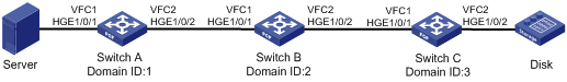
As shown in Figure 1, configure FCoE to meet the following requirements:
· Any two FCF switches can communicate with each other.
· SAN traffic can be transmitted on lossless Ethernet.
· The server can access the disk device through the fabric.
Analysis
To meet the network requirements, you must perform the following tasks:
· To transmit SAN traffic over lossless Ethernet links, you must perform the following tasks:
¡ Configure DCBX, PFC in auto mode, and ETS on the Ethernet interface connecting a switch to a server.
¡ Configure DCBX and PFC in auto mode on the Ethernet interface connecting a switch to a disk device.
¡ Forcibly enable PFC on the Ethernet interfaces interconnecting switches.
· For the server to access the resources in the disk device, configure the members in the default zone to access each other.
· To adapt to the simple and stable network topology, use the static method to build the fabric and configure FC static routes.
Software versions used
This configuration example was created and verified on R6301.
Restrictions and guidelines
Before configuring FC static routes, determine a domain ID for each FCF switch in the fabric.
Procedures
Configuring Switch A
1. Configure the advanced mode:
# Configure the switch to operate in advanced mode. (Skip this step if the switch is already operating in advanced mode.)
<SwitchA> system-view
[SwitchA] system-working-mode advance
Do you want to change the system working mode? [Y/N]:y
The system working mode is changed, please save the configuration and reboot the
system to make it effective.
# Save the configuration.
[SwitchA] save
The current configuration will be written to the device. Are you sure? [Y/N]:y
Please input the file name(*.cfg)[flash:/startup.cfg]
(To leave the existing filename unchanged, press the enter key):
Validating file. Please wait...
Saved the current configuration to mainboard device successfully.
Slot 1:
Save next configuration file successfully.
[SwitchA] quit
# Reboot the switch.
<SwitchA> reboot
Start to check configuration with next startup configuration file, please wait.........DONE!
This command will reboot the device. Continue? [Y/N]:y
Now rebooting, please wait...
2. Configure DCBX:
# Enable LLDP globally.
<SwitchA> system-view
[SwitchA] lldp global enable
# Enable LLDP on interface HundredGigE 1/0/1, and enable the interface to advertise DCBX TLVs.
[SwitchA] interface hundredgige 1/0/1
[SwitchA-HundredGigE1/0/1] lldp enable
[SwitchA-HundredGigE1/0/1] lldp tlv-enable dot1-tlv dcbx
[SwitchA-HundredGigE1/0/1] quit
# Create a Layer 2 ACL named DCBX.
[SwitchA] acl mac name DCBX
# Configure two rules in the ACL to match FCoE frames (protocol type 0x8906) and FIP frames (protocol type 0x8914).
[SwitchA-acl-ethernetframe-DCBX] rule 0 permit type 8906 ffff
[SwitchA-acl-ethernetframe-DCBX] rule 5 permit type 8914 ffff
[SwitchA-acl-ethernetframe-DCBX] quit
# Create a class named DCBX with the operator as OR, and specify ACL DCBX as the match criterion.
[SwitchA] traffic classifier DCBX operator or
[SwitchA-classifier-DCBX] if-match acl mac name DCBX
[SwitchA-classifier-DCBX] quit
# Create a behavior named DCBX, and configure the action of marking packets with 802.1p priority 3.
[SwitchA] traffic behavior DCBX
[SwitchA-behavior-DCBX] remark dot1p 3
[SwitchA-behavior-DCBX] quit
# Create a QoS policy named DCBX.
[SwitchA] qos policy DCBX
# Associate the class DCBX with the behavior DCBX in the QoS policy, and specify that the class-behavior association applies only to DCBX.
[SwitchA-qospolicy-DCBX] classifier DCBX behavior DCBX mode dcbx
[SwitchA-qospolicy-DCBX] quit
# Apply the QoS policy DCBX to the outbound direction of HundredGigE 1/0/1.
[SwitchA] interface hundredgige 1/0/1
[SwitchA-HundredGigE1/0/1] qos apply policy DCBX outbound
3. Configure PFC:
# Configure interface HundredGigE 1/0/1 to automatically negotiate with its peer to enable PFC.
[SwitchA-HundredGigE1/0/1] priority-flow-control auto
# Enable PFC for 802.1p priority 3 on the interface.
[SwitchA-HundredGigE1/0/1] priority-flow-control no-drop dot1p 3
# Configure the interface to trust the 802.1p priority carried in packets.
[SwitchA-HundredGigE1/0/1] qos trust dot1p
[SwitchA-HundredGigE1/0/1] quit
# Forcibly enable PFC on interface HundredGigE 1/0/2.
[SwitchA] interface hundredgige 1/0/2
[SwitchA-HundredGigE1/0/2] priority-flow-control enable
# Enable PFC for 802.1p priority 3 on the interface.
[SwitchA-HundredGigE1/0/2] priority-flow-control no-drop dot1p 3
# Configure the interface to trust the 802.1p priority carried in packets.
[SwitchA-HundredGigE1/0/2] qos trust dot1p
[SwitchA-HundredGigE1/0/2] quit
4. Configure ETS:
# Configure the 802.1p-lp priority map as follows:
¡ Map 802.1p priority 3 to local precedence 1 (corresponding to queue 1).
¡ Map all other 802.1p priorities to local precedence 0 (corresponding to queue 0).
[SwitchA] qos map-table dot1p-lp
[SwitchA-maptbl-dot1p-lp] import 3 export 1
[SwitchA-maptbl-dot1p-lp] import 0 1 2 4 5 6 7 export 0
[SwitchA-maptbl-dot1p-lp] quit
# Enable byte-count WRR on HundredGigE 1/0/1.
[SwitchA] interface hundredgige 1/0/1
[SwitchA-HundredGigE1/0/1] qos wrr byte-count
# Assign 50% of the interface bandwidth to queue 1 (af1) for FCoE traffic.
[SwitchA-HundredGigE1/0/1] qos wrr af1 group 1 byte-count 1
# Assign 50% of the interface bandwidth to queue 0 (be) for standard LAN traffic.
[SwitchA-HundredGigE1/0/1] qos wrr be group 1 byte-count 1
# Assign all other queues on HundredGigE 1/0/1 to the SP group.
[SwitchA-HundredGigE1/0/1] qos wrr af2 group sp
[SwitchA-HundredGigE1/0/1] qos wrr af3 group sp
[SwitchA-HundredGigE1/0/1] qos wrr af4 group sp
[SwitchA-HundredGigE1/0/1] qos wrr ef group sp
[SwitchA-HundredGigE1/0/1] qos wrr cs6 group sp
[SwitchA-HundredGigE1/0/1] qos wrr cs7 group sp
[SwitchA-HundredGigE1/0/1] quit
5. Configure FCoE:
# Configure the switch to operate in FCF mode.
[SwitchA] fcoe-mode fcf
# Disable the fabric configuration function in VSAN 1.
[SwitchA] vsan 1
[SwitchA-vsan1] undo domain configure enable
# Configure a fabric name in VSAN 1.
[SwitchA-vsan1] fabric-name 11:11:11:11:11:11:11:11
# Configure the domain ID as 1 in VSAN 1.
[SwitchA-vsan1] domain-id 1 static
Nondisruptive reconfiguration might be performed or the switch might be isolated. Continue? [Y/N]:y
[SwitchA-vsan1] quit
# Create interface VFC 1, bind VFC 1 to interface HundredGigE 1/0/1, and assign VFC 1 to VSAN 1 as a trunk port.
[SwitchA] interface vfc 1
[SwitchA-Vfc1] bind interface hundredgige 1/0/1
[SwitchA-Vfc1] port trunk vsan 1
[SwitchA-Vfc1] quit
# Create interface VFC 2, and configure it to operate in E mode.
[SwitchA] interface vfc 2
[SwitchA-Vfc2] fc mode e
# Bind interface VFC 2 to interface HundredGigE 1/0/2, and assign VFC 2 to VSAN 1 as a trunk port.
[SwitchA-Vfc2] bind interface hundredgige 1/0/2
[SwitchA-Vfc2] port trunk vsan 1
[SwitchA-Vfc2] quit
# Assign interfaces HundredGigE 1/0/1 and HundredGigE 1/0/2 to VLAN 10 as trunk ports.
[SwitchA] interface range hundredgige 1/0/1 to hundredgige 1/0/2
[SwitchA-if-range] port link-type trunk
[SwitchA-if-range] port trunk permit vlan 10
[SwitchA-if-range] quit
# Enable FCoE for VLAN 10 and map VLAN 10 to VSAN 1.
[SwitchA] vlan 10
[SwitchA-vlan10] fcoe enable vsan 1
[SwitchA-vlan10] quit
# Permit the members in the default zone of VSAN 1 to access each other.
[SwitchA] vsan 1
[SwitchA-vsan1] zone default-zone permit
# Configure static routes to Switch B and Switch C.
[SwitchA-vsan1] fc route-static 020000 8 vfc 2
[SwitchA-vsan1] fc route-static 030000 8 vfc 2
[SwitchA-vsan1] quit
Configuring Switch B
1. Configure the advanced mode:
# Configure the switch to operate in advanced mode. (Skip this step if the switch is already operating in advanced mode.)
<SwitchB> system-view
[SwitchB] system-working-mode advance
Do you want to change the system working mode? [Y/N]:y
The system working mode is changed, please save the configuration and reboot the
system to make it effective.
# Save the configuration.
[SwitchB] save
The current configuration will be written to the device. Are you sure? [Y/N]:y
Please input the file name(*.cfg)[flash:/startup.cfg]
(To leave the existing filename unchanged, press the enter key):
Validating file. Please wait...
Saved the current configuration to mainboard device successfully.
Slot 1:
Save next configuration file successfully.
[SwitchB] quit
# Reboot the switch.
<SwitchB> reboot
Start to check configuration with next startup configuration file, please wait.........DONE!
This command will reboot the device. Continue? [Y/N]:y
Now rebooting, please wait...
2. Configure PFC on interfaces HundredGigE 1/0/1 and HundredGigE 1/0/2:
<SwitchB> system-view
[SwitchB] interface range hundredgige 1/0/1 to hundredgige 1/0/2
# Forcibly enable PFC on the interfaces.
[SwitchB-if-range] priority-flow-control enable
# Enable PFC for 802.1p priority 3 on the interfaces.
[SwitchB-if-range] priority-flow-control no-drop dot1p 3
# Configure the interfaces to trust the 802.1p priority carried in packets.
[SwitchB-if-range] qos trust dot1p
[SwitchB-if-range] quit
3. Configure FCoE:
# Configure the switch to operate in FCF mode.
[SwitchB] fcoe-mode fcf
# Disable the fabric configuration function in VSAN 1.
[SwitchB] vsan 1
[SwitchB-vsan1] undo domain configure enable
# Configure a fabric name in VSAN 1.
[SwitchB-vsan1] fabric-name 11:11:11:11:11:11:11:11
# Configure the domain ID as 2 in VSAN 1.
[SwitchB-vsan1] domain-id 2 static
Nondisruptive reconfiguration might be performed or the switch might be isolated. Continue? [Y/N]:y
[SwitchB-vsan1] quit
# Create interface VFC 1, and configure it to operate in E mode.
[SwitchB] interface vfc 1
[SwitchB-Vfc1] fc mode e
# Bind interface VFC 1 to interface HundredGigE 1/0/1, and assign VFC 1 to VSAN 1 as a trunk port.
[SwitchB-Vfc1] bind interface hundredgige 1/0/1
[SwitchB-Vfc1] port trunk vsan 1
[SwitchB-Vfc1] quit
# Create interface VFC 2, and configure it to operate in E mode.
[SwitchB] interface vfc 2
[SwitchB-Vfc2] fc mode e
# Bind interface VFC 2 to interface HundredGigE 1/0/2, and assign VFC 2 to VSAN 1 as a trunk port.
[SwitchB-Vfc2] bind interface hundredgige 1/0/2
[SwitchB-Vfc2] port trunk vsan 1
[SwitchB-Vfc2] quit
# Assign interfaces HundredGigE 1/0/1 and HundredGigE 1/0/2 to VLAN 10 as trunk ports.
[SwitchB] interface range hundredgige 1/0/1 to hundredgige 1/0/2
[SwitchB-if-range] port link-type trunk
[SwitchB-if-range] port trunk permit vlan 10
[SwitchB-if-range] quit
# Enable FCoE for VLAN 10 and map VLAN 10 to VSAN 1.
[SwitchB] vlan 10
[SwitchB-vlan10] fcoe enable vsan 1
[SwitchB-vlan10] quit
# Permit the members in the default zone of VSAN 1 to access each other.
[SwitchB] vsan 1
[SwitchB-vsan1] zone default-zone permit
# Configure static routes to Switch A and Switch C.
[SwitchB-vsan1] fc route-static 010000 8 vfc 1
[SwitchB-vsan1] fc route-static 030000 8 vfc 2
[SwitchB-vsan1] quit
Configuring Switch C
1. Configure the advanced mode:
# Configure the switch to operate in advanced mode. (Skip this step if the switch is already operating in advanced mode.)
<SwitchC> system-view
[SwitchC] system-working-mode advance
Do you want to change the system working mode? [Y/N]:y
The system working mode is changed, please save the configuration and reboot the
system to make it effective.
# Save the configuration.
[SwitchC] save
The current configuration will be written to the device. Are you sure? [Y/N]:y
Please input the file name(*.cfg)[flash:/startup.cfg]
(To leave the existing filename unchanged, press the enter key):
Validating file. Please wait...
Saved the current configuration to mainboard device successfully.
Slot 1:
Save next configuration file successfully.
[SwitchC] quit
# Reboot the switch.
<SwitchC> reboot
Start to check configuration with next startup configuration file, please wait.........DONE!
This command will reboot the device. Continue? [Y/N]:y
Now rebooting, please wait...
2. Configure DCBX:
# Enable LLDP globally.
<SwitchC> system-view
[SwitchC] lldp global enable
# Enable LLDP on interface HundredGigE 1/0/2, and enable the interface to advertise DCBX TLVs.
[SwitchC] interface hundredgige 1/0/2
[SwitchC-HundredGigE1/0/2] lldp enable
[SwitchC-HundredGigE1/0/2] lldp tlv-enable dot1-tlv dcbx
[SwitchC-HundredGigE1/0/2] quit
# Create a Layer 2 ACL named DCBX.
[SwitchC] acl mac name DCBX
# Configure two rules in the ACL to match FCoE frames (protocol type 0x8906) and FIP frames (protocol type 0x8914).
[SwitchC-acl-ethernetframe-DCBX] rule 0 permit type 8906 ffff
[SwitchC-acl-ethernetframe-DCBX] rule 5 permit type 8914 ffff
[SwitchC-acl-ethernetframe-DCBX] quit
# Create a class named DCBX with the operator as OR, and specify ACL DCBX as the match criterion.
[SwitchC] traffic classifier DCBX operator or
[SwitchC-classifier-DCBX] if-match acl mac name DCBX
[SwitchC-classifier-DCBX] quit
# Create a behavior named DCBX, and configure the action of marking packets with 802.1p priority 3.
[SwitchC] traffic behavior DCBX
[SwitchC-behavior-DCBX] remark dot1p 3
[SwitchC-behavior-DCBX] quit
# Create a QoS policy named DCBX.
[SwitchC] qos policy DCBX
# Associate the class DCBX with the behavior DCBX in the QoS policy, and specify that the class-behavior association applies only to DCBX.
[SwitchC-qospolicy-DCBX] classifier DCBX behavior DCBX mode dcbx
[SwitchC-qospolicy-DCBX] quit
# Apply the QoS policy DCBX to the outbound direction of HundredGigE 1/0/2.
[SwitchC] interface hundredgige 1/0/2
[SwitchC-HundredGigE1/0/2] qos apply policy DCBX outbound
3. Configure PFC:
# Configure interface HundredGigE 1/0/2 to automatically negotiate with its peer to enable PFC.
[SwitchC-HundredGigE1/0/2] priority-flow-control auto
# Enable PFC for 802.1p priority 3 on the interface.
[SwitchC-HundredGigE1/0/2] priority-flow-control no-drop dot1p 3
# Configure the interface to trust the 802.1p priority carried in packets.
[SwitchC-HundredGigE1/0/2] qos trust dot1p
[SwitchC-HundredGigE1/0/2] quit
# Forcibly enable PFC on interface HundredGigE 1/0/1.
[SwitchC] interface hundredgige 1/0/1
[SwitchC-HundredGigE1/0/1] priority-flow-control enable
# Enable PFC for 802.1p priority 3 on the interface.
[SwitchC-HundredGigE1/0/1] priority-flow-control no-drop dot1p 3
# Configure the interface to trust the 802.1p priority carried in packets.
[SwitchC-HundredGigE1/0/1] qos trust dot1p
[SwitchC-HundredGigE1/0/1] quit
4. Configure FCoE:
# Configure the switch to operate in FCF mode.
[SwitchC] fcoe-mode fcf
# Disable the fabric configuration function in VSAN 1.
[SwitchC] vsan 1
[SwitchC-vsan1] undo domain configure enable
# Configure a fabric name in VSAN 1.
[SwitchC-vsan1] fabric-name 11:11:11:11:11:11:11:11
# Configure the domain ID as 3 in VSAN 1.
[SwitchC-vsan1] domain-id 3 static
Nondisruptive reconfiguration might be performed or the switch might be isolated. Continue? [Y/N]:y
[SwitchC-vsan1] quit
# Create interface VFC 1, and configure it to operate in E mode.
[SwitchC] interface vfc 1
[SwitchC-Vfc1] fc mode e
# Bind interface VFC 1 to interface HundredGigE 1/0/1, and assign VFC 1 to VSAN 1 as a trunk port.
[SwitchC-Vfc1] bind interface hundredgige 1/0/1
[SwitchC-Vfc1] port trunk vsan 1
[SwitchC-Vfc1] quit
# Create interface VFC 2, bind VFC 2 to interface HundredGigE 1/0/2, and assign VFC 2 to VSAN 1 as a trunk port.
[SwitchC] interface vfc 2
[SwitchC-Vfc2] bind interface hundredgige 1/0/2
[SwitchC-Vfc2] port trunk vsan 1
[SwitchC-Vfc2] quit
# Assign interfaces HundredGigE 1/0/1 and HundredGigE 1/0/2 to VLAN 10 as trunk ports.
[SwitchC] interface range hundredgige 1/0/1 to hundredgige 1/0/2
[SwitchC-if-range] port link-type trunk
[SwitchC-if-range] port trunk permit vlan 10
[SwitchC-if-range] quit
# Enable FCoE for VLAN 10 and map VLAN 10 to VSAN 1.
[SwitchC] vlan 10
[SwitchC-vlan10] fcoe enable vsan 1
[SwitchC-vlan10] quit
# Permit the members in the default zone of VSAN 1 to access each other.
[SwitchC] vsan 1
[SwitchC-vsan1] zone default-zone permit
# Configure static routes to Switch A and Switch B.
[SwitchC-vsan1] fc route-static 010000 8 vfc 1
[SwitchC-vsan1] fc route-static 020000 8 vfc 1
[SwitchC-vsan1] quit
Verifying the configuration
# Verify that Switch A has static routes to Switch B and Switch C.
[SwitchA] display fc routing-table vsan 1
Routing Table: VSAN 1
Destinations : 6 Routes : 6
Destination/mask Protocol Preference Cost Interface
0x020000/8 STATIC 10 0 Vfc2
0x030000/8 STATIC 10 0 Vfc2
0xfffc01/24 DIRECT 0 0 InLoop0
0xfffffa/24 DIRECT 0 0 InLoop0
0xfffffc/24 DIRECT 0 0 InLoop0
0xfffffd/24 DIRECT 0 0 InLoop0
# Verify that Switch B has static routes to Switch A and Switch C.
[SwitchB] display fc routing-table vsan 1
Routing Table: VSAN 1
Destinations : 6 Routes : 6
Destination/mask Protocol Preference Cost Interface
0x010000/8 STATIC 10 0 Vfc1
0x030000/8 STATIC 10 0 Vfc2
0xfffc02/24 DIRECT 0 0 InLoop0
0xfffffa/24 DIRECT 0 0 InLoop0
0xfffffc/24 DIRECT 0 0 InLoop0
0xfffffd/24 DIRECT 0 0 InLoop0
# Verify that Switch C has static routes to Switch A and Switch B.
[SwitchC] display fc routing-table vsan 1
Routing Table: VSAN 1
Destinations : 6 Routes : 6
Destination/mask Protocol Preference Cost Interface
0x010000/8 STATIC 10 0 Vfc1
0x020000/8 STATIC 10 0 Vfc1
0xfffc03/24 DIRECT 0 0 InLoop0
0xfffffa/24 DIRECT 0 0 InLoop0
0xfffffc/24 DIRECT 0 0 InLoop0
0xfffffd/24 DIRECT 0 0 InLoop0
# Verify that you can successfully ping Switch C from Switch A.
[SwitchA] fcping fcid fffc03 vsan 1
FCPING fcid 0xfffc03: 128 data bytes, press CTRL_C to break
Reply from 0xfffc03: bytes = 128 time = 23 ms
Reply from 0xfffc03: bytes = 128 time = 9 ms
Reply from 0xfffc03: bytes = 128 time = 19 ms
Reply from 0xfffc03: bytes = 128 time = 14 ms
Reply from 0xfffc03: bytes = 128 time = 25 ms
--- 0xfffc03 fcping statistics ---
5 packet(s) transmitted
5 packet(s) received
0.00% packet loss
round-trip min/avg/max = 9/18/25 ms
Configuration files
· Switch A:
#
lldp global enable
#
system-working-mode advance
#
fcoe-mode fcf
#
vsan 1
fabric-name 11:11:11:11:11:11:11:11
domain-id 1 static
undo domain configure enable
fc route-static 020000 8 Vfc2
fc route-static 030000 8 Vfc2
zone default-zone permit
#
vlan 10
fcoe enable vsan 1
#
qos map-table dot1p-lp
import 0 export 0
import 2 export 0
import 3 export 1
import 4 export 0
import 5 export 0
import 6 export 0
import 7 export 0
#
traffic classifier DCBX operator or
if-match acl mac name DCBX
#
traffic behavior DCBX
remark dot1p 3
#
qos policy DCBX
classifier DCBX behavior DCBX mode dcbx
#
interface HundredGigE1/0/1
port link-mode bridge
port link-type trunk
port trunk permit vlan 1 10
priority-flow-control auto
priority-flow-control no-drop dot1p 3
lldp tlv-enable dot1-tlv dcbx
qos wrr byte-count
qos wrr af1 group 1 byte-count 1
qos wrr af2 group sp
qos wrr af3 group sp
qos wrr af4 group sp
qos wrr ef group sp
qos wrr cs6 group sp
qos wrr cs7 group sp
qos apply policy DCBX outbound
#
interface HundredGigE1/0/2
port link-mode bridge
port link-type trunk
port trunk permit vlan 1 10
priority-flow-control enable
priority-flow-control no-drop dot1p 3
#
interface Vfc1
port trunk vsan 1
bind interface HundredGigE1/0/1
#
interface Vfc2
fc mode e
port trunk vsan 1
bind interface HundredGigE1/0/2
#
acl mac name DCBX
rule 0 permit type 8906 ffff
rule 5 permit type 8914 ffff
#
· Switch B:
#
system-working-mode advance
#
fcoe-mode fcf
#
vsan 1
fabric-name 11:11:11:11:11:11:11:11
domain-id 2 static
undo domain configure enable
fc route-static 010000 8 Vfc1
fc route-static 030000 8 Vfc2
zone default-zone permit
#
vlan 10
fcoe enable vsan 1
#
interface HundredGigE1/0/1
port link-mode bridge
port link-type trunk
port trunk permit vlan 1 10
priority-flow-control enable
priority-flow-control no-drop dot1p 3
#
interface HundredGigE1/0/2
port link-mode bridge
port link-type trunk
port trunk permit vlan 1 10
priority-flow-control enable
priority-flow-control no-drop dot1p 3
#
interface Vfc1
fc mode e
port trunk vsan 1
bind interface HundredGigE1/0/1
#
interface Vfc2
fc mode e
port trunk vsan 1
bind interface HundredGigE1/0/2
#
· Switch C:
#
lldp global enable
#
system-working-mode advance
#
fcoe-mode fcf
#
vsan 1
fabric-name 11:11:11:11:11:11:11:11
domain-id 3 static
undo domain configure enable
fc route-static 010000 8 Vfc1
fc route-static 020000 8 Vfc1
zone default-zone permit
#
vlan 10
fcoe enable vsan 1
#
traffic classifier DCBX operator or
if-match acl mac name DCBX
#
traffic behavior DCBX
remark dot1p 3
#
qos policy DCBX
classifier DCBX behavior DCBX mode dcbx
#
interface HundredGigE1/0/1
port link-mode bridge
port link-type trunk
port trunk permit vlan 1 10
priority-flow-control enable
priority-flow-control no-drop dot1p 3
#
interface HundredGigE1/0/2
port link-mode bridge
port link-type trunk
port trunk permit vlan 1 10
priority-flow-control auto
priority-flow-control no-drop dot1p 3
lldp tlv-enable dot1-tlv dcbx
qos apply policy DCBX outbound
#
interface Vfc1
fc mode e
port trunk vsan 1
bind interface HundredGigE1/0/1
#
interface Vfc2
port trunk vsan 1
bind interface HundredGigE1/0/2
#
acl mac name DCBX
rule 0 permit type 8906 ffff
rule 5 permit type 8914 ffff
#
Example: Configuring FSPF
Network configuration
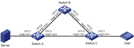
As shown in Figure 2, configure FCoE to meet the following requirements:
· Any FCF switch can forward FC packets to the destination along the shortest path and automatically adapt to network topology changes.
· SAN traffic can be transmitted on lossless Ethernet.
· The server can access the disk device through the fabric.
Analysis
To meet the network requirements, you must perform the following tasks:
· To allow SAN traffic to be transmitted on lossless Ethernet:
¡ Configure DCBX, PFC in auto mode, and ETS on the Ethernet interface connecting a switch to a server.
¡ Configure DCBX and PFC in auto mode on the Ethernet interface connecting a switch to a disk.
¡ Forcibly enable PFC on the Ethernet interfaces interconnecting switches.
· To allow FC packets to be forwarded along the shortest path automatically computed, configure FSPF.
Software versions used
This configuration example was created and verified on R6301.
Restrictions and guidelines
When you configure FCoE, follow these configuration restrictions and guidelines:
· Because the network topology is complex, use the dynamic method to build the fabric.
· Configure the highest switch priority for the FCF switch with better performance, so that FCF switch can be selected as the principal switch.
Procedures
Configuring Switch A
1. Configure the advanced mode:
# Configure the switch to operate in advanced mode. (Skip this step if the switch is already operating in advanced mode.)
<SwitchA> system-view
[SwitchA] system-working-mode advance
Do you want to change the system working mode? [Y/N]:y
The system working mode is changed, please save the configuration and reboot the
system to make it effective.
# Save the configuration.
[SwitchA] save
The current configuration will be written to the device. Are you sure? [Y/N]:y
Please input the file name(*.cfg)[flash:/startup.cfg]
(To leave the existing filename unchanged, press the enter key):
Validating file. Please wait...
Saved the current configuration to mainboard device successfully.
Slot 1:
Save next configuration file successfully.
[SwitchA] quit
# Reboot the switch.
<SwitchA> reboot
Start to check configuration with next startup configuration file, please wait.........DONE!
This command will reboot the device. Continue? [Y/N]:y
Now rebooting, please wait...
2. Configure DCBX:
# Enable LLDP globally.
<SwitchA> system-view
[SwitchA] lldp global enable
# Enable LLDP on interface HundredGigE 1/0/1, and enable the interface to advertise DCBX TLVs.
[SwitchA] interface hundredgige 1/0/1
[SwitchA-HundredGigE1/0/1] lldp enable
[SwitchA-HundredGigE1/0/1] lldp tlv-enable dot1-tlv dcbx
[SwitchA-HundredGigE1/0/1] quit
# Create a Layer 2 ACL named DCBX.
[SwitchA] acl mac name DCBX
# Configure two rules in the ACL to match FCoE frames (protocol type 0x8906) and FIP frames (protocol type 0x8914).
[SwitchA-acl-ethernetframe-DCBX] rule 0 permit type 8906 ffff
[SwitchA-acl-ethernetframe-DCBX] rule 5 permit type 8914 ffff
[SwitchA-acl-ethernetframe-DCBX] quit
# Create a class named DCBX with the operator as OR, and specify ACL DCBX as the match criterion.
[SwitchA] traffic classifier DCBX operator or
[SwitchA-classifier-DCBX] if-match acl mac name DCBX
[SwitchA-classifier-DCBX] quit
# Create a behavior named DCBX, and configure the action of marking packets with 802.1p priority 3.
[SwitchA] traffic behavior DCBX
[SwitchA-behavior-DCBX] remark dot1p 3
[SwitchA-behavior-DCBX] quit
# Create a QoS policy named DCBX.
[SwitchA] qos policy DCBX
# Associate the class DCBX with the behavior DCBX in the QoS policy, and specify that the class-behavior association applies only to DCBX.
[SwitchA-qospolicy-DCBX] classifier DCBX behavior DCBX mode dcbx
[SwitchA-qospolicy-DCBX] quit
# Apply the QoS policy DCBX to the outbound direction of HundredGigE 1/0/1.
[SwitchA] interface hundredgige 1/0/1
[SwitchA-HundredGigE1/0/1] qos apply policy DCBX outbound
3. Configure PFC:
# Configure interface HundredGigE 1/0/1 to automatically negotiate with its peer to enable PFC.
[SwitchA-HundredGigE1/0/1] priority-flow-control auto
# Enable PFC for 802.1p priority 3 on the interface.
[SwitchA-HundredGigE1/0/1] priority-flow-control no-drop dot1p 3
# Configure the interface to trust the 802.1p priority carried in packets.
[SwitchA-HundredGigE1/0/1] qos trust dot1p
[SwitchA-HundredGigE1/0/1] quit
# Forcibly enable PFC on interface HundredGigE 1/0/2.
[SwitchA] interface hundredgige 1/0/2
[SwitchA-HundredGigE1/0/2] priority-flow-control enable
# Enable PFC for 802.1p priority 3 on the interface.
[SwitchA-HundredGigE1/0/2] priority-flow-control no-drop dot1p 3
# Configure the interface to trust the 802.1p priority carried in packets.
[SwitchA-HundredGigE1/0/2] qos trust dot1p
[SwitchA-HundredGigE1/0/2] quit
4. Configure ETS:
# Configure the 802.1p-lp priority map as follows:
¡ Map 802.1p priority 3 to local precedence 1 (corresponding to queue 1).
¡ Map all other 802.1p priorities to local precedence 0 (corresponding to queue 0).
[SwitchA] qos map-table dot1p-lp
[SwitchA-maptbl-dot1p-lp] import 3 export 1
[SwitchA-maptbl-dot1p-lp] import 0 1 2 4 5 6 7 export 0
[SwitchA-maptbl-dot1p-lp] quit
# Enable byte-count WRR on HundredGigE 1/0/1.
[SwitchA] interface hundredgige 1/0/1
[SwitchA-HundredGigE1/0/1] qos wrr byte-count
# Assign 50% of the interface bandwidth to queue 1 (af1) for FCoE traffic.
[SwitchA-HundredGigE1/0/1] qos wrr af1 group 1 byte-count 1
# Assign 50% of the interface bandwidth to queue 0 (be) for standard LAN traffic.
[SwitchA-HundredGigE1/0/1] qos wrr be group 1 byte-count 1
# Assign all other queues on HundredGigE 1/0/1 to the SP group.
[SwitchA-HundredGigE1/0/1] qos wrr af2 group sp
[SwitchA-HundredGigE1/0/1] qos wrr af3 group sp
[SwitchA-HundredGigE1/0/1] qos wrr af4 group sp
[SwitchA-HundredGigE1/0/1] qos wrr ef group sp
[SwitchA-HundredGigE1/0/1] qos wrr cs6 group sp
[SwitchA-HundredGigE1/0/1] qos wrr cs7 group sp
[SwitchA-HundredGigE1/0/1] quit
5. Configure FCoE:
# Configure the switch to operate in FCF mode.
[SwitchA] fcoe-mode fcf
# Enable the fabric configuration function in VSAN 1. By default, the fabric configuration function is enabled.
[SwitchA] vsan 1
[SwitchA-vsan1] domain configure enable
# Configure the switch priority as 1, so that Switch A can be selected as the principal switch.
[SwitchA-vsan1] priority 1
[SwitchA-vsan1] quit
# Create interface VFC 1, bind VFC 1 to interface HundredGigE 1/0/1, and assign VFC 1 to VSAN 1 as a trunk port.
[SwitchA] interface vfc 1
[SwitchA-Vfc1] bind interface hundredgige 1/0/1
[SwitchA-Vfc1] port trunk vsan 1
[SwitchA-Vfc1] quit
# Create interface VFC 2, and configure it to operate in E mode.
[SwitchA] interface vfc 2
[SwitchA-Vfc2] fc mode e
# Bind interface VFC 2 to interface HundredGigE 1/0/2, and assign VFC 2 to VSAN 1 as a trunk port.
[SwitchA-Vfc2] bind interface hundredgige 1/0/2
[SwitchA-Vfc2] port trunk vsan 1
[SwitchA-Vfc2] quit
# Create interface VFC 3, and configure it to operate in E mode.
[SwitchA] interface vfc 3
[SwitchA-Vfc3] fc mode e
# Bind interface VFC 3 to interface HundredGigE 1/0/3, and assign VFC 3 to VSAN 1 as a trunk port.
[SwitchA-Vfc3] bind interface hundredgige 1/0/3
[SwitchA-Vfc3] port trunk vsan 1
[SwitchA-Vfc3] quit
# Assign interfaces HundredGigE 1/0/1 through HundredGigE 1/0/3 to VLAN 10 as trunk ports.
[SwitchA] interface range hundredgige 1/0/1 to hundredgige 1/0/3
[SwitchA-if-range] port link-type trunk
[SwitchA-if-range] port trunk permit vlan 10
[SwitchA-if-range] quit
# Enable FCoE for VLAN 10 and map VLAN 10 to VSAN 1.
[SwitchA] vlan 10
[SwitchA-vlan10] fcoe enable vsan 1
[SwitchA-vlan10] quit
# Permit the members in the default zone of VSAN 1 to access each other.
[SwitchA] vsan 1
[SwitchA-vsan1] zone default-zone permit
# Enable FSPF in VSAN 1. By default, FSPF is enabled.
[SwitchA-vsan1] fspf enable
[SwitchA-vsan1] quit
Configuring Switch B
1. Configure the advanced mode:
# Configure the switch to operate in advanced mode. (Skip this step if the switch is already operating in advanced mode.)
<SwitchB> system-view
[SwitchB] system-working-mode advance
Do you want to change the system working mode? [Y/N]:y
The system working mode is changed, please save the configuration and reboot the
system to make it effective.
# Save the configuration.
[SwitchB] save
The current configuration will be written to the device. Are you sure? [Y/N]:y
Please input the file name(*.cfg)[flash:/startup.cfg]
(To leave the existing filename unchanged, press the enter key):
Validating file. Please wait...
Saved the current configuration to mainboard device successfully.
Slot 1:
Save next configuration file successfully.
[SwitchB] quit
# Reboot the switch.
<SwitchB> reboot
Start to check configuration with next startup configuration file, please wait.........DONE!
This command will reboot the device. Continue? [Y/N]:y
Now rebooting, please wait...
2. Configure PFC on interfaces HundredGigE 1/0/1 and HundredGigE 1/0/2:
<SwitchB> system-view
[SwitchB] interface range hundredgige 1/0/1 to hundredgige 1/0/2
# Forcibly enable PFC on the interfaces.
[SwitchB-if-range] priority-flow-control enable
# Enable PFC for 802.1p priority 3 on the interfaces.
[SwitchB-if-range] priority-flow-control no-drop dot1p 3
# Configure the interfaces to trust the 802.1p priority carried in packets.
[SwitchB-if-range] qos trust dot1p
[SwitchB-if-range] quit
3. Configure FCoE:
# Configure the switch to operate in FCF mode.
[SwitchB] fcoe-mode fcf
# Enable the fabric configuration function in VSAN 1. By default, the fabric configuration function is enabled.
[SwitchB] vsan 1
[SwitchB-vsan1] domain configure enable
# Configure the domain ID as 2 in VSAN 1.
[SwitchB-vsan1] domain-id 2 preferred
Nondisruptive reconfiguration might be performed or the switch might be isolated. Continue? [Y/N]:y
[SwitchB-vsan1] quit
# Create interface VFC 1, and configure it to operate in E mode.
[SwitchB] interface vfc 1
[SwitchB-Vfc1] fc mode e
# Bind interface VFC 1 to interface HundredGigE 1/0/1, and assign VFC 1 to VSAN 1 as a trunk port.
[SwitchB-Vfc1] bind interface hundredgige 1/0/1
[SwitchB-Vfc1] port trunk vsan 1
[SwitchB-Vfc1] quit
# Create interface VFC 2, and configure it to operate in E mode.
[SwitchB] interface vfc 2
[SwitchB-Vfc2] fc mode e
# Bind interface VFC 2 to interface HundredGigE 1/0/2, and assign VFC 2 to VSAN 1 as a trunk port.
[SwitchB-Vfc2] bind interface hundredgige 1/0/2
[SwitchB-Vfc2] port trunk vsan 1
[SwitchB-Vfc2] quit
# Assign interfaces HundredGigE 1/0/1 and HundredGigE 1/0/2 to VLAN 10 as trunk ports.
[SwitchB] interface range hundredgige 1/0/1 to hundredgige 1/0/2
[SwitchB-if-range] port link-type trunk
[SwitchB-if-range] port trunk permit vlan 10
[SwitchB-if-range] quit
# Enable FCoE for VLAN 10 and map VLAN 10 to VSAN 1.
[SwitchB] vlan 10
[SwitchB-vlan10] fcoe enable vsan 1
[SwitchB-vlan10] quit
# Permit the members in the default zone of VSAN 1 to access each other.
[SwitchB] vsan 1
[SwitchB-vsan1] zone default-zone permit
# Enable FSPF in VSAN 1. By default, FSPF is enabled.
[SwitchA-vsan1] fspf enable
[SwitchB-vsan1] quit
Configuring Switch C
1. Configure the advanced mode:
# Configure the switch to operate in advanced mode. (Skip this step if the switch is already operating in advanced mode.)
<SwitchC> system-view
[SwitchC] system-working-mode advance
Do you want to change the system working mode? [Y/N]:y
The system working mode is changed, please save the configuration and reboot the
system to make it effective.
# Save the configuration.
[SwitchC] save
The current configuration will be written to the device. Are you sure? [Y/N]:y
Please input the file name(*.cfg)[flash:/startup.cfg]
(To leave the existing filename unchanged, press the enter key):
Validating file. Please wait...
Saved the current configuration to mainboard device successfully.
Slot 1:
Save next configuration file successfully.
[SwitchC] quit
# Reboot the switch.
<SwitchC> reboot
Start to check configuration with next startup configuration file, please wait.........DONE!
This command will reboot the device. Continue? [Y/N]:y
Now rebooting, please wait...
2. Configure DCBX:
# Enable LLDP globally.
<SwitchC> system-view
[SwitchC] lldp global enable
# Enable LLDP on interface HundredGigE 1/0/1, and enable the interface to advertise DCBX TLVs.
[SwitchC] interface hundredgige 1/0/1
[SwitchC-HundredGigE1/0/1] lldp enable
[SwitchC-HundredGigE1/0/1] lldp tlv-enable dot1-tlv dcbx
[SwitchC-HundredGigE1/0/1] quit
# Create a Layer 2 ACL named DCBX.
[SwitchC] acl mac name DCBX
# Configure two rules in the ACL to match FCoE frames (protocol type 0x8906) and FIP frames (protocol type 0x8914).
[SwitchC-acl-ethernetframe-DCBX] rule 0 permit type 8906 ffff
[SwitchC-acl-ethernetframe-DCBX] rule 5 permit type 8914 ffff
[SwitchC-acl-ethernetframe-DCBX] quit
# Create a class named DCBX with the operator as OR, and specify ACL DCBX as the match criterion.
[SwitchC] traffic classifier DCBX operator or
[SwitchC-classifier-DCBX] if-match acl mac name DCBX
[SwitchC-classifier-DCBX] quit
# Create a behavior named DCBX, and configure the action of marking packets with 802.1p priority 3.
[SwitchC] traffic behavior DCBX
[SwitchC-behavior-DCBX] remark dot1p 3
[SwitchC-behavior-DCBX] quit
# Create a QoS policy named DCBX.
[SwitchC] qos policy DCBX
# Associate the class DCBX with the behavior DCBX in the QoS policy, and specify that the class-behavior association applies only to DCBX.
[SwitchC-qospolicy-DCBX] classifier DCBX behavior DCBX mode dcbx
[SwitchC-qospolicy-DCBX] quit
# Apply the QoS policy DCBX to the outbound direction of HundredGigE 1/0/1.
[SwitchC] interface hundredgige 1/0/1
[SwitchC-HundredGigE1/0/1] qos apply policy DCBX outbound
3. Configure PFC:
# Configure interface HundredGigE 1/0/1 to automatically negotiate with its peer to enable PFC.
[SwitchC-HundredGigE1/0/1] priority-flow-control auto
# Enable PFC for 802.1p priority 3 on the interface.
[SwitchC-HundredGigE1/0/1] priority-flow-control no-drop dot1p 3
# Configure the interface to trust the 802.1p priority carried in packets.
[SwitchC-HundredGigE1/0/1] qos trust dot1p
[SwitchC-HundredGigE1/0/1] quit
# Forcibly enable PFC on interfaces HundredGigE 1/0/2 and HundredGigE 1/0/3.
[SwitchC] interface range hundredgige 1/0/2 to hundredgige 1/0/3
[SwitchC-if-range] priority-flow-control enable
# Enable PFC for 802.1p priority 3 on the interfaces.
[SwitchC-if-range] priority-flow-control no-drop dot1p 3
# Configure the interfaces to trust the 802.1p priority carried in packets.
[SwitchC-if-range] qos trust dot1p
[SwitchC-if-range] quit
4. Configure FCoE:
# Configure the switch to operate in FCF mode.
[SwitchC] fcoe-mode fcf
# Enable the fabric configuration function in VSAN 1. By default, the fabric configuration function is enabled.
[SwitchC] vsan 1
[SwitchC-vsan1] domain configure enable
# Configure the domain ID as 3 in VSAN 1.
[SwitchC-vsan1] domain-id 3 preferred
Nondisruptive reconfiguration might be performed or the switch might be isolated. Continue? [Y/N]:y
[SwitchC-vsan1] quit
# Create interface VFC 1, bind VFC 1 to interface HundredGigE 1/0/1, and assign VFC 1 to VSAN 1 as a trunk port.
[SwitchC] interface vfc 1
[SwitchC-Vfc1] bind interface hundredgige 1/0/1
[SwitchC-Vfc1] port trunk vsan 1
[SwitchC-Vfc1] quit
# Create interface VFC 2, and configure it to operate in E mode.
[SwitchC] interface vfc 2
[SwitchC-Vfc2] fc mode e
# Bind interface VFC 2 to interface HundredGigE 1/0/2, and assign VFC 2 to VSAN 1 as a trunk port.
[SwitchC-Vfc2] bind interface hundredgige 1/0/2
[SwitchC-Vfc2] port trunk vsan 1
[SwitchC-Vfc2] quit
# Create interface VFC 3, and configure it to operate in E mode.
[SwitchC] interface vfc 3
[SwitchC-Vfc3] fc mode e
# Bind interface VFC 3 to interface HundredGigE 1/0/3, and assign VFC 3 to VSAN 1 as a trunk port.
[SwitchC-Vfc3] bind interface hundredgige 1/0/3
[SwitchC-Vfc3] port trunk vsan 1
[SwitchC-Vfc3] quit
# Assign interfaces HundredGigE 1/0/1 through HundredGigE 1/0/3 to VLAN 10 as trunk ports.
[SwitchC] interface range hundredgige 1/0/1 to hundredgige 1/0/3
[SwitchC-if-range] port link-type trunk
[SwitchC-if-range] port trunk permit vlan 10
[SwitchC-if-range] quit
# Enable FCoE for VLAN 10 and map VLAN 10 to VSAN 1.
[SwitchC] vlan 10
[SwitchC-vlan10] fcoe enable vsan 1
[SwitchC-vlan10] quit
# Permit the members in the default zone of VSAN 1 to access each other.
[SwitchC] vsan 1
[SwitchC-vsan1] zone default-zone permit
# Enable FSPF in VSAN 1. By default, FSPF is enabled.
[SwitchC-vsan1] fspf enable
[SwitchC-vsan1] quit
Verifying the configuration
Verify the configuration on Switch A or Switch C, for example, Switch A.
1. Verify the configuration when all links are available:
# Display the FSPF neighbor information for VSAN 1.
[SwitchA] display fspf neighbor
FSPF neighbor information of VSAN 1(01):
Interface NbrDomain IfIndex NbrIfIndex Dead Time State
Vfc2 2 0x68 0x68 00:01:06 Full
Vfc3 3 0x69 0x69 00:01:06 Full
The output shows that Switch A has two neighbors in VSAN 1 (Switch B with domain ID 2 and Switch C with domain ID 3).
# Display the FC routing table of VSAN 1.
[SwitchA] display fc routing-table vsan 1
Routing Table: VSAN 1
Destinations : 6 Routes : 6
Destination/mask Protocol Preference Cost Interface
0x020000/8 FSPF 20 100 Vfc2
0x030000/8 FSPF 20 100 Vfc3
0xfffc01/24 DIRECT 0 0 InLoop0
0xfffffa/24 DIRECT 0 0 InLoop0
0xfffffc/24 DIRECT 0 0 InLoop0
0xfffffd/24 DIRECT 0 0 InLoop0
The output shows that Switch A learned FSPF routes to Switch B and Switch C.
# Verify that you can successfully ping Switch C from Switch A.
[SwitchA] fcping fcid fffc03 vsan 1
FCPING fcid 0xfffc03: 128 data bytes, press CTRL_C to break.
Reply from 0xfffc03: bytes = 128 time = 1.102 ms
Reply from 0xfffc03: bytes = 128 time = 0.276 ms
Reply from 0xfffc03: bytes = 128 time = 0.253 ms
Reply from 0xfffc03: bytes = 128 time = 0.270 ms
Reply from 0xfffc03: bytes = 128 time = 0.247 ms
--- 0xfffc03 fcping statistics ---
5 packet(s) transmitted
5 packet(s) received
0.00% packet loss
round-trip min/avg/max = 0.247/0.430/1.102 ms
# Verify that the path from Switch A to Switch C is Switch A > Switch C, but not Switch A > Switch B > Switch C.
[SwitchA] fctracert fcid fffc03 vsan 1
Route present for: 0xfffc03, press CTRL_C to break.
20:00:00:0b:46:00:02:82(0xfffc01)
20:00:00:05:30:00:18:db(0xfffc03)
20:00:00:05:30:00:18:db(0xfffc03)
20:00:00:0b:46:00:02:82(0xfffc01)
Fctracert completed.
2. Verify the configuration when the link between Switch A and Switch C is disconnected:
# Display the FC routing table of VSAN 1.
[SwitchA] display fc routing-table vsan 1
Routing Table: VSAN 1
Destinations : 6 Routes : 6
Destination/mask Protocol Preference Cost Interface
0x020000/8 FSPF 20 100 Vfc2
0x030000/8 FSPF 20 200 Vfc2
0xfffc01/24 DIRECT 0 0 InLoop0
0xfffffa/24 DIRECT 0 0 InLoop0
0xfffffc/24 DIRECT 0 0 InLoop0
0xfffffd/24 DIRECT 0 0 InLoop0
The output shows that Switch A still has an FSPF route to Switch C.
# Verify that you can successfully ping Switch C from Switch A.
[SwitchA]fcping fcid fffc03 vsan 1
FCPING fcid 0xfffc03: 128 data bytes, press CTRL_C to break.
Reply from 0xfffc03: bytes = 128 time = 2.846 ms
Reply from 0xfffc03: bytes = 128 time = 2.810 ms
Reply from 0xfffc03: bytes = 128 time = 2.799 ms
Reply from 0xfffc03: bytes = 128 time = 2.908 ms
Reply from 0xfffc03: bytes = 128 time = 3.840 ms
--- 0xfffc03 fcping statistics ---
5 packet(s) transmitted
5 packet(s) received
0.00% packet loss
round-trip min/avg/max = 2.799/3.041/3.840 ms
# Verify that Switch B is on the path from Switch A to Switch C.
[SwitchA] fctracert fcid fffc03 vsan 1
Route present for: 0xfffc03, press CTRL_C to break.
20:00:00:0b:46:00:02:82(0xfffc01)
20:00:00:e0:fc:00:c5:18(0xfffc02)
20:00:00:05:30:00:18:db(0xfffc03)
20:00:00:05:30:00:18:db(0xfffc03)
20:00:00:e0:fc:00:c5:18(0xfffc02)
20:00:00:0b:46:00:02:82(0xfffc01)
Fctracert completed.
The output shows that FSPF selected an alternative path (Switch A > Switch B > Switch C) after the link between Switch A and Switch C is disconnected.
Configuration files
· Switch A:
#
lldp global enable
#
system-working-mode advance
#
fcoe-mode fcf
#
vsan 1
priority 1
zone default-zone permit
#
vlan 10
fcoe enable vsan 1
#
qos map-table dot1p-lp
import 0 export 0
import 2 export 0
import 3 export 1
import 4 export 0
import 5 export 0
import 6 export 0
import 7 export 0
#
traffic classifier DCBX operator or
if-match acl mac name DCBX
#
traffic behavior DCBX
remark dot1p 3
#
qos policy DCBX
classifier DCBX behavior DCBX mode dcbx
#
interface HundredGigE1/0/1
port link-mode bridge
port link-type trunk
port trunk permit vlan 1 10
priority-flow-control auto
priority-flow-control no-drop dot1p 3
lldp tlv-enable dot1-tlv dcbx
qos wrr byte-count
qos wrr af1 group 1 byte-count 1
qos wrr af2 group sp
qos wrr af3 group sp
qos wrr af4 group sp
qos wrr ef group sp
qos wrr cs6 group sp
qos wrr cs7 group sp
qos apply policy DCBX outbound
#
interface HundredGigE1/0/2
port link-mode bridge
port link-type trunk
port trunk permit vlan 1 10
priority-flow-control enable
priority-flow-control no-drop dot1p 3
#
interface HundredGigE1/0/3
port link-mode bridge
port link-type trunk
port trunk permit vlan 1 10
priority-flow-control enable
priority-flow-control no-drop dot1p 3
#
interface Vfc1
port trunk vsan 1
bind interface HundredGigE1/0/1
#
interface Vfc2
fc mode e
port trunk vsan 1
bind interface HundredGigE1/0/2
#
interface Vfc3
fc mode e
port trunk vsan 1
bind interface HundredGigE1/0/3
#
acl mac name DCBX
rule 0 permit type 8906 ffff
rule 5 permit type 8914 ffff
#
· Switch B:
#
system-working-mode advance
#
fcoe-mode fcf
#
vsan 1
domain-id 2 preferred
zone default-zone permit
#
vlan 10
fcoe enable vsan 1
#
interface HundredGigE1/0/1
port link-mode bridge
port link-type trunk
port trunk permit vlan 1 10
priority-flow-control enable
priority-flow-control no-drop dot1p 3
#
interface HundredGigE1/0/2
port link-mode bridge
port link-type trunk
port trunk permit vlan 1 10
priority-flow-control enable
priority-flow-control no-drop dot1p 3
#
interface Vfc1
fc mode e
port trunk vsan 1
bind interface HundredGigE1/0/1
#
interface Vfc2
fc mode e
port trunk vsan 1
bind interface HundredGigE1/0/2
#
· Switch C:
#
lldp global enable
#
system-working-mode advance
#
fcoe-mode fcf
#
vsan 1
domain-id 3 preferred
zone default-zone permit
#
vlan 10
fcoe enable vsan 1
#
traffic classifier DCBX operator or
if-match acl mac name DCBX
#
traffic behavior DCBX
remark dot1p 3
#
qos policy DCBX
classifier DCBX behavior DCBX mode dcbx
#
interface HundredGigE1/0/1
port link-mode bridge
port link-type trunk
port trunk permit vlan 1 10
priority-flow-control auto
priority-flow-control no-drop dot1p 3
lldp tlv-enable dot1-tlv dcbx
qos apply policy DCBX outbound
#
interface HundredGigE1/0/2
port link-mode bridge
port link-type trunk
port trunk permit vlan 1 10
priority-flow-control enable
priority-flow-control no-drop dot1p 3
#
interface HundredGigE1/0/3
port link-mode bridge
port link-type trunk
port trunk permit vlan 1 10
priority-flow-control enable
priority-flow-control no-drop dot1p 3
#
interface Vfc1
port trunk vsan 1
bind interface HundredGigE1/0/1
#
interface Vfc2
fc mode e
port trunk vsan 1
bind interface HundredGigE1/0/2
#
interface Vfc3
fc mode e
port trunk vsan 1
bind interface HundredGigE1/0/3
#
acl mac name DCBX
rule 0 permit type 8906 ffff
rule 5 permit type 8914 ffff
#
Example: Configuring FC zones
Network configuration
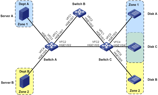
As shown in Figure 3, Disk A is a dedicated disk of Dept A. Disk B is a dedicated disk of Dept B. Disk C is a common disk for Dept A and Dept B. Dept A and Dept B cannot access each other.
Configure FCoE to meet the following requirements:
· SAN traffic can be transmitted on lossless Ethernet.
· Only Server A can access Disk A.
· Only Server B can access Disk B.
· Server A and Server B can access Disk C.
· Server A and Server B cannot access each other.
Analysis
To meet the network requirements, you must perform the following tasks:
· To allow SAN traffic to be transmitted on lossless Ethernet, perform the following tasks:
¡ Configure DCBX and PFC in auto mode on the Ethernet interface connecting a switch to a server.
¡ Configure DCBX, PFC in auto mode, and ETS on the Ethernet interface connecting a switch to a disk.
¡ Forcibly enable PFC on the Ethernet interfaces interconnecting switches.
· To implement access control in VSAN 1, divide VSAN 1 into two zones:
¡ Zone 1 (containing Server A, Disk A, and Disk C).
¡ Zone 2 (containing Server B, Disk B, and Disk C).
· Enable Pairwise for and Zone 1 and Zone 2 because each zone has one server and multiple disks. Configure Server A and Server B as initiators, and configure Disks A, B, and C as targets.
· To ensure data consistency across the fabric, configure FC zones on only one switch, and activate the zone set and distribute it to the entire fabric.
Software versions used
This configuration example was created and verified on R6301.
Procedures
Configuring Switch A
1. Configure the advanced mode:
# Configure the switch to operate in advanced mode. (Skip this step if the switch is already operating in advanced mode.)
<SwitchA> system-view
[SwitchA] system-working-mode advance
Do you want to change the system working mode? [Y/N]:y
The system working mode is changed, please save the configuration and reboot the
system to make it effective.
# Save the configuration.
[SwitchA] save
The current configuration will be written to the device. Are you sure? [Y/N]:y
Please input the file name(*.cfg)[flash:/startup.cfg]
(To leave the existing filename unchanged, press the enter key):
Validating file. Please wait...
Saved the current configuration to mainboard device successfully.
Slot 1:
Save next configuration file successfully.
[SwitchA] quit
# Reboot the switch.
<SwitchA> reboot
Start to check configuration with next startup configuration file, please wait.........DONE!
This command will reboot the device. Continue? [Y/N]:y
Now rebooting, please wait...
2. Configure DCBX:
# Enable LLDP globally.
<SwitchA> system-view
[SwitchA] lldp global enable
# Enable LLDP on interfaces HundredGigE 1/0/3 and HundredGigE 1/0/4, and enable the interfaces to advertise DCBX TLVs.
[SwitchA] interface range hundredgige 1/0/3 to hundredgige 1/0/4
[SwitchA-if-range] lldp enable
[SwitchA-if-range] lldp tlv-enable dot1-tlv dcbx
[SwitchA-if-range] quit
# Create a Layer 2 ACL named DCBX.
[SwitchA] acl mac name DCBX
# Configure two rules in the ACL to match FCoE frames (protocol type 0x8906) and FIP frames (protocol type 0x8914).
[SwitchA-acl-ethernetframe-DCBX] rule 0 permit type 8906 ffff
[SwitchA-acl-ethernetframe-DCBX] rule 5 permit type 8914 ffff
[SwitchA-acl-ethernetframe-DCBX] quit
# Create a class named DCBX with the operator as OR, and specify ACL DCBX as the match criterion.
[SwitchA] traffic classifier DCBX operator or
[SwitchA-classifier-DCBX] if-match acl mac name DCBX
[SwitchA-classifier-DCBX] quit
# Create a behavior named DCBX, and configure the action of marking packets with 802.1p priority 3.
[SwitchA] traffic behavior DCBX
[SwitchA-behavior-DCBX] remark dot1p 3
[SwitchA-behavior-DCBX] quit
# Create a QoS policy named DCBX.
[SwitchA] qos policy DCBX
# Associate the class DCBX with the behavior DCBX in the QoS policy, and specify that the class-behavior association applies only to DCBX.
[SwitchA-qospolicy-DCBX] classifier DCBX behavior DCBX mode dcbx
[SwitchA-qospolicy-DCBX] quit
# Apply the QoS policy DCBX to the outbound direction of HundredGigE 1/0/3 and HundredGigE 1/0/4.
[SwitchA] interface range hundredgige 1/0/3 to hundredgige 1/0/4
[SwitchA-if-range] qos apply policy DCBX outbound
3. Configure PFC:
# Forcibly enable PFC on interfaces HundredGigE 1/0/3 and HundredGigE 1/0/4.
[SwitchA-if-range] priority-flow-control auto
# Enable PFC for 802.1p priority 3 on the interfaces.
[SwitchA-if-range] priority-flow-control no-drop dot1p 3
# Configure the interfaces to trust the 802.1p priority carried in packets.
[SwitchA-if-range] qos trust dot1p
# Forcibly enable PFC on interfaces HundredGigE 1/0/1 and HundredGigE 1/0/2.
[SwitchA] interface range hundredgige 1/0/1 to hundredgige 1/0/2
[SwitchA-if-range] priority-flow-control enable
# Enable PFC for 802.1p priority 3 on the interfaces.
[SwitchA-if-range] priority-flow-control no-drop dot1p 3
# Configure the interfaces to trust the 802.1p priority carried in packets.
[SwitchA-if-range] qos trust dot1p
[SwitchA-if-range] quit
4. Configure ETS:
# Configure the 802.1p-lp priority map as follows:
a. Map 802.1p priority 3 to local precedence 1 (corresponding to queue 1).
b. Map all other 802.1p priorities to local precedence 0 (corresponding to queue 0).
[SwitchA] qos map-table dot1p-lp
[SwitchA-maptbl-dot1p-lp] import 3 export 1
[SwitchA-maptbl-dot1p-lp] import 0 1 2 4 5 6 7 export 0
[SwitchA-maptbl-dot1p-lp] quit
# Enable byte-count WRR on interfaces HundredGigE 1/0/3 and HundredGigE 1/0/4.
[SwitchA] interface range hundredgige 1/0/3 to hundredgige 1/0/4
[SwitchA-if-range] qos wrr byte-count
# Assign 50% of the interface bandwidth to queue 1 (af1) for FCoE traffic.
[SwitchA-if-range] qos wrr af1 group 1 byte-count 1
# Assign 50% of the interface bandwidth to queue 0 (be) for standard LAN traffic.
[SwitchA-if-range] qos wrr be group 1 byte-count 1
# Assign all other queues on HundredGigE 1/0/3 and HundredGigE 1/0/4 to the SP group.
[SwitchA-if-range] qos wrr af2 group sp
[SwitchA-if-range] qos wrr af3 group sp
[SwitchA-if-range] qos wrr af4 group sp
[SwitchA-if-range] qos wrr ef group sp
[SwitchA-if-range] qos wrr cs6 group sp
[SwitchA-if-range] qos wrr cs7 group sp
[SwitchA-if-range] quit
5. Configure FCoE:
# Configure the switch to operate in FCF mode.
[SwitchA] fcoe-mode fcf
# Create VSAN 1.
[SwitchA] vsan 1
# Configure the switch priority as 1, so that Switch A can be selected as the principal switch.
[SwitchA-vsan1] priority 1
[SwitchA-vsan1] quit
# Create interface VFC 1, and configure it to operate in E mode.
[SwitchA] interface vfc 1
[SwitchA-Vfc1] fc mode e
# Bind interface VFC 1 to interface HundredGigE 1/0/1, and assign VFC 1 to VSAN 1 as a trunk port.
[SwitchA-Vfc1] bind interface hundredgige 1/0/1
[SwitchA-Vfc1] port trunk vsan 1
[SwitchA-Vfc1] quit
# Create interface VFC 2, and configure it to operate in E mode.
[SwitchA] interface vfc 2
[SwitchA-Vfc2] fc mode e
# Bind interface VFC 2 to interface HundredGigE 1/0/2, and assign VFC 2 to VSAN 1 as a trunk port.
[SwitchA-Vfc2] bind interface hundredgige 1/0/2
[SwitchA-Vfc2] port trunk vsan 1
[SwitchA-Vfc2] quit
# Create interface VFC 3, bind VFC 3 to interface HundredGigE 1/0/3, and assign VFC 3 to VSAN 1 as a trunk port.
[SwitchA] interface vfc 3
[SwitchA-Vfc3] bind interface hundredgige 1/0/3
[SwitchA-Vfc3] port trunk vsan 1
[SwitchA-Vfc3] quit
# Create interface VFC 4, bind VFC 4 to interface HundredGigE 1/0/4, and assign VFC 4 to VSAN 1 as a trunk port.
[SwitchA] interface vfc 4
[SwitchA-Vfc4] bind interface hundredgige 1/0/4
[SwitchA-Vfc4] port trunk vsan 1
[SwitchA-Vfc4] quit
# Assign interfaces HundredGigE 1/0/1 through HundredGigE 1/0/4 to VLAN 10 as trunk ports.
[SwitchA] interface range hundredgige 1/0/1 to hundredgige 1/0/4
[SwitchA-if-range] port link-type trunk
[SwitchA-if-range] port trunk permit vlan 10
[SwitchA-if-range] quit
# Enable FCoE for VLAN 10 and map VLAN 10 to VSAN 1.
[SwitchA] vlan 10
[SwitchA-vlan10] fcoe enable vsan 1
[SwitchA-vlan10] quit
Configuring Switch B
1. Configure the advanced mode:
# Configure the switch to operate in advanced mode. (Skip this step if the switch is already operating in advanced mode.)
<SwitchB> system-view
[SwitchB] system-working-mode advance
Do you want to change the system working mode? [Y/N]:y
The system working mode is changed, please save the configuration and reboot the
system to make it effective.
# Save the configuration.
[SwitchB] save
The current configuration will be written to the device. Are you sure? [Y/N]:y
Please input the file name(*.cfg)[flash:/startup.cfg]
(To leave the existing filename unchanged, press the enter key):
Validating file. Please wait...
Saved the current configuration to mainboard device successfully.
Slot 1:
Save next configuration file successfully.
[SwitchB] quit
# Reboot the switch.
<SwitchB> reboot
Start to check configuration with next startup configuration file, please wait.........DONE!
This command will reboot the device. Continue? [Y/N]:y
Now rebooting, please wait...
2. Configure PFC on interfaces HundredGigE 1/0/1 and HundredGigE 1/0/2:
<SwitchB> system-view
[SwitchB] interface range hundredgige 1/0/1 to hundredgige 1/0/2
# Forcibly enable PFC on the interfaces.
[SwitchB-if-range] priority-flow-control enable
# Enable PFC for 802.1p priority 3 on the interfaces.
[SwitchB-if-range] priority-flow-control no-drop dot1p 3
# Configure the interfaces to trust the 802.1p priority carried in packets.
[SwitchB-if-range] qos trust dot1p
[SwitchB-if-range] quit
3. Configure FCoE:
# Configure the switch to operate in FCF mode.
[SwitchB] fcoe-mode fcf
# Enable the fabric configuration function in VSAN 1. By default, the fabric configuration function is enabled.
[SwitchB] vsan 1
[SwitchB-vsan1] domain configure enable
# Configure the domain ID as 2 in VSAN 1.
[SwitchB-vsan1] domain-id 2 preferred
Nondisruptive reconfiguration might be performed or the switch might be isolated. Continue? [Y/N]:y
[SwitchB-vsan1] quit
# Create interface VFC 1, and configure it to operate in E mode.
[SwitchB] interface vfc 1
[SwitchB-Vfc1] fc mode e
# Bind interface VFC 1 to interface HundredGigE 1/0/1, and assign VFC 1 to VSAN 1 as a trunk port.
[SwitchB-Vfc1] bind interface hundredgige 1/0/1
[SwitchB-Vfc1] port trunk vsan 1
[SwitchB-Vfc1] quit
# Create interface VFC 2, and configure it to operate in E mode.
[SwitchB] interface vfc 2
[SwitchB-Vfc2] fc mode e
# Bind interface VFC 2 to interface HundredGigE 1/0/2, and assign VFC 2 to VSAN 1 as a trunk port.
[SwitchB-Vfc2] bind interface hundredgige 1/0/2
[SwitchB-Vfc2] port trunk vsan 1
[SwitchB-Vfc2] quit
# Assign interfaces HundredGigE 1/0/1 and HundredGigE 1/0/2 to VLAN 10 as trunk ports.
[SwitchB] interface range hundredgige 1/0/1 to hundredgige 1/0/2
[SwitchB-if-range] port link-type trunk
[SwitchB-if-range] port trunk permit vlan 10
[SwitchB-if-range] quit
# Enable FCoE for VLAN 10 and map VLAN 10 to VSAN 1.
[SwitchB] vlan 10
[SwitchB-vlan10] fcoe enable vsan 1
[SwitchB-vlan10] quit
Configuring Switch C
1. Configure the advanced mode:
# Configure the switch to operate in advanced mode. (Skip this step if the switch is already operating in advanced mode.)
<SwitchC> system-view
[SwitchC] system-working-mode advance
Do you want to change the system working mode? [Y/N]:y
The system working mode is changed, please save the configuration and reboot the
system to make it effective.
# Save the configuration.
[SwitchC] save
The current configuration will be written to the device. Are you sure? [Y/N]:y
Please input the file name(*.cfg)[flash:/startup.cfg]
(To leave the existing filename unchanged, press the enter key):
Validating file. Please wait...
Saved the current configuration to mainboard device successfully.
Slot 1:
Save next configuration file successfully.
[SwitchC] quit
# Reboot the switch.
<SwitchC> reboot
Start to check configuration with next startup configuration file, please wait.........DONE!
This command will reboot the device. Continue? [Y/N]:y
Now rebooting, please wait...
2. Configure DCBX:
# Enable LLDP globally.
<SwitchC> system-view
[SwitchC] lldp global enable
# Enable LLDP on interfaces HundredGigE 1/0/3 through HundredGigE 1/0/5, and enable the interfaces to advertise DCBX TLVs.
[SwitchC] interface range hundredgige 1/0/3 to hundredgige 1/0/5
[SwitchC-if-range] lldp enable
[SwitchC-if-range] lldp tlv-enable dot1-tlv dcbx
[SwitchC-if-range] quit
# Create a Layer 2 ACL named DCBX.
[SwitchC] acl mac name DCBX
# Configure two rules in the ACL to match FCoE frames (protocol type 0x8906) and FIP frames (protocol type 0x8914).
[SwitchC-acl-ethernetframe-DCBX] rule 0 permit type 8906 ffff
[SwitchC-acl-ethernetframe-DCBX] rule 5 permit type 8914 ffff
[SwitchC-acl-ethernetframe-DCBX] quit
# Create a class named DCBX with the operator as OR, and specify ACL DCBX as the match criterion.
[SwitchC] traffic classifier DCBX operator or
[SwitchC-classifier-DCBX] if-match acl mac name DCBX
[SwitchC-classifier-DCBX] quit
# Create a behavior named DCBX, and configure the action of marking packets with 802.1p priority 3.
[SwitchC] traffic behavior DCBX
[SwitchC-behavior-DCBX] remark dot1p 3
[SwitchC-behavior-DCBX] quit
# Create a QoS policy named DCBX.
[SwitchC] qos policy DCBX
# Associate the class DCBX with the behavior DCBX in the QoS policy, and specify that the class-behavior association applies only to DCBX.
[SwitchC-qospolicy-DCBX] classifier DCBX behavior DCBX mode dcbx
[SwitchC-qospolicy-DCBX] quit
# Apply the QoS policy DCBX to the outbound direction of interfaces HundredGigE 1/0/3 through HundredGigE 1/0/5.
[SwitchC] interface range hundredgige 1/0/3 to hundredgige 1/0/5
[SwitchC-if-range] qos apply policy DCBX outbound
3. Configure PFC:
# Forcibly enable PFC on the interfaces HundredGigE 1/0/3 through HundredGigE 1/0/5.
[SwitchC-if-range] priority-flow-control auto
# Enable PFC for 802.1p priority 3 on the interfaces.
[SwitchC-if-range] priority-flow-control no-drop dot1p 3
# Configure the interfaces to trust the 802.1p priority carried in packets.
[SwitchC-if-range] qos trust dot1p
[SwitchC-if-range] quit
# Forcibly enable PFC on the interfaces HundredGigE 1/0/1 and HundredGigE 1/0/2.
[SwitchC] interface range hundredgige 1/0/1 to hundredgige 1/0/2
[SwitchC-if-range] priority-flow-control enable
# Enable PFC for 802.1p priority 3 on the interfaces.
[SwitchC-if-range] priority-flow-control no-drop dot1p 3
# Configure the interfaces to trust the 802.1p priority carried in packets.
[SwitchC-if-range] qos trust dot1p
[SwitchC-if-range] quit
4. Configure FCoE:
# Configure the switch to operate in FCF mode.
[SwitchC] fcoe-mode fcf
# Create VSAN 1.
[SwitchC] vsan 1
# Configure the domain ID as 3 in VSAN 1.
[SwitchC-vsan1] domain-id 3 preferred
Nondisruptive reconfiguration might be performed or the switch might be isolated. Continue? [Y/N]:y
[SwitchC-vsan1] quit
# Create interface VFC 1, and configure it to operate in E mode.
[SwitchC] interface vfc 1
[SwitchC-Vfc1] fc mode e
# Bind interface VFC 1 to interface HundredGigE 1/0/1, and assign VFC 1 to VSAN 1 as a trunk port.
[SwitchC-Vfc1] bind interface hundredgige 1/0/1
[SwitchC-Vfc1] port trunk vsan 1
[SwitchC-Vfc1] quit
# Create interface VFC 2, and configure it to operate in E mode.
[SwitchC] interface vfc 2
[SwitchC-Vfc2] fc mode e
# Bind interface VFC 2 to interface HundredGigE 1/0/2, and assign VFC 2 to VSAN 1 as a trunk port.
[SwitchC-Vfc2] bind interface hundredgige 1/0/2
[SwitchC-Vfc2] port trunk vsan 1
[SwitchC-Vfc2] quit
# Create interface VFC 3, bind it to interface HundredGigE 1/0/3, and assign VFC 3 to VSAN 1 as a trunk port.
[SwitchC] interface vfc 3
[SwitchC-Vfc3] bind interface hundredgige 1/0/3
[SwitchC-Vfc3] port trunk vsan 1
[SwitchC-Vfc3] quit
# Create interface VFC 4, bind it to interface HundredGigE 1/0/4, and assign VFC 4 to VSAN 1 as a trunk port.
[SwitchC] interface vfc 4
[SwitchC-Vfc4] bind interface hundredgige 1/0/4
[SwitchC-Vfc4] port trunk vsan 1
[SwitchC-Vfc4] quit
# Create interface VFC 5, bind it to interface HundredGigE 1/0/5, and assign VFC 5 to VSAN 1 as a trunk port.
[SwitchC] interface vfc 5
[SwitchC-Vfc5] bind interface hundredgige 1/0/5
[SwitchC-Vfc5] port trunk vsan 1
[SwitchC-Vfc5] quit
# Assign interfaces HundredGigE 1/0/1 through HundredGigE 1/0/5 to VLAN 10 as trunk ports.
[SwitchC] interface range hundredgige 1/0/1 to hundredgige 1/0/5
[SwitchC-if-range] port link-type trunk
[SwitchC-if-range] port trunk permit vlan 10
[SwitchC-if-range] quit
# Enable FCoE for VLAN 10 and map VLAN 10 to VSAN 1.
[SwitchC] vlan 10
[SwitchC-vlan10] fcoe enable vsan 1
[SwitchC-vlan10] quit
Displaying FC SAN establishment
On Switch A
# Display domain information in VSAN 1.
[SwitchA] display fc domain vsan 1
Domain Information of VSAN 1:
Running time information:
State: Stable
Switch WWN: 10:00:00:e0:fc:00:c5:18
Fabric name: 10:00:00:e0:fc:00:c5:18
Priority: 1
Domain ID: 1
Configuration information:
Domain configure: Enabled
Domain auto-reconfigure: Disabled
Fabric name: 10:00:00:e0:fc:00:c5:18
Priority: 1
Domain ID: 1 (preferred)
Principal switch running time information:
Priority: 1
Path Interface
Downstream Vfc1
Downstream Vfc2
The output shows that Switch A was selected as the principal switch and assigned itself domain ID 1.
# Display node login information in VSAN 1.
[SwitchA] display fc login vsan 1
Interface VSAN FCID Node WWN Port WWN
Vfc3 1 0x010000 21:01:00:1a:32:a0:fa:12 21:01:00:1a:32:a0:fa:11
Vfc4 1 0x010001 21:01:00:1b:32:b0:fb:12 21:01:00:1b:32:b0:fb:11
The output shows that Switch A assigned FC IDs 0x010000 and 0x010001 to Server A and Server B, respectively.
# Display brief information about the name service database in VSAN 1.
[SwitchA] display fc name-service database vsan 1
VSAN 1:
FCID Type PWWN(vendor) FC4-type:feature
0x010000 0x01(N) 21:01:00:1a:32:a0:fa:11 SCSI-FCP:Initiator
0x010001 0x01(N) 21:01:00:1b:32:b0:fb:11 SCSI-FCP:Initiator
0x030000 0x01(N) 10:00:00:05:30:00:25:a1 SCSI-FCP:Target
0x030001 0x01(N) 10:00:00:05:30:00:25:c1 SCSI-FCP:Target
0x030002 0x01(N) 10:00:00:05:30:00:25:b1 SCSI-FCP:Target
The output shows that all nodes completed name service registrations.
On Switch C
# Display domain information in VSAN 1.
[SwitchC] display fc domain vsan 1
Domain Information of VSAN 1:
Running time information:
State: Stable
Switch WWN: 10:00:74:25:8a:02:4c:00
Fabric name: 10:00:00:e0:fc:00:c5:18
Priority: 128
Domain ID: 3
Configuration information:
Domain configure: Enabled
Domain auto-reconfigure: Disabled
Fabric name: 10:00:00:e0:fc:00:c5:18
Priority: 128
Domain ID: 3 (preferred)
Principal switch running time information:
Priority: 1
Path Interface
Upstream Vfc2
The output shows that the principal switch assigned domain ID 3 to Switch C.
# Display node login information in VSAN 1.
[SwitchC] display fc login vsan 1
Interface VSAN FCID Node WWN Port WWN
Vfc3 1 0x030000 10:00:00:05:30:00:25:a1 10:00:00:05:30:00:25:a2
Vfc4 1 0x030001 10:00:00:05:30:00:25:c1 10:00:00:05:30:00:25:c2
Vfc5 1 0x030002 10:00:00:05:30:00:25:b1 10:00:00:05:30:00:25:b2
The output shows that Switch C assigned FC IDs 0x030000, 0x030001, and 0x030002 to Disk A, Disk C, and Disk B, respectively.
# Display brief information about the name service database in VSAN 1.
[SwitchC] display fc name-service database vsan 1
VSAN 1:
FCID Type PWWN(vendor) FC4-type:feature
0x010000 0x01(N) 21:01:00:1a:32:a0:fa:11 SCSI-FCP:Initiator
0x010001 0x01(N) 21:01:00:1b:32:b0:fb:11 SCSI-FCP:Initiator
0x030000 0x01(N) 10:00:00:05:30:00:25:a1 SCSI-FCP:Target
0x030001 0x01(N) 10:00:00:05:30:00:25:c1 SCSI-FCP:Target
0x030002 0x01(N) 10:00:00:05:30:00:25:b1 SCSI-FCP:Target
The output shows that all nodes completed name service registrations.
Configuring FC zones
# Enable the enhanced zoning mode in VSAN 1.
[SwitchA-vsan1] zone mode enhanced
The zoning database in this switch would be distributed throughout the fabric. Continue? [Y/N]:y
# Create a zone named Zone1, and enable the Pairwise feature for Zone1.
[SwitchA-vsan1] zone name Zone1
[SwitchA-vsan1-zone-Zone1] pairwise-zoning enable
# Specify FC ID 010000 as its initiator member, and specify FC IDs 030000 and 030001 as its target members.
[SwitchA-vsan1-zone-Zone1] member fcid 010000 initiator
[SwitchA-vsan1-zone-Zone1] member fcid 030000 target
[SwitchA-vsan1-zone-Zone1] member fcid 030001 target
[SwitchA-vsan1-zone-Zone1] quit
# Create a zone named Zone2, and enable the Pairwise feature for Zone2.
[SwitchA-vsan1] zone name Zone2
[SwitchA-vsan1-zone-Zone2] pairwise-zoning enable
# Specify FC ID 010001 as its initiator member, and specify FC IDs 030001 and 030002 as its target members.
[SwitchA-vsan1-zone-Zone2] member fcid 010001 initiator
[SwitchA-vsan1-zone-Zone2] member fcid 030001 target
[SwitchA-vsan1-zone-Zone2] member fcid 030002 target
[SwitchA-vsan1-zone-Zone2] quit
# Create a zone set named Zoneset1, and add zones Zone1 and Zone2 as its members.
[SwitchA-vsan1] zoneset name Zoneset1
[SwitchA-vsan1-zoneset-Zoneset1] member Zone1
[SwitchA-vsan1-zoneset-Zoneset1] member Zone2
[SwitchA-vsan1-zoneset-Zoneset1] quit
# Activate Zoneset1 as the active zone set, and distribute it to the entire fabric.
[SwitchA-vsan1] zoneset activate name Zoneset1
[SwitchA-vsan1] quit
Verifying the configuration
Verify the configuration on any switch, for example, Switch C.
# Display zone set information for VSAN 1.
<SwitchC> display zoneset vsan 1
VSAN 1:
zoneset name Zoneset1
fcid 0x010000 initiator
fcid 0x030000 target
fcid 0x030001 target
zone name Zone2
fcid 0x010001 initiator
fcid 0x030001 target
fcid 0x030002 target
The output shows that VSAN 1 was divided into two zones: Zone 1 and Zone 2.
# Display the zones to which FC ID 030001 belongs.
<SwitchC> display zone member fcid 030001
fcid 0x030001
VSAN 1:
zone Zone1
zone Zone2
The output shows that Disk C belongs to both Zone 1 and Zone 2 (both Server 1 and Server 2 can access Disk C).
# Display information about the active zone set in VSAN 1.
<SwitchC> display zoneset active vsan 1
VSAN 1:
zoneset name Zoneset1
zone name Zone1
*fcid 0x010000
*fcid 0x030000
*fcid 0x030001
zone name Zone2
*fcid 0x010001
*fcid 0x030001
*fcid 0x030002
The output shows that Zone set 1 is the active zone set of VSAN 1.
Configuration files
· Switch A:
#
lldp global enable
#
system-working-mode advance
#
fcoe-mode fcf
#
vsan 1
priority 1
zone mode enhanced
zone name Zone1
pairwise-zoning enable
member fcid 010000 initiator
member fcid 030000 target
member fcid 030001 target
zone name Zone2
member fcid 010001 initiator
member fcid 030001 target
member fcid 030002 target
zoneset name Zoneset1
member Zone1
member Zone2
zoneset activate name Zoneset1
#
vlan 10
fcoe enable vsan 1
#
qos map-table dot1p-lp
import 0 export 0
import 2 export 0
import 3 export 1
import 4 export 0
import 5 export 0
import 6 export 0
import 7 export 0
#
traffic classifier DCBX operator or
if-match acl mac name DCBX
#
traffic behavior DCBX
remark dot1p 3
#
qos policy DCBX
classifier DCBX behavior DCBX mode dcbx
#
interface HundredGigE1/0/1
port link-mode bridge
port link-type trunk
port trunk permit vlan 1 10
priority-flow-control enable
priority-flow-control no-drop dot1p 3
#
interface HundredGigE1/0/2
port link-mode bridge
port link-type trunk
port trunk permit vlan 1 10
priority-flow-control enable
priority-flow-control no-drop dot1p 3
#
interface HundredGigE1/0/3
port link-mode bridge
port link-type trunk
port trunk permit vlan 1 10
priority-flow-control auto
priority-flow-control no-drop dot1p 3
lldp tlv-enable dot1-tlv dcbx
qos wrr byte-count
qos wrr af1 group 1 byte-count 1
qos wrr af2 group sp
qos wrr af3 group sp
qos wrr af4 group sp
qos wrr ef group sp
qos wrr cs6 group sp
qos wrr cs7 group sp
qos apply policy DCBX outbound
#
interface HundredGigE1/0/4
port link-mode bridge
port link-type trunk
port trunk permit vlan 1 10
priority-flow-control auto
priority-flow-control no-drop dot1p 3
lldp tlv-enable dot1-tlv dcbx
qos wrr byte-count
qos wrr af1 group 1 byte-count 1
qos wrr af2 group sp
qos wrr af3 group sp
qos wrr af4 group sp
qos wrr ef group sp
qos wrr cs6 group sp
qos wrr cs7 group sp
qos apply policy DCBX outbound
#
interface Vfc1
fc mode e
port trunk vsan 1
bind interface HundredGigE1/0/1
#
interface Vfc2
fc mode e
port trunk vsan 1
bind interface HundredGigE1/0/2
#
interface Vfc3
port trunk vsan 1
bind interface HundredGigE1/0/3
#
interface Vfc4
port trunk vsan 1
bind interface HundredGigE1/0/4
#
acl mac name DCBX
rule 0 permit type 8906 ffff
rule 5 permit type 8914 ffff
#
· Switch B:
#
system-working-mode advance
#
fcoe-mode fcf
#
vsan 1
domain-id 2 preferred
#
vlan 10
fcoe enable vsan 1
#
interface HundredGigE1/0/1
port link-mode bridge
port link-type trunk
port trunk permit vlan 1 10
priority-flow-control enable
priority-flow-control no-drop dot1p 3
#
interface HundredGigE1/0/2
port link-mode bridge
port link-type trunk
port trunk permit vlan 1 10
priority-flow-control enable
priority-flow-control no-drop dot1p 3
#
interface Vfc1
fc mode e
port trunk vsan 1
bind interface HundredGigE1/0/1
#
interface Vfc2
fc mode e
port trunk vsan 1
bind interface HundredGigE1/0/2
#
· Switch C:
#
lldp global enable
#
system-working-mode advance
#
fcoe-mode fcf
#
vsan 1
domain-id 3 preferred
#
vlan 10
fcoe enable vsan 1
#
traffic classifier DCBX operator or
if-match acl mac name DCBX
#
traffic behavior DCBX
remark dot1p 3
#
qos policy DCBX
classifier DCBX behavior DCBX mode dcbx
#
interface HundredGigE1/0/1
port link-mode bridge
port link-type trunk
port trunk permit vlan 1 10
priority-flow-control enable
priority-flow-control no-drop dot1p 3
#
interface HundredGigE1/0/2
port link-mode bridge
port link-type trunk
port trunk permit vlan 1 10
priority-flow-control enable
priority-flow-control no-drop dot1p 3
#
interface HundredGigE1/0/3
port link-mode bridge
port link-type trunk
port trunk permit vlan 1 10
priority-flow-control auto
priority-flow-control no-drop dot1p 3
lldp tlv-enable dot1-tlv dcbx
qos apply policy DCBX outbound
#
interface HundredGigE1/0/4
port link-mode bridge
port link-type trunk
port trunk permit vlan 1 10
priority-flow-control auto
priority-flow-control no-drop dot1p 3
lldp tlv-enable dot1-tlv dcbx
qos apply policy DCBX outbound
#
interface HundredGigE1/0/5
port link-mode bridge
port link-type trunk
port trunk permit vlan 1 10
priority-flow-control auto
priority-flow-control no-drop dot1p 3
lldp tlv-enable dot1-tlv dcbx
qos apply policy DCBX outbound
#
interface Vfc1
fc mode e
port trunk vsan 1
bind interface HundredGigE1/0/1
#
interface Vfc2
fc mode e
port trunk vsan 1
bind interface HundredGigE1/0/2
#
interface Vfc3
port trunk vsan 1
bind interface HundredGigE1/0/3
#
interface Vfc4
port trunk vsan 1
bind interface HundredGigE1/0/4
#
interface Vfc5
port trunk vsan 1
bind interface HundredGigE1/0/5
#
acl mac name DCBX
rule 0 permit type 8906 ffff
rule 5 permit type 8914 ffff
#
Example: Configuring FIP snooping
Network configuration
As shown in Figure 4, configure FCoE to meet the following requirements:
· SAN traffic can be transmitted on lossless Ethernet.
· Only successfully registered servers can access the fabric.
· Server A and Server B cannot access each other.
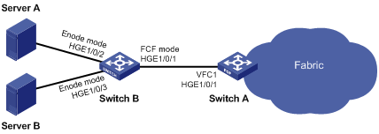
Analysis
To meet the network requirements, you must perform the following tasks:
· To allow SAN traffic to be transmitted on lossless Ethernet, perform the following tasks:
¡ Configure DCBX, PFC in auto mode, and ETS on the Ethernet interface connecting a switch to a server.
¡ Configure DCBX and PFC in auto mode on the Ethernet interface connecting a switch to a disk.
¡ Forcibly enable PFC on the Ethernet interfaces interconnecting switches.
· To allow servers to access the fabric, configure the members in the default zone to access each other.
· To allow only successfully registered servers to access the fabric and to deny access between Server A and Server B, configure FIP snooping on Switch B.
Software versions used
This configuration example was created and verified on R6301.
Procedures
Configuring Switch A
1. Configure the advanced mode:
# Configure the switch to operate in advanced mode. (Skip this step if the switch is already operating in advanced mode.)
<SwitchA> system-view
[SwitchA] system-working-mode advance
Do you want to change the system working mode? [Y/N]:y
The system working mode is changed, please save the configuration and reboot the
system to make it effective.
# Save the configuration.
[SwitchA] save
The current configuration will be written to the device. Are you sure? [Y/N]:y
Please input the file name(*.cfg)[flash:/startup.cfg]
(To leave the existing filename unchanged, press the enter key):
Validating file. Please wait...
Saved the current configuration to mainboard device successfully.
[SwitchA] quit
# Reboot the switch.
<SwitchA> reboot
Start to check configuration with next startup configuration file, please wait.........DONE!
This command will reboot the device. Continue? [Y/N]:y
Now rebooting, please wait...
2. Configure PFC:
# Forcibly enable PFC on HundredGigE 1/0/1.
<SwitchA> system-view
[SwitchA] interface hundredgige 1/0/1
[SwitchA-HundredGigE1/0/1] priority-flow-control enable
# Enable PFC for 802.1p priority 3 on the interface.
[SwitchA-HundredGigE1/0/1] priority-flow-control no-drop dot1p 3
# Configure the interface to trust the 802.1p priority carried in packets.
[SwitchA-HundredGigE1/0/1] qos trust dot1p
[SwitchA-HundredGigE1/0/1] quit
3. Configure FCoE:
# Configure the switch to operate in FCF mode.
[SwitchA] fcoe-mode fcf
# Set the FC-MAP value to 0x0efc01.
[SwitchA] fcoe fcmap 0efc01
Changing the FC-MAP will flap all VFC interfaces. Continue? [Y/N]:y
# Enable the fabric configuration feature in VSAN 1. By default, the fabric configuration feature is enabled.
[SwitchA] vsan 1
[SwitchA-vsan1] domain configure enable
# Set the switch priority to 10.
[SwitchA-vsan1] priority 10
[SwitchA-vsan1] quit
# Create interface VFC 1, and configure it to operate in F mode.
[SwitchA] interface vfc 1
[SwitchA-Vfc1] fc mode f
# Bind interface VFC 1 to interface HundredGigE 1/0/1, and assign VFC 1 to VSAN 1 as a trunk port.
[SwitchA-Vfc1] bind interface hundredgige 1/0/1
[SwitchA-Vfc1] port trunk vsan 1
[SwitchA-Vfc1] quit
# Create interface VFC 2, and configure it to operate in E mode.
[SwitchA] interface vfc 2
[SwitchA-Vfc2] fc mode e
# Bind interface VFC 2 to interface HundredGigE 1/0/2, and assign VFC 2 to VSAN 1 as a trunk port.
[SwitchA-Vfc2] bind interface hundredgige 1/0/2
[SwitchA-Vfc2] port trunk vsan 1
[SwitchA-Vfc2] quit
# Assign HundredGigE 1/0/1 o VLAN 10 as a trunk port.
[SwitchA] interface hundredgige 1/0/1
[SwitchA-HundredGigE1/0/1] port link-type trunk
[SwitchA-HundredGigE1/0/1] port trunk permit vlan 10
[SwitchA-HundredGigE1/0/1] quit
# Enable FCoE for VLAN 10 and map VLAN 10 to VSAN 1.
[SwitchA] vlan 10
[SwitchA-vlan10] fcoe enable vsan 1
[SwitchA-vlan10] quit
# Configure the members in the default zone in VSAN 1 to access each other.
[SwitchA] vsan 1
[SwitchA-vsan1] zone default-zone permit
[SwitchA-vsan1] quit
Configuring Switch B
1. Configure the advanced mode:
# Configure the switch to operate in advanced mode. (Skip this step if the switch is already operating in advanced mode.)
<SwitchB> system-view
[SwitchB] system-working-mode advance
Do you want to change the system working mode? [Y/N]:y
The system working mode is changed, please save the configuration and reboot the
system to make it effective.
# Save the configuration.
[SwitchB] save
The current configuration will be written to the device. Are you sure? [Y/N]:y
Please input the file name(*.cfg)[flash:/startup.cfg]
(To leave the existing filename unchanged, press the enter key):
Validating file. Please wait...
Saved the current configuration to mainboard device successfully.
[SwitchB] quit
# Reboot the switch.
<SwitchB> reboot
Start to check configuration with next startup configuration file, please wait.........DONE!
This command will reboot the device. Continue? [Y/N]:y
Now rebooting, please wait...
2. Configure DCBX:
# Enable LLDP globally.
[SwitchB] lldp global enable
# Enable LLDP and DCBX TLV advertising on HundredGigE 1/0/1 and HundredGigE 1/0/2.
[SwitchB] interface range hundredgige 1/0/2 to hundredgige 1/0/3
[SwitchB-if-range] lldp enable
[SwitchB-if-range] lldp tlv-enable dot1-tlv dcbx
[SwitchB-if-range] quit
# Create a Layer 2 ACL named DCBX.
[SwitchB] acl mac name DCBX
# Configure ACL 4000 to permit FCoE packets (protocol number is 0x8906) and FIP protocol packets (protocol number is 0x8914) to pass through.
[SwitchB] acl mac name DCBX
[SwitchB-acl-ethernetframe-DCBX] rule 0 permit type 8906 ffff
[SwitchB-acl-ethernetframe-DCBX] rule 5 permit type 8914 ffff
[SwitchB-acl-ethernetframe-DCBX] quit
# Create a class named DCBX, specify the operator of the class as OR, and use ACL DCBX as the match criterion of the class.
[SwitchB] traffic classifier DCBX operator or
[SwitchB-classifier-DCBX] if-match acl mac name DCBX
[SwitchB-classifier-DCBX] quit
# Create a behavior named DCBX, and configure the behavior to mark packets with 802.1p priority value 3.
[SwitchB] traffic behavior DCBX
[SwitchB-behavior-DCBX] remark dot1p 3
[SwitchB-behavior-DCBX] quit
# Create a QoS policy named DCBX, associate class DCBX with traffic behavior DCBX in the QoS policy, and specify that the association apply to DCBX.
[SwitchB] qos policy DCBX
[SwitchB-qospolicy-DCBX] classifier DCBX behavior DCBX mode dcbx
[SwitchB-qospolicy-DCBX] quit
# Apply QoS policy DCBX to the outgoing traffic of HundredGigE 1/0/1 and HundredGigE 1/0/2.
[SwitchB] interface range hundredgige 1/0/2 to hundredgige 1/0/3
[SwitchB-if-range] qos apply policy DCBX outbound
3. Configure PFC:
# Enable PFC in auto mode on HundredGigE 1/0/2 and HundredGigE 1/0/3.
[SwitchB-if-range] priority-flow-control auto
# Enable PFC for 802.1p priority 3 on the interfaces.
[SwitchB-if-range] priority-flow-control no-drop dot1p 3
# Configure the interfaces to trust the 802.1p priority carried in incoming packets.
[SwitchB-if-range] qos trust dot1p
[SwitchB-if-range] quit
# Enable PFC by force on HundredGigE 1/0/1.
[SwitchB] interface hundredgige 1/0/1
[SwitchB-HundredGigE1/0/1] priority-flow-control enable
# Enable PFC for 802.1p priority 3 on HundredGigE 1/0/1.
[SwitchB-HundredGigE1/0/1] priority-flow-control no-drop dot1p 3
# Configure HundredGigE 1/0/1 to trust the 802.1p priority carried in incoming packets.
[SwitchB-HundredGigE1/0/1] qos trust dot1p
[SwitchB-HundredGigE1/0/1] quit
4. Configure ETS:
# Configure the 802.1p-local priority mapping table as follows:
¡ Map 802.1p priority value 3 to local precedence 1.
¡ Map the other 802.1p priorities to local precedence 0.
[SwitchB] qos map-table dot1p-lp
[SwitchB-maptbl-dot1p-lp] import 3 export 1
[SwitchB-maptbl-dot1p-lp] import 0 1 2 4 5 6 7 export 0
[SwitchB-maptbl-dot1p-lp] quit
# Configure byte-count WRR on HundredGigE 1/0/2 and HundredGigE 1/0/3:
¡ Assign 50% of the interface bandwidth to the FCoE traffic (traffic assigned to queue 1).
¡ Assign 50% of the interface bandwidth to the LAN traffic (traffic assigned to queue 0).
[SwitchB] interface range hundredgige 1/0/2 to hundredgige 1/0/3
[SwitchB-if-range] qos wrr byte-count
[SwitchB-if-range] qos wrr af1 group 1 byte-count 1
[SwitchB-if-range] qos wrr be group 1 byte-count 1
# Assign the other queues to the SP group on HundredGigE 1/0/2 and HundredGigE 1/0/3.
[SwitchB-if-range] qos wrr af2 group sp
[SwitchB-if-range] qos wrr af3 group sp
[SwitchB-if-range] qos wrr af4 group sp
[SwitchB-if-range] qos wrr ef group sp
[SwitchB-if-range] qos wrr cs6 group sp
[SwitchB-if-range] qos wrr cs7 group sp
[SwitchB-if-range] quit
5. Configure FCoE:
# Configure the switch to operate in Transit mode.
[SwitchB] fcoe-mode transit
# Enable FIP snooping in VLAN 10.
[SwitchB] vlan 10
[SwitchB-vlan10] fip-snooping enable
# Set the FC-MAP value to 0x0EFC01 in VLAN 10.
[SwitchB-vlan10] fip-snooping fc-map 0efc01
Changing the FC-MAP will flap all interfaces. Continue? [Y/N]:y
[SwitchB-vlan10] quit
# Configure HundredGigE 1/0/1 to allow VLAN 10.
[SwitchB] interface hundredgige 1/0/1
[SwitchB-HundredGigE1/0/1] port link-type trunk
[SwitchB-HundredGigE1/0/1] port trunk permit vlan 10
# Configure HundredGigE 1/0/1 to operate in FCF mode.
[SwitchB-HundredGigE1/0/1] fip-snooping port-mode fcf
[SwitchB-HundredGigE1/0/1] quit
# Configure HundredGigE 1/0/2 and HundredGigE 1/0/3 to allow VLAN 10.
[SwitchB] interface range hundredgige 1/0/2 to hundredgige 1/0/3
[SwitchB-if-range] port link-type trunk
[SwitchB-if-range] port trunk permit vlan 10
# Configure HundredGigE 1/0/2 and HundredGigE 1/0/3 to operate in ENode mode.
[SwitchB-if-range] fip-snooping port-mode enode
[SwitchB-if-range] quit
Verifying the configuration
# Display the domain information of VSAN 1 on Switch A.
[SwitchA] display fc domain vsan 1
Domain Information of VSAN 1:
Running time information:
State: Stable
Switch WWN: 20:01:ac:2d:57:97:07:00
Fabric name: 48:33:43:2d:46:43:1B:1B
Priority: 25
Domain ID: 11
Configuration information:
Domain configure: Enabled
Domain auto-reconfigure: Disabled
Fabric name: 48:33:43:2d:46:43:1B:1B
Priority: 10
Domain ID: 0 (preferred)
Principal switch running time information:
Priority: 25
Path Interface
Upstream Vfc2
The output shows that the domain configuration is complete on Switch A, and the principal switch assigns domain ID 11 to Switch A.
# Display ENode information obtained by Switch B.
[SwitchB] display fip-snooping enode
VLAN 10:
Interface ENode WWN ENode MAC
HGE1/0/2 10:00:00:11:22:00:0d:01 0000-1234-0e01
HGE1/0/3 11:00:00:11:22:00:0d:02 0000-1234-0f01
# Display FCF switch information obtained by Switch B.
[SwitchB] display fip-snooping fcf
VLAN 10:
Interface FCF MAC FCF WWN Fabric Name ENode
HGE1/0/1 0000-1234-0d01 20:01:ac:2d:57:97:07:00 48:33:43:2d:46:43:1B:1B 2
# Display information about FIP snooping sessions.
[SwitchB] display fip-snooping sessions
VLAN 10:
FCF MAC ENode MAC VN_Port MAC VN_Port WWN
0000-1234-0d01 0000-1234-0e01 0efc-0001-0000 af:10:01:11:22:00:0e:01
0000-1234-0d01 0000-1234-0f01 0efc-0002-0001 af:11:01:11:22:00:0f:01
# Display the FIP snooping rules that have been flushed.
[SwitchB] display fip-snooping rules
Slot 1:
VLAN 10:
FCF rules information:
Interface Source MAC/Mask Destination MAC/Mask Context
HGE1/0/1 0000-1234-0d01/48 0efc-0000-0000/24 ffffffff
ENode rules information:
Interface Source MAC/Mask Destination MAC/Mask Context
HGE1/0/2 0efc-0001-0000/48 0000-1234-0d01/48 ffffffff
HGE1/0/3 0efc-0002-0000/48 0000-1234-0d01/48 ffffffff
Configuration files
· Switch A:
#
system-working-mode advance
#
fcoe-mode fcf
#
fcoe fcmap 0efc01
#
vsan 1
priority 10
zone default-zone permit
#
vlan 10
fcoe enable vsan 1
#
interface HundredGigE1/0/1
port link-mode bridge
port link-type trunk
port trunk permit vlan 1 10
priority-flow-control enable
priority-flow-control no-drop dot1p 3
#
interface Vfc1
port trunk vsan 1
bind interface HundredGigE1/0/1
#
· Switch B:
#
lldp global enable
#
system-working-mode advance
#
fcoe-mode transit
#
vlan 10
fip-snooping enable
fip-snooping fc-map 0efc01
#
qos map-table dot1p-lp
import 0 export 0
import 2 export 0
import 3 export 1
import 4 export 0
import 5 export 0
import 6 export 0
import 7 export 0
#
traffic classifier DCBX operator or
if-match acl mac name DCBX
#
traffic behavior DCBX
remark dot1p 3
#
qos policy DCBX
classifier DCBX behavior DCBX mode dcbx
#
interface HundredGigE1/0/1
port link-mode bridge
port link-type trunk
port trunk permit vlan 1 10
priority-flow-control enable
priority-flow-control no-drop dot1p 3
fip-snooping port-mode fcf
#
interface HundredGigE1/0/2
port link-mode bridge
port link-type trunk
port trunk permit vlan 1 10
priority-flow-control auto
priority-flow-control no-drop dot1p 3
lldp tlv-enable dot1-tlv dcbx
qos wrr byte-count
qos wrr af1 group 1 byte-count 1
qos wrr af2 group sp
qos wrr af3 group sp
qos wrr af4 group sp
qos wrr ef group sp
qos wrr cs6 group sp
qos wrr cs7 group sp
qos apply policy DCBX outbound
#
interface HundredGigE1/0/3
port link-mode bridge
port link-type trunk
port trunk permit vlan 1 10
priority-flow-control auto
priority-flow-control no-drop dot1p 3
lldp tlv-enable dot1-tlv dcbx
qos wrr byte-count
qos wrr af1 group 1 byte-count 1
qos wrr af2 group sp
qos wrr af3 group sp
qos wrr af4 group sp
qos wrr ef group sp
qos wrr cs6 group sp
qos wrr cs7 group sp
qos apply policy DCBX outbound
#
acl mac name DCBX
rule 0 permit type 8906 ffff
rule 5 permit type 8914 ffff
#
Related documentation
· H3C S6800[60][61] (R27xx) & S6820 (R630x) FC and FCoE Configuration Guide
· H3C S6800[60][61] (R27xx) & S6820 (R630x) FC and FCoE Command Reference