- Table of Contents
-
- H3C S9500 Operation Manual-Release1648[v1.24]-01 Access Volume
- 00-1Cover
- 01-Ethernet Port Configuration
- 02-POS Port Configuration
- 03-Link Aggregation Configuration
- 04-Port Isolation Configuration
- 05-VLAN Configuration
- 06-MAC Address Table Management Configuration
- 07-GVRP Configuration
- 08-QinQ Configuration
- 09-Ethernet Port Loopback Detection Configuration
- 10-DLDP Configuration
- 11-Ethernet OAM Configuration
- 12-Smart Link and Monitor Link Configuration
- 13-MSTP Configuration
- 14-BPDU Tunnel Configuration
- 15-HVRP Configuration
- 16-RRPP Configuration
- 17-RPR Configuration
- Related Documents
-
| Title | Size | Download |
|---|---|---|
| 17-RPR Configuration | 453.9 KB |
Table of Contents
Chapter 1 RPR Port Configuration
1.2.1 Configuration Prerequisites
1.2.2 RPR Port Configuration Tasks
1.2.3 RPR Configuration Example
1.3 RPR Layer 2 Tunnel Overview
1.3.1 RPR Layer 2 Tunnel Configuration
1.3.2 Procedure of RPR Layer 2 Tunnel Configuration
1.3.3 RPR Layer 2 Tunneling Configuration Example
1.5 Displaying and Maintaining RPR Port Configuration
Chapter 2 RPR Layer 2 Extended Application Configuration
2.1 RPR Layer 2 Tunnel-BAS Collaboration
2.1.2 RPR Layer 2 Tunnel-BAS Collaboration Configuration
2.2 RPR Tunnel-Ringlet Force Binding
2.2.2 Tunnel-Ringlet Force Binding Configuration
Chapter 3 VRRP over RPR Configuration
3.1.1 Basic Concepts of VRRP over RPR
3.1.2 Work Mechanism of VRRP over RPR
3.2 VRRP over RPR Configuration
Chapter 4 RPR Intersecting Rings Configuration
4.1.1 RPR Intersecting Rings Overview
4.1.2 Master and Slave Role Calculation
4.2 RPR Intersecting Rings Configuration
Chapter 5 Distributed RPR Configuration
5.1.1 Distributed RPR Overview
5.1.2 Distributed RPR Mechanism
5.2 Distributed RPR Configuration
Chapter 1 RPR Port Configuration
When configuring RPR, go to these sections for information you are interested in:
l Displaying and Maintaining RPR Port Configuration
1.1 Introduction
1.1.1 RPR Overview
Resilient packet ring (RPR) is a new MAC layer protocol designed for transferring mass data services over MANs. With multiple technology advantages, such as high utilization of ring bandwidth, self-healing ability, and plug and play nodes, it can match the requirements for next-generation MANs. RPR adopts two-fiber bi-directional ring topology.
1.1.2 RPR Port Overview
An RPR port contains three port views: one logical interface and two physical ports. Most command configurations related to Ethernet ports can be inherited to the RPR logical interface. You can make physical layer-associated settings in the physical port view, such as SDH overhead configuration.
Currently, RPR ports include 2.5G RPR ports, 10G RPR ports, and GE RPR ports.
l One type of 2.5G physical RPR port exists: RprPos port (2.5G);
l Two types of 10G physical RPR port exist: RprPos port (10G) and Rpr10GE port;
l One type of GE physical RPR port exists: RPR port (1GE).
The following section describes RPR physical port views, including 10G POS, 10GE, 2.5G POS, and GE RPR. All examples are described in 2.5 POS. A physical port takes the form of a slave interface of the logical interface. For example, if the logical interface is RprPos 3/1/1, the physical ports are RprPos 3/1/1.1 and RprPos 3/1/1.2.
1.2 RPR Ports Configuration
1.2.1 Configuration Prerequisites
& Note:
l Many configuration commands for an RPR logical interface are the same as configuration commands for an RPR port. An RPR logical interface can adopt the configuration performed for its RPR ports, such as broadcast suppression, RPR port description, setting link types for RPR ports, adding access ports to a specified VLAN, adding hybrid ports to a specified VLAN, adding trunk ports to a specified VLAN, setting default VLAN ID for a hybrid RPR port, setting default VLAN ID for a trunk RPR port, priority configuration, and loopback.
l RPR logical interfaces support the STP, QoS, and ACL functions.
l GE RPR port supports MAC address learning.
RPR supports plug and play, and can bear services almost without configurations. In general, you do not need to configure RPR, except for some special purposes such as debugging.
1.2.2 RPR Port Configuration Tasks
Follow these steps to configure RPR ports:
|
To do… |
Use the command… |
Remarks |
|
Enter system view |
system-view |
— |
|
Enter RPR logical interface view |
interface { RprPos | Rpr10GE | RprGE } interface-number |
Required To enter physical port view, you need to add “.1” and “.2” to the end of the logical interface name. |
|
Configure station names |
rpr station-name string |
Optional |
|
Configure forced switchover on the port |
rpr admin-request { fs | ms | idle } { ringlet0 | ringlet1 } |
Optional Note that: l The receiving and sending sub-rings for port 1 on the panel are Ringlet0 and Ringlet1 respectively. The receiving and sending sub-rings for port 2 on the panel are Ringlet1 and Ringlet0 respectively. Here Ringlet0 and Ringlet1 are both receiving sub-rings. l Do not request FS in the two ringlets on the same logical interface of the master board of the distributed RPR. |
|
Test node connectivity |
rpr echo { mac mac-address | station-name namestring } [-c value | -s value | -r value | -t value | -p value ] * |
Optional |
|
Configure default RPR ring ID |
rpr default-rs { ringlet0 | ringlet1 } |
Optional Default selection rings are all sending sub-rings. |
|
Configure priority mapping |
rpr cos-precedence-map { tag | mpls | ip } value0 value1 value2 value3 value4 value5 value6 value7 |
Optional By default, tagged packets are mapped based on tags; untagged MPLS packets are mapped based on MPLS precedence; untagged IP packets are mapped based on IP precedence; the other packets are mapped to Class C. Note that GE RPR ports do not support MPLS and IP precedence mapping. |
|
Configure station protection mode |
rpr protect-mode { steer | wrap } |
Optional By default, the protection mode is steer mode. |
|
Configure reserved bandwidth |
rpr rate-limiter { high | low | medium | reserved } { ringlet0 | ringlet1 } value |
Optional |
|
Set protection recovery mode |
rpr reversion-mode { revertive | non-revertive} |
Optional The default RPR protection recovery mode is revertive. |
|
Set static ring selection |
rpr static-rs { mac-address} { ringlet0 | ringlet1 } |
Optional By default, the static ring selection information is not configured. You cannot configure the same bridge MAC address for the two nodes on a ring. Ringlet0 and Ringlet1 are both sending sub-rings. |
|
Configure station weight |
rpr weight { ringlet0 | ringlet1 } value |
Optional By default, weight is 0. |
|
Set the timers |
rpr timer { atd value | fdd value | holdoff value | stability value | tp-fast value | tp-slow value | tc-fast value | tc-slow value | wtr value | keepalive value | mac-aging value } |
Optional Modification is not recommended. |
|
Set physical port type |
port-type { 10gpos | 10ge } |
Optional When the setting changes, the board will restart automatically, and then switch to the new RPR board mode. Note that the following commands are to be carried out in the RPR POS physical port view. Only 10G RPR port supports this command. 2.5G RPR port supports only the POS mode, and GE RPR port supports only the RPR GE mode. |
|
Set the loopback mode of the RPR logical interface |
loopback { external | internal } |
Optional No loopback mode is set by default. |
|
Change the MAC address of the RPR station |
rpr station-mac |
Optional By default, the MAC address of the RPR station is the MAC address of the RPR station’s VLAN interface. The GERPR port does not support this command. |
|
Enter RPR physical port view |
interface RprPos interface-number . { 1 | 2 } |
— |
|
Configure clock source mode |
clock-source { master | slave [ priority priority-value ] } |
Optional The default is master. |
|
Configure SONET/SDH overhead bytes |
flag { c2 c2-value | j0 j0-value | j1 j1-value } |
Optional In scrambling mode, c2 is 0x16 by default. In non-scrambling mode, c2 is 0xCF by default. Both j0 and j1 are “H3C” by default. The c2, j0 and j1 of the transceiver must be the same at both ends respectively. Otherwise, the system gives alarms. |
|
Configure the framing format for the RPR physical port |
frame-format { sdh | sonet } |
Optional By default, the framing format is SDH. |
|
Configure threshold for SD BER and SF BER |
sdh threshold sdber value sfber value |
Optional By default, SD BER is 6, and SF BER is 4. |
|
Exit RPR POS physical port view and enter the user view |
return |
— |
|
Enable RPR debugging |
debugging rpr { all | topology | protection | controlframe | mac | ringselection | tp-frame | l2tunnel | vrrp } |
Optional By default, RPR debugging is disabled. |
|
Display port configuration |
display interface [ interface-type | interface-type interface-number [ packets ] ] |
This command can be executed in any view. |
|
Clear port statistics |
reset counters interface [ interface-type interface-number ] |
Optional You can use the reset counters interface command in user view. |
|
Display all RPR defects. |
display rpr defect [ { RprPos | Rpr10GE | RprGE } interface-number ] |
Optional This command can be executed in any view. |
|
Display configurable RPR fairness parameter values |
display rpr fairness [ { RprPos | Rpr10GE | RprGE } interface-number ] |
Optional This command can be executed in any view. |
|
Display protection information |
display rpr protection [ { RprPos | Rpr10GE | RprGE } interface-number ] |
Optional This command can be executed in any view. |
|
Display integrated ring selection table information |
display rpr rs-table { overall | static | dynamic | vrrp } [{ RprPos | Rpr10GE | RprGE } interface-number ] |
Optional This command can be executed in any view. |
|
Display all configurable RPR timer values |
display rpr timers [ { RprPos | Rpr10GE | RprGE } interface-number ] |
Optional This command can be executed in any view. |
|
Display topology information |
display rpr topology { all | ring | local | stations } [ verbose ] [ { RprPos | Rpr10GE | RprGE } interface-number ] |
Optional This command can be executed in any view. |
|
Display the traffic statistics information of packets from other nodes on the ring to the local node or from the local node to other nodes |
display rpr statistics { dmac | smac } { mac address } [ { RprPos | Rpr10GE | RprGE } interface-number ] |
Optional This command can be executed in any view. |
|
Display the statistics of different types of packets sent, received, and forwarded through the specified station |
display rpr counters [ transit | host | total ] [ { RprPos | Rpr10GE | RprGE } interface-number ] |
Optional This command can be executed in any view. |
|
Display the information about the user MAC addresses and RPR station MAC addresses learnt |
display rpr mac [ count | vlan-id vlan-id | eth-mac user-mac-addr | rpr-mac rpr-mac-addr | { RprPos | Rpr10GE | RprGE } interface-name ] |
Optional This command can be executed in any view. |
Note that the bridge MAC addresses of the nodes in the ring cannot be the same.
1.2.3 RPR Configuration Example
I. Network requirements
Use a pair of optic fiber cables to connect the RPR ports of Node A, Node B, Node C and Node D. The physical port 0 connects the physical port 1.
II. Network diagram
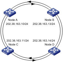
Figure 1-1 Network diagram for RPR port configuration
![]() Caution:
Caution:
When you establish an RPR, the RPR eastbound physical port of a device need to be connected to the westbound physical port of the neighboring device. The names of the two RPR physical ports on a device (that is, the westbound port and the right port) are determined by their positions on the device.
III. Configuration procedure
The following section takes Node A configuration as an example. Other node configurations are similar.
# Add RPR port 2/1/1 to VLAN 2.
[NodeA] vlan 2
[NodeA-vlan2] interface Vlan-interface 2
[NodeA-Vlan-interface2] ip address 202.38.163.10 255.255.255.0
[NodeA-Vlan-interface2] quit
[NodeA] vlan 2
[NodeA-Vlan2] port RprPos 2/1/1
1.3 RPR Layer 2 Tunnel Overview
In the current RPR data forwarding mode, the protocol forwards Layer 2 traffic in flooding mode, that is, broadcasts traffic on the ring. In this mode, every node replicates one copy to itself when receiving a packet and then continues to forward this packet until this packet goes back to the source node. As a result, this forwarding mode occupies much of the RPR ring bandwidth and reduces the utilization rate of ring bandwidth. In order to better utilize the high bandwidth of RPR rings, a tunnel mode is designed for Layer 2 packets to be sent to the destination directly in unicast mode.
& Note:
l GE RPR ports do not support Layer 2 tunneling. However, a GE RPR port still can unicast the packets to the destination station through user MAC address learning.
l 10G RPR and 2.5G RPR ports support Layer 2 tunneling and user MAC address learning. For the packets to the same destination, Layer 2 tunneling is preferred.
l Distributed RPR does not support Layer 2 tunneling.
1.3.1 RPR Layer 2 Tunnel Configuration
When RPR Layer 2 tunnels are configured, each station in the ring network must be equipped with 10G RPR or 2.5G RPR boards uniformly. Configure RPR Layer 2 tunnels after configuring RPR rings.
l Assigning a name to an RPR station (optional)
l Adding an RPR port to a VLAN
l Configuring an RPR Layer 2 tunnel
1.3.2 Procedure of RPR Layer 2 Tunnel Configuration
Follow these steps to configure an RPR Layer 2 tunnel:
|
To do… |
Use the command… |
Remarks |
|
Enter system view |
system-view |
— |
|
Enter RPR logical interface view |
interface RprPos interface-number |
Required To enter physical port view, you need to add “.1” or “.2” to the end of the logical interface name. |
|
Assign a name to the RPR station |
rpr station-name string |
Optional |
|
Configure the RPR port as a trunk port |
port link-type trunk |
Required |
|
Add the RPR port to a VLAN |
port trunk permit vlan vlan-id |
Required |
|
Configure an RPR Layer 2 tunnel |
rpr tunnel vlan vlanid [ range number ] dest-mac mac-address { ringlet0 | ringlet1 } |
Required |
|
Display the information about an RPR Layer 2 tunnel |
display rpr tunnel-table [ vlan vlanid [ range number ] ] [ invalid | valid ] [ RprPos interface-number ] |
This command can be executed in any view. |
1.3.3 RPR Layer 2 Tunneling Configuration Example
I. Network requirements
H3C A, H3C B, H3C C and H3C D form a ring through RPR interfaces. Assign the RPR ports of H3C A and H3C C to VLAN 500. Configure station names DUTA, DUTB, DUTC, and DUTD for each station respectively.
II. Network diagram
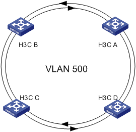
Figure 1-2 Network diagram for RPR Layer 2 tunnel configuration
III. Configuration procedure
1) Configure the switch H3C A.
# Create VLAN 500.
[H3C_A] vlan 500
# Add RPR ports and GE ports to this VLAN.
[H3C_A-vlan500] port GigabitEthernet 2/1/1
[H3C_A-vlan500] quit
[H3C_A] interface RprPos 4/1/1
[H3C_A-RprPos4/1/1] port link-type trunk
[H3c_A-RprPos] undo port trunk permit vlan 1
[H3C_A-RprPos4/1/1] port trunk permit vlan 500
# Configure the station name DUTA for this RPR station.
[H3C_A-RprPos4/1/1] rpr station-name DUTA
# Configure a tunnel to DUTC.
[H3C_A-RprPos4/1/1] rpr tunnel vlan 500 dest-mac 00e0-fc01-0101 ringlet0
2) Configure the switch H3C C.
# Create VLAN 500.
[H3C_C] vlan 500
# Add RPR ports and GE ports to this VLAN.
[H3C_C-vlan500] port GigabitEthernet 2/1/1
[H3C_C-vlan500] quit
[H3C_C] interface RprPos 4/1/1
[H3C_C-RprPos4/1/1] port link-type trunk
[H3c_A-RprPos] undo port trunk permit vlan 1
[H3C_C-RprPos4/1/1] port trunk permit vlan 500
# Configure the station name DUTC for this RPR station.
[H3C_C-RprPos4/1/1] rpr station-name DUTC
# Configure a tunnel to DUTA.
[H3C_C-RprPos4/1/1] rpr tunnel vlan 500 dest-mac 00e0-fc01-0103 ringlet0
IV. Effect verification
Send Layer 2 packets from switch A and switch C to each other. Check the port counts of switch A, switch B, switch C and switch D. It is found that Layer 2 packets have not been broadcast on the ring and there are packet counts on logical interfaces of switch A and switch C instead of on switch B and switch D.
1.4 Troubleshooting
Symptom 1: The topology structure of a RPR ring is not complete.
Solution:
l Check whether physical links are connected correctly and whether uniform optical modules are used.
l Check whether the types of RPR physical ports consistent.
l Check to see if the RPR eastbound physical port is connected to the RPR westbound physical port.
Symptom 2: RPR Layer 2 tunnels do not take effect.
1.5 Displaying and Maintaining RPR Port Configuration
Follow these steps to display and maintain RPR port configuration:
|
To do… |
Use the command… |
Remarks |
|
Enable RPR debugging |
debugging rpr { all | topology | protection | controlframe | mac | ringselection | tp-frame | l2tunnel | vrrp } |
By default, RPR debugging is disabled. |
|
Display port configuration |
display interface [ interface-type | interface-type interface-number ] |
— |
|
Display all RPR defects |
display rpr defect [ { RprPos | Rpr10GE | RprGE } interface-number ] |
— |
|
Display configurable RPR fairness parameter values |
display rpr fairness [ { RprPos | Rpr10GE | RprGE } interface-number ] |
— |
|
Display protection information |
display rpr protection [ { RprPos | Rpr10GE | RprGE } interface-number ] |
If you do not specify a port, the command displays the protection state information about all RPR ports. |
|
Display integrated ring selection table information |
display rpr rs-table { overall | static | dynamic | vrrp } [ { RprPos | Rpr10GE | RprGE } interface-number ] |
Without any parameter, the command displays integrated ring selection table information about all RPR rings by default. |
|
Display all configurable RPR timer values |
display rpr timers [ { RprPos | Rpr10GE | RprGE } interface-number ] |
— |
|
Display topology information |
display rpr topology { all | ring | local | stations } [ verbose ] [ { RprPos | Rpr10GE | RprGE } interface-number ] |
If you do not specify a port, the command displays the topology information about all RPR ports. |
|
Display the traffic statistics information of packets from other nodes on the ring to the local node or from the local node to other nodes |
display rpr statistics { dmac | smac } mac address [ { RprPos | Rpr10GE | RprGE } interface-number ] |
— |
|
Display the statistics of different types of packets sent, received, and forwarded through the specified station. |
display rpr counters [ transit | host | total ] [ { RprPos | Rpr10GE | RprGE } interface-number ] |
— |
|
Display the information about the user MAC addresses and RPR station MAC addresses learnt |
display rpr mac [ count | vlan-id vlan-id | eth-mac user-mac-addr | rpr-mac rpr-mac-addr | { RprPos | Rpr10GE | RprGE } interface-name ] |
— |
Chapter 2 RPR Layer 2 Extended Application Configuration
When configuring RPR Layer 2 extended applications, go to these sections for information you are interested in:
l RPR Layer 2 Tunnel-BAS Collaboration
l RPR Tunnel-Ringlet Force Binding
2.1 RPR Layer 2 Tunnel-BAS Collaboration
2.1.1 Introduction
When transmitted over an RPR, Layer 2 packets can be unicast through tunnels. When a broadband access server (BAS) is connected to a node of an RPR, Layer 2 traffic can be unicast to the node through a Layer 2 tunnel.
To improve reliability, link redundancy can be introduced for a BAS. You can achieve this by connecting the BAS to two RPR stations, one of which is the active and the other is the standby. The built-in link redundancy mechanism of the BAS ensures that only one link is UP at a time. The RPR devices detect link status and release the information about the reachability of the corresponding tunnels, thereby automatically configuring the tunnel egress station and updating the Layer 2 tunnels timely. When the active node fails, the system shuts down the corresponding port the BAS connects to according to system configuration and notifies the BAS to switch to the standby link. As for other stations on the RPR, they can also detect the problem and switch their egress stations accordingly, thus recovering data streams timely.
2.1.2 RPR Layer 2 Tunnel-BAS Collaboration Configuration
![]() Caution:
Caution:
RPR Layer 2 tunnel-BAS collaboration is not supported on distributed RPR. For information about distributed RPR, refer to Distributed RPR Configuration.
RPR tunnel-BAS collaboration is based on a Layer 2 tunnel. To implement RPR tunnel-BAS collaboration, you need to bind the related ports as well as create the corresponding Layer 2 tunnels. The two configurations (that is, binding ports and creating Layer 2 tunnels) can be performed separately.
Follow these steps to configure RPR Layer 2 tunnel-BAS collaboration:
|
To do… |
Use the command… |
Remarks |
|
Enter system view |
system-view |
— |
|
Enter RPR logical interface view |
interface { RprPos | Rpr10GE } interface-number |
Required To enter physical port view, you need to add “.1” and “.2” to the end of the logical interface name. |
|
Assign a name to the RPR station |
rpr station-name string |
Optional |
|
Configure the RPR port as a trunk port |
port link-type trunk |
Required |
|
Add the RPR port to a VLAN |
port trunk permit vlan vlan-id |
Required |
|
Quit to system view |
quit |
— |
|
Create an RPR Layer 2 tunnel |
rpr tunnel vlan vlanid [ range number ] dest-mac mac-address [ priority priority ] [ mac-address [ priority priority ] ] { ringlet0 | ringlet1 } |
Optional |
|
Display the information about the RPR Layer 2 tunnel created |
display rpr tunnel-table [ vlan vlanid [ range number ] ] [ invalid | valid ] [ interface-type interface-number ] |
Optional This command can be executed in any view. |
|
Enter RPR port view |
interface interface-type interface-number |
Required |
|
Configure the RPR port as a trunk port |
port link-type trunk |
Required |
|
Add the RPR port to a VLAN |
port trunk permit vlan vlan-id |
Required |
|
Quit to system view |
quit |
Required |
|
Configure RPR Layer 2 tunnel-BAS collaboration |
rpr tunnel track interface-type interface-number to interface-type interface-number vlan vlan-list [ trigger-shutdown ] |
Required |
|
Display the information about RPR Layer 2 tunnel-BAS collaboration |
display rpr tunnel-track { all | rpr-interface interface-type interface-number [ to bas-interface interface-type interface-number ] } |
Optional This command can be executed in any view. |
& Note:
l As aggregation link state detecting is currently not supported, do not specify the member port of an aggregation port as a BAS port.
l You are recommended to disable STP on BAS ports to prevent the latter from participating in STP calculation.
l Use the trigger-shutdown keyword of the rpr tunnel track command according to the link backup mechanism invoked by the BAS.
l If you execute the rpr tunnel vlan command with the monitor-port keyword specified, the collaboration function automatically shuts down the corresponding BAS port when a ringlet fails and brings up the port when the ringlet recovers. The command is of higher priority than the shutdown command and undo shutdown command on the BAS port.
l Do not configure the loopback internal command on an RPR logical interface with RPR tunneling configured or on the BAS port corresponding to the RPR logical interface. Otherwise, the track function of RPR tunneling may operate improperly.
2.1.3 Configuration Example
I. Network requirements
Switch A, Switch B, Switch C, and Switch D form a ring network. Switch A is connected with a digital subscriber line access multiplexer (DSLAM). The data stream of VLAN 2 through VLAN 300 is forwarded from Switch C to a BAS through a tunnel established on the ring network. Switch B serves as a backup station of the tunnel. When an RPR port on Switch B or Switch C operates improperly, it is required that the corresponding port connected with the BAS be shut down. The four stations are named DUTA, DUTB, DUTC, and DUTD.
II. Network diagram
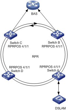
Figure 2-1 Network diagram for RPR tunnel-BAS collaboration
III. Configuration procedure
l Configure Switch A.
# Create VLAN 2 through VLAN 300.
<H3C> system-view
[H3C] vlan 2 to 300
# Configure the RPR port and the GE port as trunk ports that permit packets of VLAN 2 through VLAN 300.
[H3C] interface GigabitEthernet 2/1/1
[H3C-GigabitEthernet2/1/1] port link-type trunk
[H3C-GigabitEthernet2/1/1] undo port trunk permit vlan 1
[H3C-GigabitEthernet2/1/1] port trunk permit vlan 2 to 300
[H3C-GigabitEthernet2/1/1] quit
[H3C] interface RprPos 4/1/1
[H3C-RprPos4/1/1] port link-type trunk
[H3C-RprPos4/1/1] undo port trunk permit vlan 1
[H3C-RprPos4/1/1] port trunk permit vlan 2 to 300
# Configure the name of the RPR station as DUTA.
[H3C-RprPos4/1/1] rpr station-name DUTA
# Configure a tunnel leading to DUTC, with DUTB as a backup station.
[H3C-RprPos4/1/1] rpr tunnel vlan 2 range 299 dest-mac 00e0-fc01-0101 priority 1 00e0-fc01-0102 priority 0 ringlet0
l Configure Switch C.
# Create VLAN 2 through VLAN 300.
<H3C> system-view
[H3C] vlan 2 to 300
# Configure the RPR port and the GE port as trunk ports that permits the packets of VLAN 2 through VLAN 300.
[H3C] interface GigabitEthernet2/1/1
[H3C-GigabitEthernet2/1/1] port link-type trunk
[H3C-GigabitEthernet2/1/1] undo port trunk permit vlan 1
[H3C-GigabitEthernet2/1/1] port trunk per vlan 2 to 300
[H3C-GigabitEthernet2/1/1] quit
[H3C] interface RprPos 4/1/1
[H3C-RprPos4/1/1] port link-type trunk
[H3C-RprPos4/1/1] undo port trunk permit vlan 1
[H3C-RprPos4/1/1] port trunk permit vlan 2 to 300
# Configure the name of the RPR station as DUTC.
[H3C-RprPos4/1/1] rpr station-name DUTC
# Configure a tunnel leading to DUTA.
[H3C-RprPos4/1/1] rpr tunnel vlan 2 range 299 dest-mac 00e0-fc01-0103 ringlet0
# Bind the tunnel created for VLAN 2 through VLAN 300 to GigabitEthernet 2/1/1.
[H3C] rpr tunnel track GigabitEthernet2/1/1 to RprPos 4/1/1 vlan 2 to 300 trigger-shutdown
l Configure Switch B.
# Create VLAN 2 through VLAN 300.
<H3C> system-view
[H3C] vlan 2 to 300
# Configure the RPR port and the GE port as trunk ports that permit packets of VLAN 2 through VLAN 300.
[H3C] interface GigabitEthernet2/1/1
[H3C-GigabitEthernet2/1/1] port link-type trunk
[H3C-GigabitEthernet2/1/1] undo port trunk permit vlan 1
[H3C-GigabitEthernet2/1/1] port trunk per vlan 2 to 300
[H3C-GigabitEthernet2/1/1] quit
[H3C] interface RprPos 4/1/1
[H3C-RprPos4/1/1] port link-type trunk
[H3C-RprPos4/1/1] undo port trunk permit vlan 1
[H3C-RprPos4/1/1] port trunk permit vlan 2 to 300
# Configure the name of the RPR station as DUTB.
[H3C-RprPos4/1/1] rpr station-name DUTB
# Configure a tunnel leading to DUTA.
[H3C-RprPos4/1/1] rpr tunnel vlan 2 range 299 dest-mac 00e0-fc01-0103 ringlet0
# Bind the tunnel created for VLAN 2 through VLAN 300 to GigabitEthernet 2/1/1.
[H3C] rpr tunnel track GigabitEthernet2/1/1 to RprPos4/1/1 vlan 2 to 300 trigger-shutdown
2.2 RPR Tunnel-Ringlet Force Binding
2.2.1 Introduction
A ringlet can be configured with preference for an RPR Layer 2 tunnel. When this ringlet fails, the data flow automatically changes to an available ringlet. As shown in Figure 2-2, Switch A, Switch B, Switch C, Switch D, and Switch E form an RPR. The data travels through PE, Switch A, Switch B, to P1. After the link between Switch A and Switch B fails, the data travels through Switch A, Switch E, Switch D, Switch C, Switch B to P1.
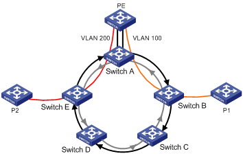
Figure 2-2 RPR tunnel-ringlet force binding
However, data may be expected to go through PE, Switch A, Switch E and P2 when the link between Switch A and Switch B goes down (see Figure 2-2). To implement the forwarding path, you can configure tunnel-ringlet force binding:
l When a ringlet fails, the traffic in the tunnel is discarded directly and the BAS port, if configured, is shut down automatically.
l After the ringlet becomes available again, the tunnel carries traffic again and the BAS port, if configured, is brought up automatically.
2.2.2 Tunnel-Ringlet Force Binding Configuration
Follow these steps to configure RPR tunnel-ringlet force binding:
|
To do… |
Use the command… |
Remarks |
|
Enter system view |
system-view |
— |
|
Enter RPR logical interface view |
interface RprPos interface-number |
Required To enter physical port view, you need to add “.1” and “.2” to the end of the logical interface name. |
|
Assign a name to the RPR station |
rpr station-name string |
Optional |
|
Configure the RPR port as a trunk port |
port link-type trunk |
Required By default, the RPR port is an access port. |
|
Add the RPR port to a VLAN |
port trunk permit vlan vlan-id |
Required |
|
Quit to system view |
quit |
— |
|
Configure an RPR Layer 2 tunnel |
rpr tunnel vlan vlanid dest-mac mac-address { ringlet0 | ringlet1 } force-ringlet [ monitor-port interface-type interface-name ] |
Required Only Ethernet ports can be collaboration ports. By default, packets of VLANs are not configured to be tunneled to a destination station. |
|
Display the information about an RPR Layer 2 tunnel |
display rpr tunnel-table [ vlan vlanid [ range number ] ] [ valid | invalid ] [ interface-type interface-number ] |
This command can be executed in any view. |
& Note:
l Do not specify the member port of an aggregation port as a collaboration port.
l Make sure one collaboration port maps to only one VLAN tunnel.
l If you execute the rpr tunnel vlan command with the monitor-port keyword specified, when a ringlet fails, the collaboration function automatically shuts down the corresponding collaboration port. The command is of higher priority than the shutdown command and undo shutdown command on the collaboration port.
l Do not configure the loopback internal command on a collaboration port with RPR tunnel-ringlet force binding configured. Otherwise, the force binding function of RPR tunneling may operate improperly.
l If tunnel-ringlet force binding and a collaboration port are both configured, do not replace the service board where the collaboration port is configured when the RPR service board is not in place.
2.2.3 Configuration Example
I. Network requirements
l Switch A, Switch B, Switch C, Switch D, and Switch E form an RPR.
l Switch A connects to the upstream device PE through two links, one for VLAN 100 and the other for VLAN 200. GigabitEthernet 2/1/1 belongs to VLAN 100 and GigabitEthernet 2/1/2 belongs to VLAN 200.
l The link for VLAN 100 is an optimal path and the data travels through PE, Switch A, Switch B, and P1.
l Configure tunnel-ringlet force binding so that the data is forwarded through VLAN 200 to P2 if the link between Switch A and Switch B fails.
II. Network diagram

Figure 2-3 Network diagram for RPR tunnel-ringlet force binding
III. Configuration procedure
1) Configuration on Switch A
# Create VLAN 100 and VLAN 200.
<H3C> system-view
[H3C] vlan 100
[H3C-vlan100] quit
[H3C] vlan 200
[H3C-vlan200] quit
# Assign GigabitEthernet 2/1/1 to VLAN 100 and GigabitEthernet 2/1/2 to VLAN 200.
[H3C] interface GigabitEthernet 2/1/1
[H3C-GigabitEthernet2/1/1] port link-type trunk
[H3C-GigabitEthernet2/1/1] undo port trunk permit vlan 1
[H3C-GigabitEthernet2/1/1] port trunk permit vlan 100
[H3C-GigabitEthernet2/1/1] quit
[H3C] interface GigabitEthernet 2/1/2
[H3C-GigabitEthernet2/1/2] port link-type trunk
[H3C-GigabitEthernet2/1/2] undo port trunk permit vlan 1
[H3C-GigabitEthernet2/1/2] port trunk permit vlan 200
[H3C-GigabitEthernet2/1/2] quit
# Assign RPRPOS 4/1/1 to VLAN 100 and VLAN 200.
[H3C] interface RprPos 4/1/1
[H3C-RprPos4/1/1] port link-type trunk
[H3C-RprPos4/1/1] undo port trunk permit vlan 1
[H3C-RprPos4/1/1] port trunk permit vlan 100 200
# Configure this RPR station name as station.
[H3C-RprPos4/1/1] rpr station-name station
# Configure packets of VLAN 100 to be tunneled to the destination address station, bind tunnel to ringlet0 and configure GigabitEthernet 2/1/1 as a collaboration port.
[H3C-RprPos4/1/1] rpr tunnel vlan 100 dest-mac 00e0-fc01-0101 ringlet0 force-ringlet monitor-port GigabitEthernet2/1/1
# Configure packets of VLAN 200 to be tunneled to the destination address station, bind tunnel to ringlet1 and configure GigabitEthernet 2/1/2 as a collaboration port.
[H3C-RprPos4/1/1] rpr tunnel vlan 200 dest-mac 00e0-fc01-0102 ringlet1 force-ringlet monitor-port GigabitEthernet2/1/2
IV. Verification
# Display traffic information about VLAN 100 and VLAN 200 on switches.
1) In normal condition, Switch B receives traffic from VLAN 100.
2) In case of link failure between Switch A and Switch B, GigabitEthernet 2/1/1 on Switch A automatically shuts down and GigabitEthernet 2/1/2 automatically goes up so that traffic from VLAN 100 is forwarded through VLAN 200. Thus VLAN 100 on Switch B carries no data while VLAN 200 on Switch E carries data.
Chapter 3 VRRP over RPR Configuration
When configuring VRRP over RPR, go to these sections for information you are interested in:
3.1 Introduction
RPR is a high-reliability ring-network technology. With RPR employed, link switchover can be completed within 50 ms. You can employ RPR in a VRRP (virtual router redundancy protocol) group to ensure upstream transmission on RPR stations. In a VRRP group, link switchover can be completed in seconds. However, with RPR employed in it, the link switchover period can be reduced to millisecond-level.
In actual use, an RPR intersecting ring topology is adopted for networking. The two RPRs reside in different VLANs. Packets between them are forwarded on Layer 3. Static routes are configured on the rings, with the next hop configured as the virtual VRRP address. VRRP-RPR collaboration groups are configured on VRRP-enabled devices for them to monitor the VRRP status of each other. If the active VRRP station fails, the standby station takes the place of it and sends VRRP ring selection messages. The data streams of other stations on the ring are redirected to the standby station. You can employ RPR in a VRRP group without modifying user configuration.
3.1.1 Basic Concepts of VRRP over RPR
I. Basic concepts of VRRP
VRRP can group a set of routers in an LAN into a backup group, which functions as a virtual router. A VRRP group contains a master router and multiple backup routers.
In a VRRP group, the role (that is, the master router or backup router) a router plays is determined by its priority. The master router has the highest priority.
A VRRP group provides monitor interfaces, which extends the backup function. It provides redundancy for both local interfaces and interfaces of other routers in the VRRP group. When a monitored interface goes down, the priority of the router owning the interface decreases by a specific value. If the router is currently the master router, priority decrement occurred on it may trigger another router in the VRRP group to become the master router.
II. Basic concepts of RPR
RPR operates on Layer 2 of the OSI (open system interconnection) protocol stack. It enables flexible and effective MAN solutions.
RPR delivers carrier-class reliability. It can carry out data-oriented services and can provide integrated transmission solutions for multi-service transfer.
3.1.2 Work Mechanism of VRRP over RPR
On an RPR network, create a VRRP group on each of the two intersecting stations, with the next hop of the corresponding egress device being the virtual IP address of the VRRP group. Configure monitor interfaces in the VRRP groups, with one VRRP group being the target of the monitor interface in the other VRRP group. In this way, the VRRP can switch bidirectional traffic in case a port at one side is down.
Fast switching is triggered when any of the following occurs.
l A power failure occurs on the active device, the RPR card is unplugged, or the fiber connecting the ports of the RPR card on the active device is disconnected.
l A monitor interface is disconnected.
l An RPR logical interface is shut down.
l The interface of the VLAN where an RPR logical interface is located is down.
l The priority of a VRRP group is changed.
& Note:
In VRRP over RPR configuration, the VRRP group can contain only two stations.
3.2 VRRP over RPR Configuration
![]() Caution:
Caution:
l Refer to Configuration Example for networking. Otherwise, the switching time may exceed 50 ms.
l VRRP over RPR does not support distributed RPR configuration. For information about distributed RPR, refer to Distributed RPR Configuration.
Follow these steps to configure VRRP over RPR:
|
To do… |
Use the command… |
Remarks |
|
Enter system view |
system-view |
— |
|
Create a VLAN |
vlan vlan-id |
Required |
|
Add an RPR port to the VLAN |
port { RprPos | Rpr10GE } interface-number |
Required |
|
Create a VLAN interface |
interface vlan-interface vlan-id |
Required |
|
Assign an IP address to the VLAN interface |
ip address ip-address ip-mask |
Required |
|
Create a VRRP group |
vrrp vrid virtual-router-id virtual-ip virtual-address |
Required |
|
Configure the VRRP group priority |
vrrp vrid virtual-router-id priority priority |
Required When configuring VRRP over RPR, make sure that the configured VRRP priority values are different. Otherwise, switching may fail. |
|
Configure a monitored port for a VRRP group |
vrrp vrid virtual-router-id track interface interface-type interface-number [ reduced priority-reduced ] |
Required |
|
Enter RPR logical interface view |
Interface { RprPos | Rpr10GE }interface-number |
Required To enter physical port view, you need to add “.1” and “.2” to the end of the logical interface name. |
|
Configure an RPR VRRP collaboration group |
rpr vrrp vlan vlan-id vrid vrid-id [ mate h-h-h ] group group-id |
Required |
|
Display an RPR VRRP collaboration group |
display rpr vrrp [ interface-type interface-number ] [ group group-id ] |
This command can be executed in any view. |
3.2.1 Configuration Example
I. Network requirements
Connect the RPR ports of Node A, Node B, Node C, and Node D using fibers to form two intersecting rings. Node A and Node D are egress devices. Create two VRRP groups on the two RPRs where Node B and Node C are located. Bind the RPR logical interfaces of Node B and Node C to the corresponding VRRP groups. In this way, link redundancy for the bidirectional traffic between Node A and Node D can be implemented through the VRRP groups comprised of Node B and Node C.
II. Network diagram

Figure 3-1 Network diagram for VRRP over RPR configuration
III. Configuration procedure
Following are the configurations performed on Node B and Node C, which creates VRRP groups on the corresponding RPR rings, configures monitor interfaces, and binds RPR ports to the corresponding VRRP groups.
l Configure Node B
# Create VRRP groups on VLAN-interface 10 and VLAN-interface 20. Configure two monitor interfaces to monitor their ports mutually.
<H3C> system-view
System View: return to User View with Ctrl+Z.
[H3C] vlan 10
[H3C-vlan10] port RprPos4/1/1
[H3C-vlan10] interface Vlan-interface 10
[H3C-Vlan-interface10] ip address 10.10.10.10 255.255.255.0
[H3C-Vlan-interface10] vrrp vrid 10 virtual-ip 10.10.10.1
[H3C-Vlan-interface10] vrrp vrid 10 priority 200
[H3C-Vlan-interface10] vrrp vrid 10 track interface Vlan-interface20 reduced 255
[H3C-Vlan-interface10] quit
[H3C] vlan 20
[H3C-vlan20] port RprPos7/1/1
[H3C-vlan20] interface Vlan-interface 20
[H3C-Vlan-interface20] ip address 20.20.20.10 255.255.255.0
[H3C-Vlan-interface20] vrrp vrid 20 virtual-ip 20.20.20.1
[H3C-Vlan-interface20] vrrp vrid 20 track interface Vlan-interface10 reduced 255
# Configure static routes.
[H3C] ip route-static 30.0.0.0 24 10.10.10.30
[H3C] ip route-static 40.0.0.0 24 20.20.20.30
# Associate the RPR ports with the VRRP groups as follows. Bind RPRPOS 4/1/1 to VRRP group 10 (assuming that the MAC address of the adjacent node, Node C, is 00e0-fc5a-edbc). Bind RPRPOS 7/1/1 to VRRP group 20.
[H3C] interface RprPos4/1/1
[H3C-RprPos4/1/1] Rpr vrrp vird 10 vlan 10 mate 00e0-fc5a-edbc group 1
[H3C-RprPos4/1/1] interface RprPos7/1/1
[H3C-RprPos7/1/1] Rpr vrrp vird 20 vlan 20 mate 00e0-fc5a-edbc group 1
l Configure Node C
# Create VRRP groups on VLAN-interface10 and VLAN-interface20. Configure two monitor interfaces to monitor their ports mutually.
<H3C> system-view
System View: return to User View with Ctrl+Z.
[H3C] vlan 10
[H3C-vlan10] port RprPos3/1/1
[H3C-vlan10] interface Vlan-interface 10
[H3C-Vlan-interface10] ip address 10.10.10.20 255.255.255.0
[H3C-Vlan-interface10] vrrp vrid 10 virtual-ip 10.10.10.1
[H3C-Vlan-interface10] vrrp vrid 10 track interface Vlan-interface20 reduced 255
[H3C-Vlan-interface10] quit
[H3C] vlan 20
[H3C-vlan20] port RprPos7/1/1
[H3C-vlan20] interface Vlan-interface 20
[H3C-Vlan-interface20] ip address 20.20.20.20 255.255.255.0
[H3C-Vlan-interface20] vrrp vrid 20 virtual-ip 20.20.20.1
[H3C-Vlan-interface20] vrrp vrid 20 priority 200
[H3C-Vlan-interface20] vrrp vrid 20 track interface Vlan-interface10 reduced 255
# Configure static routes.
[H3C] ip route-static 30.0.0.0 24 10.10.10.30
[H3C] ip route-static 40.0.0.0 24 20.20.20.30
# Associate the RPR ports with the VRRP groups as follows. Bind RPRPOS 3/1/1 to VRRP group 10 (assuming that the MAC address of the adjacent node, Node B, is 00e0-fc01-8504). Bind RPRPOS 7/1/1 to VRRP group 20.
[H3C] interface RprPos3/1/1
[H3C-RprPos3/1/1] Rpr vrrp vird 10 vlan 10 mate 00e0-fc01-8504 group 1
[H3C-RprPos3/1/1] interface RprPos7/1/1
[H3C-RprPos7/1/1] Rpr vrrp vird 20 vlan 20 mate 00e0-fc01-8504 group 1
l Configure Node A
<H3C> system-view
System View: return to User View with Ctrl+Z.
[H3C] vlan 30
[H3C-vlan30] port GigabitEthernet 1/1/1
[H3C-vlan30] interface Vlan-interface 30
[H3C-Vlan-interface30] ip address 30.0.0.1 24
[H3C-Vlan-interface30] vlan 10
[H3C-vlan10] port RprPos4/1/1
[H3C-vlan10] interface Vlan-interface 10
[H3C-Vlan-interface10] ip address 10.10.10.30 24
[H3C-Vlan-interface10] quit
[H3C] ip route-static 40.0.0.0 24 10.10.10.1
[H3C] ip route-static 20.20.20.0 24 10.10.10.1
l Configure Node D
<H3C> system-view
System View: return to User View with Ctrl+Z.
[H3C] vlan 40
[H3C-vlan40] port GigabitEthernet 1/1/1
[H3C-vlan40] interface Vlan-interface 40
[H3C-Vlan-interface40] ip address 40.0.0.1 24
[H3C-Vlan-interface40] vlan 20
[H3C-vlan20] port RprPos4/1/1
[H3C-vlan20] interface Vlan-interface 20
[H3C-Vlan-interface20] ip address 20.20.20.30 24
[H3C-Vlan-interface20] quit
[H3C] ip route-static 30.0.0.0 24 20.20.20.1
[H3C] ip route-static 10.10.10.0 24 20.20.20.1
Display the information about RPR and VRRP on Node B.
<H3C> display rpr vrrp RprPos4/1/1 group 1
Group ID : 1
Interface : RprPos4/1/1
Vlan ID : 10
VRID : 10
Mate MAC : 00e0-fc5a-edbc
State : Master
Local Pri : 200 Remote Pri : 100
<H3C> display rpr vrrp RprPos7/1/1 group 1
Group ID : 1
Interface : RprPos7/1/1
Vlan ID : 20
VRID : 20
Mate MAC : 00e0-fc5a-edbc
State : Slave
Local Pri : 100 Remote Pri : 200
![]() Caution:
Caution:
l To achieve faster switching, configure different devices as the master devices of the two VRRP groups. Therefore, when a master device fails, only the master node of one VRRP group needs to be switched.
l You need to configure static routes for the other nodes in the ring to make sure that the next hop of the routes is a virtual VRRP address.
l If the upper-layer VRRP state is inconsistent with the lower-layer RPR status in a collaboration group, remove the collaboration group and then configure the group again to restore it.
l You are recommended to configure only one RPR logical interface for the VLAN where the VRRP group resides.
Chapter 4 RPR Intersecting Rings Configuration
When configuring RPR intersecting rings, go to these sections for information you are interested in:
l RPR Intersecting Rings Configuration
4.1 Introduction
4.1.1 RPR Intersecting Rings Overview
RPR intersecting rings are designed to avoid Layer 2 loops. This feature supports multiple instances to implement load-sharing per service, and each instance can bind to a collaboration port. RPR intersecting rings support one master and six slave rings at most.
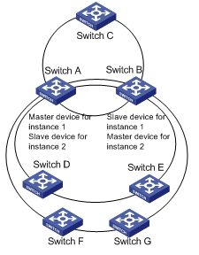
Figure 4-1 Sample network diagram for RPR intersecting rings
Each intersecting ring instance consists of a master device and a slave device. As shown in Figure 4-1, Switch A and Switch B are intersecting stations. For instance 1 Switch A is the master device and Switch B is the slave device while for instance 2, Switch A is slave and Switch B is master.
The master device forwards data and when the collaboration port on the master device or the port on the master ring fails, the master device turns to be a slave device and tells its neighbor (two intersecting stations are neighbors) to act a master device for data forwarding. However, if the slave ring on the master device fails, switching will not occur and the slave port on the slave device forwards data.
4.1.2 Master and Slave Role Calculation
Four factors decide master and salve role calculation for an intersecting ring instance in descending order: status of the collaboration port, status of the master ring port, master and slave configurations for the instance, and MAC address of the station.
1) The intersecting station with an UP collaboration port becomes the master device.
2) If the status of the collaboration ports on both intersecting stations are the same, the status of the master ring port decides.
3) If the status of the master ring ports are the same, then the master and slave configurations for the instance decide.
4) If the first three conditions are the same, then the station with the higher MAC address becomes the master device.
4.2 RPR Intersecting Rings Configuration
![]() Caution:
Caution:
l At present, only two intersecting stations are supported for RPR intersecting rings,
l RPR intersecting rings are not supported on a GE RPR board.
l The intersecting devices in the RPR intersecting rings do not support distributed RPR.
Follow these steps to configure RPR intersecting rings:
|
To do… |
Use the command… |
Remarks |
|
Enter system view |
system-view |
— |
|
Specify a neighbor for the current device |
rpr cross-ring neighbour mac-address |
Required |
|
Create an intersecting ring instance and bind the intersecting ring instance to the specified STP instance |
rpr cross-ring instance instance-id { primary | secondary } stp-instance stp-instance-id |
Required Up to 6 instances can be created. |
|
Specify a port as the collaboration port for the specified RPR intersecting ring instance |
rpr cross-ring instance instance-id track interface-type interface-number |
Optional |
|
Enter RPR logical interface view |
interface { RprPos | Rpr10GE } interface-number |
— |
|
Configure the ring as a master or slave ring |
rpr cross-ring { master | slave } |
Optional By default, an RPR logical interface is not configured as a master or slave ring. An RPR logical interface cannot be configured as both the master ring and a slave ring at the same time. |
|
Configure the backup ring for the specified intersecting ring instance(s) |
rpr cross-ring slave backup-ring instance instance-id1 [ to instance-id2 ] |
Optional This command also specifies the RPR logical interface as a slave ring of the intersecting rings. |
|
Display the basic configuration and instance information of the specified or all intersecting ring instances |
display rpr cross-ring instance { instance-id | all } |
This command can be executed in any view. |
|
Display defects of intersecting RPR rings |
display rpr cross-ring defect |
This command can be executed in any view. |
|
Display information about the backup rings of the intersecting RPR rings |
display rpr cross-ring backup-ring |
This command can be executed in any view. |
|
Enable debugging for events of intersecting RPR rings |
debugging rpr cross-ring event |
Disabled by default |
|
Enable debugging for all protocol packets of intersecting RPR rings |
debugging rpr cross-ring packet { all | nsn | nrc | psc | flushmac } |
Disabled by default |
& Note:
l The member port of an aggregation group can serve as the collaboration port of an instance. However, only the status of this port rather than the status of the aggregation group participates in the role calculation.
l If RPR tunnel-BAS collaboration is configured on the intersecting ring's collaboration port, make sure the intersecting ring instance does not contain the VLAN for the tunnel-BAS collaboration.
l Do not configure the bpdu-tunnel command on an RPR logical interface with intersecting rings configured. Otherwise, the loop prevention function of RPR intersecting rings may operate improperly.
l Do not configure the loopback internal command on an RPR logical interface with RPR intersecting rings configured or on the collaboration port corresponding to the RPR logical interface. Otherwise, the loop prevention function of RPR intersecting rings may operate improperly.
4.3 Configuration Example
I. Network requirements
l Switch A, Switch B, and Switch C form RPR 1.
l Switch A, Switch B, Switch D, and Switch E form RPR 2.
l Switch A, Switch B, Switch F, and Switch G form RPR 3.
l These three RPRs intersect at Switch A and Switch B.
l Traffic of VLAN 2000 through VLAN 3000 arriving at Switch D goes along RPR 2 and then goes along RPR 1 at Switch B to Switch C.
l Configure intersecting rings so that that the data can go to Switch C through Switch A if the RPR port of Switch B fails. When the RPR port works properly again, the data switch back to Switch B and then Switch C.
l A DSLAM device connects to Switch G. Data of VLAN 2 through VLAN 100 are transferred from Switch A to BAS device and Switch B is a slave station for Switch A. Configure the data to go to BAS device from Switch B when the RPR port or the uplink port on Switch A fails.
II. Network diagram
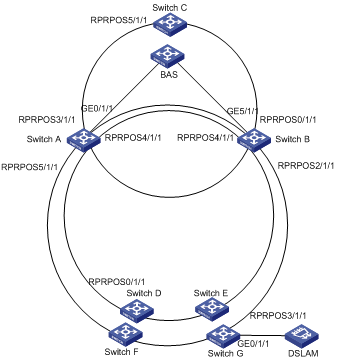
Figure 4-2 Network diagram for RPR intersecting rings
III. Configuration procedure
l Configure Switch A
# Create VLAN 2 through VLAN 100, and VLAN 2000 through VLAN 3000.
<H3C> system-view
[H3C] vlan 2 to 100
[H3C] vlan 2000 to 3000
# Bind STP instance 5 to VLAN 2 through VLAN 100 and STP instance 6 to VLAN 2000 through VLAN 3000.
[H3C] stp region-configuration
[H3C-mst-region] instance 5 vlan 2 to 100
[H3C-mst-region] instance 6 vlan 2000 to 3000
[H3C-mst-region] active region-configuration
[H3C-mst-region] quit
# Assign the RPR ports and GE port to the specified VLANs respectively as required.
[H3C] interface GigabitEthernet0/1/1
[H3C-GigabitEthernet0/1/1] port link-type trunk
[H3C-GigabitEthernet0/1/1] undo port trunk permit vlan 1
[H3C-GigabitEthernet0/1/1] port trunk permit vlan 2 to 100
[H3C-GigabitEthernet0/1/1] quit
[H3C] interface RprPos 3/1/1
[H3C-RprPos3/1/1] port link-type trunk
[H3C-RprPos3/1/1] undo port trunk permit vlan 1
[H3C-RprPos3/1/1] port trunk permit vlan 2 to 100
[H3C-RprPos3/1/1] port trunk permit vlan 2000 to 3000
[H3C-RprPos3/1/1] quit
[H3C] interface RprPos 4/1/1
[H3C-RprPos4/1/1] port link-type trunk
[H3C-RprPos4/1/1] undo port trunk permit vlan 1
[H3C-RprPos4/1/1] port trunk permit vlan 2000 to 3000
[H3C-RprPos4/1/1] quit
[H3C] interface RprPos 5/1/1
[H3C-RprPos5/1/1] port link-type trunk
[H3C-RprPos5/1/1] undo port trunk permit vlan 1
[H3C-RprPos5/1/1] port trunk permit vlan 2 to 100
[H3C-RprPos5/1/1] quit
# Specify Switch B as the neighbor for Switch A.
[H3C] rpr cross-ring neighbor 000e-0123-ee00
# Bind STP instance 5 to intersecting ring instance 1, and STP instance 6 to intersecting ring instance 2. Configure Switch A as the master device of intersecting ring instance 1 and slave device of intersecting ring instance 2.
[H3C] rpr cross-ring instance 1 primary stp-instance 5
[H3C] rpr cross-ring instance 2 secondary stp-instance 6
# Bind intersecting ring instance 1 to uplink port GigabitEthernet 0/1/1.
[H3C] rpr cross-ring instance 1 track GigabitEthernet 0/1/1
# Configure RPRPOS 3/1/1 as the master ring, RPRPOS 4/1/1 and RPRPOS 5/1/1 as the slave rings.
[H3C] interface RprPos3/1/1
[H3C-RprPos3/1/1] stp disable
[H3C-RprPos3/1/1] rpr cross-ring master
[H3C-RprPos3/1/1] quit
[H3C] interface RprPos4/1/1
[H3C-RprPos4/1/1] stp disable
[H3C-RprPos4/1/1] rpr cross-ring slave
[H3C-RprPos4/1/1] quit
[H3C] interface RprPos5/1/1
[H3C-RprPos5/1/1] stp disable
[H3C-RprPos5/1/1] rpr cross-ring slave
l Configure Switch B
# Create VLAN 2 through VLAN 100, and VLAN 2000 through VLAN 3000.
<H3C> system-view
[H3C] vlan 2 to 100
[H3C] vlan 2000 to 3000
# Bind STP instance 5 to VLAN 2 through VLAN 100 and STP instance 6 to VLAN 2000 through VLAN 3000.
[H3C] stp region-configuration
[H3C-mst-region] instance 5 vlan 2 to 100
[H3C-mst-region] instance 6 vlan 2000 to 3000
[H3C-mst-region] active region-configuration
[H3C-mst-region] quit
# Assign the RPR ports and GE port to the specified VLANs respectively as required.
[H3C] interface GigabitEthernet5/1/1
[H3C-GigabitEthernet5/1/1] port link-type trunk
[H3C-GigabitEthernet5/1/1] undo port trunk permit vlan 1
[H3C-GigabitEthernet5/1/1] port trunk permit vlan 2 to 100
[H3C-GigabitEthernet5/1/1] quit
[H3C] interface RprPos 0/1/1
[H3C-RprPos0/1/1] port link-type trunk
[H3C-RprPos0/1/1] undo port trunk permit vlan 1
[H3C-RprPos0/1/1] port trunk permit vlan 2 to 100
[H3C-RprPos0/1/1] port trunk permit vlan 2000 to 3000
[H3C-RprPos0/1/1] quit
[H3C] interface RprPos 2/1/1
[H3C-RprPos2/1/1] port link-type trunk
[H3C-RprPos2/1/1] undo port trunk permit vlan 1
[H3C-RprPos2/1/1] port trunk permit vlan 2 to 100
[H3C-RprPos2/1/1] quit
[H3C] interface RprPos 4/1/1
[H3C-RprPos4/1/1] port link-type trunk
[H3C-RprPos4/1/1] undo port trunk permit vlan 1
[H3C-RprPos4/1/1] port trunk permit vlan 2000 to 3000
# Specify Switch A as the neighbor for Switch B.
[H3C] rpr cross-ring neighbor 000e-02d0-0016
# Bind STP instance 5 to intersecting ring instance 1, and STP instance 6 to intersecting ring instance 2. Configure Switch A as the master device of intersecting ring instance 1 and slave device of intersecting ring instance 2.
[H3C] rpr cross-ring instance 1 secondary stp-instance 5
[H3C] rpr cross-ring instance 2 primary stp-instance 6
# Bind intersecting ring instance 1 to the uplink port GigabitEthernet 5/1/1.
[H3C] rpr cross-ring instance 1 track GigabitEthernet 5/1/1
# Configure RPRPOS 0/1/1 as the master ring, and RPRPOS 2/1/1 and RPRPOS 4 as the slave ring.
[H3C] interface RprPos 0/1/1
[H3C-RprPos0/1/1] stp disable
[H3C-RprPos0/1/1] rpr cross-ring master
[H3C-RprPos0/1/1] quit
[H3C] interface RprPos 2/1/1
[H3C-RprPos2/1/1] stp disable
[H3C-RprPos2/1/1] rpr cross-ring slave
[H3C-RprPos2/1/1] quit
[H3C] interface RprPos 4/1/1
[H3C-RprPos4/1/1] stp disable
[H3C-RprPos4/1/1] rpr cross-ring slave
l Configure Switch C
# Create VLAN 2000 through VLAN 3000.
<H3C> system-view
[H3C] vlan 2000 to 3000
# Assign RPRPOS 5/1/1 to VLAN 2000 through VLAN 3000.
[H3C] interface RprPos 5/1/1
[H3C-RprPos5/1/1] port link-type trunk
[H3C-RprPos5/1/1] undo port trunk permit vlan 1
[H3C-RprPos5/1/1] port trunk permit vlan 2000 to 3000
l Configure Switch D
# Create VLAN 2000 through VLAN 3000.
<H3C> system-view
[H3C] vlan 2000 to 3000
# Assign RPRPOS 0/1/1 to VLAN 2000 through VLAN 3000.
[H3C] interface RprPos 0/1/1
[H3C-RprPos0/1/1] port link-type trunk
[H3C-RprPos0/1/1] undo port trunk permit vlan 1
[H3C-RprPos0/1/1] port trunk permit vlan 2000 to 3000
l Configure Switch G
# Create VLAN 2 through VLAN 100.
<H3C> system-view
[H3C] vlan 2 to 100
# Assign the RPR port and GE port to VLAN 2 though VLAN 100 respectively.
[H3C] interface GigabitEthernet 0/1/1
[H3C-GigabitEthernet0/1/1] port link-type trunk
[H3C-GigabitEthernet0/1/1] undo port trunk permit vlan 1
[H3C-GigabitEthernet0/1/1] port trunk permit vlan 2 to 100
[H3C-GigabitEthernet0/1/1] quit
[H3C] interface RprPos 3/1/1
[H3C-RprPos3/1/1] port link-type trunk
[H3C-RprPos3/1/1] undo port trunk permit vlan 1
[H3C-RprPos3/1/1] port trunk permit vlan 2 to 100
Chapter 5 Distributed RPR Configuration
When configuring distributed RPR, go to these sections for information you are interested in:
l Distributed RPR Configuration
5.1 Introduction
5.1.1 Distributed RPR Overview
RPR is a high-reliability ring-network technology. With RPR employed, link switchover can be completed within 50 ms. The RPR station fails when the card where the two RPR physical ports are located goes down. For better performance, S9500 series implement the distributed RPR feature.
The two physical ports of an RPR station are located on different cards, one active and one standby. When the master card goes down, the slave card takes over to forward traffic.
5.1.2 Distributed RPR Mechanism
Connect two cards of an RPR station in serial mode, one being the active and the other being the standby. These two cards are considered as one RPR station logically. The active card is running RPR while the standby card is in the pass-through state. At the failure of the active card, the standby card takes over to transfer data.
Fast switching is performed in either of the following cases:
l Two physical ports on the active card are both down or the logical interface of the active card is shut down.
l The active card is unplugged.
l The active card restarts.
l The active card has hardware failures.
The distributed RPR configuration is for RPR stations. An RPR can consist of both centralized RPR stations and distributed RPR stations.
5.1.3 Mate Port Overview
As shown in Figure 5-1, Switch A is a station of the RPR ring. Configure distributed RPR on Switch A. RPRPOS 3/1/1.2 and RPRPOS 5/1/1.1 are connected and configured as the mate ports.
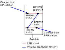
In this way, if the RPR ringlet on Switch A fails (Line 1 or Line 2 in Figure 5-2), Switch A automatically detects the fault and turns down the RPR logical interfaces RPRPOS 3/1/1 and RPRPOS 5/1/1.
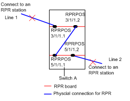
Figure 5-2 Distributed RPR (in case of ringlet error)
5.2 Distributed RPR Configuration
![]() Caution:
Caution:
l Distributed RPR doest not support Layer 2 tunneling or its expanded functions, RPR intersecting rings, or VRRP over RPR.
l Do not execute the loopback internal command on the distributed RPR logical interfaces. This command may cause errors to distributed RPR.
Follow these steps to configure distributed RPR:
|
To do… |
Use the command… |
Remarks |
|
Enter system view |
system-view |
— |
|
Create an aggregation group manually for distributed RPR |
link-aggregation group agg-id mode manual |
Required |
|
Enter RPR logical interface view |
interface { RprPos | Rpr10GE | RprGE } interface-number |
— |
|
Add the RPR logical interface to the specified manual aggregation group |
port link-aggregation group agg-id |
Required |
|
Quit to system view |
quit |
— |
|
Enter RPR physical port view |
interface { RprPos | Rpr10GE | RprGE } interface-number |
— |
|
Configure RPR physical ports as mate port |
port-mode mate |
Optional Disabled by default. |
|
Display information about aggregation group of distributed RPR |
display rpr link-aggregation |
This command can be executed in any view. |
|
Enable debugging for distributed RPR |
debugging rpr backup { debug | error | event } |
Disabled by default. |
5.3 Configuration Example
I. Network requirements
l H3C A, H3C B, H3C C, and H3C D form an RPR.
l Configure distributed RPR on H3C A. The RPR logical interfaces of the two RPR boards are RPRPOS 3/1/1 and RPRPOS 5/1/1. Connect the mate ports RPRPOS 3/1/1.2 and RPRPOS 5/1/1.1.
II. Network diagram
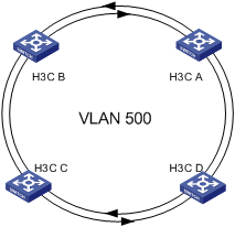
Figure 5-3 Network diagram for distributed RPR
III. Configuration procedure
& Note:
Only distributed RPR-related configurations are listed.
<H3C> system-view
[H3C] link-aggregation group 1 mode manual
[H3C] interface RprPos3/1/1
[H3C-RprPos3/1/1] port link-aggregation group 1
[H3C-RprPos3/1/1] quit
[H3C] interface RprPos5/1/1
[H3C-RprPos5/1/1] port link-aggregation group 1
[H3C-RprPos5/1/1] interface RprPos3/1/1.2
[H3C-RprPos3/1/1.2] port-mode mate
[H3C-RprPos3/1/1.2] interface RprPos5/1/1.1
[H3C-RprPos5/1/1.1] port-mode mate