- Table of Contents
-
- H3C S9500 Operation Manual-Release1648[v1.24]-01 Access Volume
- 00-1Cover
- 01-Ethernet Port Configuration
- 02-POS Port Configuration
- 03-Link Aggregation Configuration
- 04-Port Isolation Configuration
- 05-VLAN Configuration
- 06-MAC Address Table Management Configuration
- 07-GVRP Configuration
- 08-QinQ Configuration
- 09-Ethernet Port Loopback Detection Configuration
- 10-DLDP Configuration
- 11-Ethernet OAM Configuration
- 12-Smart Link and Monitor Link Configuration
- 13-MSTP Configuration
- 14-BPDU Tunnel Configuration
- 15-HVRP Configuration
- 16-RRPP Configuration
- 17-RPR Configuration
- Related Documents
-
| Title | Size | Download |
|---|---|---|
| 15-HVRP Configuration | 212.58 KB |
Table of Contents
1.1.3 Operating Mechanism of HVRP
1.1.4 Network Topologies Supported by HVRP
1.2.2 Configuring HVRP Time Parameters and Attributes
1.2.3 Configuring VLAN Attributes of HVRP
1.3 Displaying and Maintaining HVRP Configuration
1.4 HVRP Configuration Example
Chapter 1 HVRP Configuration
When configuring HVRP, go to these sections for information you are interested in:
l Displaying and Maintaining HVRP Configuration
1.1 Introduction to HVRP
1.1.1 Background
Currently, metropolitan area networks (MANs) established by carriers usually adopt a ring topology or a tree topology. Whichever topology is in use, it is always necessary that devices on the distribution layer support the learning of a large number of MAC addresses in order to satisfy the network access needs of all connected users. With the continuous increase of network users, the current number of MAC addresses that a switch can learn may no longer meet the actual demands. This means that MAC addresses of some users cannot be learnt by the switch, resulting in packets being broadcast within the VLAN, taking up extra bandwidth and undermining network functionality.
To address the issue, the Hierarchy VLAN Register Protocol (HVRP) was introduced.
HVRP enables dynamic registration and aging of VLANs for a given port in certain networking environments by differentiating user VLANs (local VLANs) from non-user VLANs. It thus saves the amount of space needed for storing MAC addresses, increasing the user capacity of the whole device.
1.1.2 Basic Concepts of HVRP
I. HVRP
In certain network environments, HVRP can be used to save MAC address storage space for switches, and therefore, improve network scalability.
II. HVRP ports
Ports with HVRP configured, that is, ports that can send and receive HVRP packets.
III. Root HVRP port
A port with HVRP configured, also configured as a root port on a spanning tree.
IV. Designated HVRP ports
A port with HVRP configured, also configured as a designated port on a spanning tree.
V. Local VLANs
Local VLANs are the VLANs to which the ports with HVRP disabled belong.
VI. Registration of VLAN
Add VLANs that meet certain criteria to the list of VLANs interconnecting a given HVRP port.
VII. Aging of VLAN
Delete a specified VLAN from the list of VLANs interconnecting a given HVRP port.
VIII. Permanent VLAN
Permanent VLANs are VLANs that will never be aged out by HVRP-enabled ports after being created.
IX. Sending local VLAN
An HVRP packet contains the local VLAN information. With STP enabled, the HVRP-enabled root port is responsible for sending HVRP packets.
X. VLAN registration timer
VLAN registration timer determines the interval for a root port to send HVRP registered VLAN packets.
XI. VLAN registration ageing timer
If a port does not receive a specific HVRP VLAN registration packet within the registered-VLAN aging time, the corresponding VLAN will be aged out.
1.1.3 Operating Mechanism of HVRP
By means of dynamic VLAN registration and aging, HVRP ages VLANs that no longer participate in packet forwarding and only keeps those needed. When there are no more than two ports left in a VLAN, no MAC address will be learnt and data packets will be broadcast within the VLAN, which does not affect the network bandwidth.
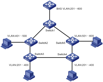
Figure 1-1 shows an illustrative example of HVRP mechanism.
l Enable STP throughout the network.
l Connect the switches through trunk ports with HVRP enabled. They carry the same set of VLANs, VLAN 201 through VLAN 600 in this example.
l Disable HVRP on the ports that do not belong to an STP ring.
1) VLAN Registration
l Each device sends out its local VLAN information periodically through the HVRP root port.
l Each device forwards the received local VLAN information through its root port, and in the meantime registers the local VLAN information received through the designated port on the receiving port.
l The root bridge only registers received local VLANs with the ports that have received HVRP packets.
l VLAN registration can be carried out only on HVRP designated ports.
l Only VLANs that have been statically configured on a given port can be registered with that port. For example, VLAN 999 cannot be registered with a port that does not belong to it even if the port has received the local VLAN information that contains VLAN 999.
l Registration of a VLAN can affect its aging.
2) Aging of VLAN
If the HVRP designated port does not receive any VLAN registration information within the VLAN aging time, the corresponding VLANs on the port will be aged out.
3) Sending and maintenance of local VLAN information
When a local VLAN change takes place (for instance, invalidation of a local VLAN due to configuration change), the switch sends the local VLAN information immediately through the HVRP root port.
In addition, the HVRP root port sends local VLAN registration packets periodically.
4) Actions taken when an HVRP-enabled port goes up or down
When an HVRP-enabled port is brought up or shut down, packets may be forwarded improperly in the network because some VLANs are aged. Therefore, upon detecting HVRP-enabled port state changes (port up or down events), the system sends restore packets to have all the switches in the network reregister the aged VLANs on their previous ports.
5) Actions upon STP port role change
When the STP role of an HVRP port has changed, the aged VLANs for this given port should be immediately reregistered with this port.
6) Counting of ports within a given VLAN
l The number of ports for a given VLAN should be updated whenever the following events occurred: a new port is added to the VLAN, a port has left the VLAN, a VLAN is registered, and the VLAN has aged.
l An aggregation port is treated as a single port.
7) MAC address learning in a given VLAN
l Learn MAC addresses when more than two non-aged ports are present in the VLAN.
l Pause MAC address learning and remove dynamic MAC address entries that have been learnt when only two or less than two non-aged ports are present in the VLAN.
1.1.4 Network Topologies Supported by HVRP
I. Single Ring Networks
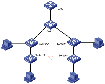
Figure 1-2 An HVRP-supported single ring network
Features of single ring networks:
l STP is enabled network wide.
l Switch 1, Switch 2, Switch 3, Switch 4, and Switch 5 are all Layer 2 switches. Switch 1 is the root bridge and the rest connect to layer 3 devices via Switch 1.
l The link between Switch 3 and Switch 4 is blocked by STP.
l The clients illustrated in Figure 1-2 include all clients connected with the device, including terminal clients and DSLAM clients.
l In practice, Switch 1 can be either a Layer 2 or a Layer 3 device.
II. Multi-Ring Networks
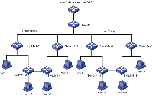
Figure 1-3 An HVRP-supported multi-ring network
Features of multi-ring networks:
l MSTP is enabled network wide, with each ring corresponding to an MSTP instance. All the devices belong to the same domain.
l Switch 1-2, Switch 1-3, Switch 1-4, Switch 1-5, Switch N-2, Switch N-3, Switch N-4, and Switch N-5 are all Layer 2 switches. Switch 1 is the root bridge of all instances and the other devices connect to Layer 3 devices via Switch 1 (Switch 1 can be either a Layer 2 or a Layer 3 device).
1.2 HVRP Configuration Task
Complete the following tasks to configure HVRP:
l Configuring HVRP Time Parameters and Attributes
l Configuring VLAN Attributes of HVRP
1.2.1 Configuring HVRP
HVRP can be enabled in system view or in Ethernet port view. When HVRP is disabled globally in system view or disabled in Ethernet port view, all the other HVRP-dependent configurations will be disabled as a result.
I. Configuration Prerequisites
l HVRP-enabled ports must be Trunk ports.
l STP is enabled globally.
l GVRP is disabled globally.
II. Configuring HVRP
Follow these steps to configure HVRP in system view:
|
Use the command … |
Remarks |
|
|
Enter system view |
system-view |
— |
|
Enable HVRP |
hvrp enable |
Required By default, HVRP is disabled globally. |
Follow these steps to configure HVRP in port view:
|
To do … |
Use the command … |
Remarks |
|
Enter system view |
system-view |
— |
|
Enter Ethernet port view |
interface interface-type interface-num |
— |
|
Enable HVRP |
hvrp enable |
Required By default, HVRP is disabled. |
![]() Caution:
Caution:
l HVRP enabled ports must be Trunk ports.
l Before enabling HVRP on a port, it is recommended to remove VLAN 1 from the port.
l You can enable HVRP for an Ethernet port only after enabling HVRP globally.
l Disabling HVRP globally will disable HVRP for all ports.
l After you enable HVRP, do not use the mac-address max-count command on a VLAN.
l HVRP configuration cannot be copied between ports.
l HVRP and GVRP are mutually exclusive.
l XP4 boards (except XP4L boards) do not support HVRP.
1.2.2 Configuring HVRP Time Parameters and Attributes
The parameter and attribute configuration tasks include:
l Configuring the VLAN registration timer
l Configuring the registered-VLAN aging interval
I. Configuration Prerequisites
The following conditions must be met:
l HVRP is enabled globally.
l HVRP is enabled on a specified port.
II. Configuring Time Parameters and Attributes
Follow these steps to configure time parameters and attributes:
|
To do … |
Use the command … |
Remarks |
|
Enter system view |
system-view |
— |
|
Configure the VLAN registration timer |
hvrp timer registervlan timer-num |
Optional It is 5 seconds by default. |
|
Configure the registered-VLAN aging interval |
hvrp timer registervlan-age timer-num |
Optional It is 15 seconds by default. |
![]() Caution:
Caution:
l The VLAN registration timer must be smaller than the registered-VLAN aging interval. It is recommended that the latter be at least three times the former.
l On a ring topology, all devices must have the same VLAN registration timer.
1.2.3 Configuring VLAN Attributes of HVRP
The VLAN attribute configuration tasks for HVRP include:
l Configuring a permanent VLAN
l Configuring the system to age all the VLANs
VLANs on a HVRP-enabled designated port can be aged out, while permanent VLANs will never be aged out. Make sure all the specified VLANs are created before performing the configurations below.
I. Configuring a permanent VLAN
The VLAN(s) on an HVRP port may be aged out while a permanent VLAN will never be aged out.
You cannot configure a VLAN as a permanent VLAN unless the VLAN has been created.
Follow these steps to configure a permanent VLAN:
|
To do… |
Use the command … |
Remarks |
|
Enter system view |
system-view |
— |
|
Configure permanent VLANs |
hvrp permanent-vlan vlan-id [ to vlan-id ] |
Optional By default, no permanent VLAN exists. |
![]() Caution:
Caution:
You are recommended to configure a VLAN with an IP address as a permanent VLAN.
II. Configuring the system to age all the VLANs
In a single-ring network or multi-ring network, you can configure the system to age all VLANs or only local VLANs. The default configuration is recommended. You can use the hvrp vlan-age all command to configure the system to age all the VLANs.
A switch located on the intersection point of the intersected rings must be configured to age all the VLANs.
Follow these steps to configure the system to age all the VLANs:
|
To do … |
Use the command … |
Remarks |
|
Enter system view |
system-view |
— |
|
Configure the system to age all the VLANs |
hvrp vlan-age all |
Optional |
1.3 Displaying and Maintaining HVRP Configuration
|
To do … |
Use the command … |
Remarks |
|
Display brief HVRP information |
display hvrp brief |
Available in any view |
|
Display detailed information on HVRP |
display hvrp verbose |
Available in any view |
|
Display local VLAN information |
display hvrp local-vlan |
Available in any view |
|
Display information on VLANs that are actually allowed to pass through the ports |
display hvrp port-vlan |
Available in any view |
|
Enable HVRP error debugging |
debugging hvrp error |
Available in user view |
|
Enable VLAN debugging of HVRP |
debugging hvrp info |
Available in user view |
1.4 HVRP Configuration Example
I. Network requirements
l The topology is a single ring network.
l STP is enabled network wide, with Switch 1 as the root bridge.
l Switch 1, Switch 2, Switch 3, Switch 4, and Switch 5 are all Layer 2 switches. Switch 1 is the root bridge and the rest switches connect with Layer 3 devices via Switch 1.
l The link between Switch 3 and Switch 4 is blocked by STP.
l User 1 and user 4 are household users who only want to visit the Internet through Switch 1; user 2 and user 3 are enterprise users, and therefore in addition to visiting the Internet, they also want to visit each other.
l Users refer to all users connected with the switches, including terminal users and DSLAM users.
II. Network diagram
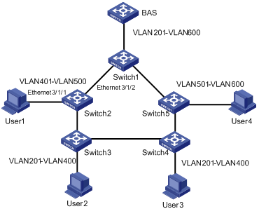
Figure 1-4 HVRP Network diagram
III. Configuration procedure
# Create VLAN 201 to VLAN 600 on switches 1 through 5. Ports with user devices attached are configured to enable the corresponding VLANs to pass through them. For instance, Ethernet 3/1/1 on Switch 2 that connects with user 1 can be configured as follows:
<H3C> system-view
System View: return to User View with Ctrl+Z.
[H3C] interface Ethernet 3/1/1
[H3C-Ethernet3/1/1] port link-type trunk
[H3C-Ethernet3/1/1] port trunk permit vlan 401 to 500
# Enable STP globally.
[H3C-Ethernet3/1/1] quit
[H3C] stp enable
# Enable HVRP globally.
[H3C] hvrp enable
# Configure Ethernet 3/1/2 in the ring network to be a trunk port, and configure the port to permit the corresponding VLANs to pass through.
<H3C> system-view
System View: return to User View with Ctrl+Z.
[H3C] interface Ethernet 3/1/2
[H3C-Ethernet3/1/2] port link-type trunk
[H3C-Ethernet3/1/2] port trunk permit vlan 200 to 600
# Enable HVRP for Ethernet 3/1/2.
[H3C-Ethernet3/1/2] hvrp enable
The configuration of any other port in the STP ring is similar to that of Ethernet 3/1/2, and the configuration of a port directly connecting to a user is similar to that of Ethernet 3/1/1. So their configuration procedures are omitted here.