- Table of Contents
-
- H3C S9500 Operation Manual-Release1648[v1.24]-01 Access Volume
- 00-1Cover
- 01-Ethernet Port Configuration
- 02-POS Port Configuration
- 03-Link Aggregation Configuration
- 04-Port Isolation Configuration
- 05-VLAN Configuration
- 06-MAC Address Table Management Configuration
- 07-GVRP Configuration
- 08-QinQ Configuration
- 09-Ethernet Port Loopback Detection Configuration
- 10-DLDP Configuration
- 11-Ethernet OAM Configuration
- 12-Smart Link and Monitor Link Configuration
- 13-MSTP Configuration
- 14-BPDU Tunnel Configuration
- 15-HVRP Configuration
- 16-RRPP Configuration
- 17-RPR Configuration
- Related Documents
-
| Title | Size | Download |
|---|---|---|
| 08-QinQ Configuration | 184.63 KB |
1.1.3 Adjusting TPID Values of QinQ Packets
1.2 Configuring VLAN VPN on a Port
1.2.1 Configuration Prerequisites
1.3 Configuring Traffic Classification-Based Nested VLAN
1.3.1 Configuration Prerequisites
1.4 Configuring the TPID to Be Used in the Outer Tag
1.4.1 Configuration Prerequisites
1.5 Configuring VLAN-VPN Tunneling
1.5.1 Introduction to VLAN-VPN Tunneling
1.5.2 Configuring VLAN-VPN tunneling
1.6 Displaying and Maintaining QinQ Configuration
1.7 QinQ Configuration Examples
1.7.1 Traffic Classification-Based Nested VLAN Configuration Example
1.7.2 TPID Value Configuration Example
1.7.3 VLAN-VPN Tunneling Configuration Example
Chapter 1 QinQ Configuration
When configuring QinQ, go to these sections for the information you are interested in:
l Configuring VLAN VPN on a Port
l Configuring Traffic Classification-Based Nested VLAN
l Configuring the TPID to Be Used in the Outer Tag
l Configuring VLAN-VPN Tunneling
l Displaying and Maintaining QinQ Configuration
1.1 QinQ Overview
1.1.1 Introduction to QinQ
QinQ is a technique that enables packets to be transmitted across the operators’ backbone networks with VLAN tags of private networks nested in those of public networks. In public networks, packets of this type are transmitted by their outer VLAN tags (that is, the VLAN tags of public networks). And those of private networks, which are nested in the VLAN tags of public networks, remain intact.
Figure 1-1 shows the structure of a single-tagged frame and a double-tagged frame.
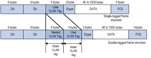
Figure 1-1 Single-tagged frame structure vs. double-tagged Ethernet frame structure
Compared with MPLS-based L2VPN, QinQ has the following features:
l Layer 2 VPN tunnels that are simpler.
l QinQ can be implemented without the support of signaling protocols. You can enable QinQ by static configuring.
As QinQ is implemented through trunk port defined in 802.1Q, all devices along tunnels with QinQ employed must be 802.1Q-enabled. Therefore, QinQ is suitable for small-sized metropolitan area networks (MANs) or intranets with Layer 3 switches operate as the core layer devices.
QinQ provides you with the following benefits:
l Saves public network VLAN IDs.
l You can have VLAN IDs of your own, which do not conflict with public network VLAN IDs.
l Provide simple Layer 2 VPN solutions for small-sized MANs or intranets.
1.1.2 Implementation of QinQ
QinQ can be implemented on S9500 series switches in the following ways:
1) Enabling VLAN VPN on ports
With VLAN VPN enabled, a received packet is tagged with the default VLAN tag of the port no matter whether or not the packet carries a VLAN tag. Otherwise, the packet is transmitted with the default VLAN tag carried.
2) Configuring traffic classification-based nested VLANs
Traffic classification-based nested VLANs is also called flexible QinQ. It is a kind of QinQ implemented in a more flexible way. You can specify to perform the following operations on packets that match specified ACL rules:
l Setting the outer VLAN tags
l Modifying the outer VLAN tags
1.1.3 Adjusting TPID Values of QinQ Packets
Tag protocol identifier (TPID) is a portion of the VLAN tag field. IEEE 802.1Q specifies the value of TPID to be 0x8100.
The structure of the Tag field of an Ethernet frame defined by IEEE 802.1Q is as follows:
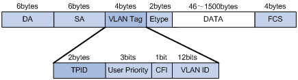
Figure 1-2 The structure of the VLAN Tag field of an Ethernet frame
By default, a S9500 series switch uses 0x8100 as the value of the TPID field, which is defined by IEEE 802.1Q. But S9500 series switches can also adjust the TPID values of QinQ packets. This ensures S9500 series switches are compatible with devices coming from other vendors even through the later use other TPID values (such as 0x9100 or 0x9200) in the outer tags of QinQ packets.
To modify the TPID values of packets, you need to set the ports connecting to the public networks to be VLAN-VPN uplink ports, whose TPID value can be configured by users. After you configure a TPID value for a VLAN-VPN uplink port, the switch substitutes the new TPID values for those VLAN-VPN uplink ports in the outer tags carried by received packets before transmitting the packet through the VLAN-VPN uplink ports to enable these packets to be accepted by devices of other vendors.
1.2 Configuring VLAN VPN on a Port
1.2.1 Configuration Prerequisites
l GARP VLAN registration protocol (GVRP), spanning tree protocol (STP), and 802.1x protocol are disabled on the port.
l IGMP Snooping is disabled in the VLAN to which the port belongs.
l IGMP is disabled in the VLAN to which the port belongs.
1.2.2 Configuration Procedure
Table 1-1 Configure VLAN VPN on a port
|
Operation |
Command |
Remarks |
|
Enter system view |
system-view |
— |
|
Enter Ethernet port view |
interface { interface-type interface-number | interface-name } |
— |
|
Enable VLAN VPN |
vlan-vpn enable |
By default, VLAN VPN is disabled on a port. |
|
Display VLAN VPN configuration information about all ports in the system |
display port vlan-vpn |
Information about the current TPID value, VLAN-VPN ports, VLAN-VPN uplink ports is displayed. |
![]() Caution:
Caution:
l VLAN VPN is unavailable to ports on which GVRP, STP, NTP, 802.1x, or RRPP is enabled.
l VLAN VPN cannot be enabled on a port if the VLAN which the port belongs to has IGMP Snooping enabled or its VLAN interface has IGMP enabled. Similarly, if a port is VLAN VPN-enabled, you cannot enable IGMP Snooping in the VLAN to which the port belongs or enable IGMP on the VLAN interface of the VLAN.
l If you have enabled VLAN VPN for the ports in the VLAN, the VLAN cannot be removed.
l After you enable the QinQ function, the configured ACL may fail to function.
1.3 Configuring Traffic Classification-Based Nested VLAN
1.3.1 Configuration Prerequisites
l ACLs and corresponding rules to be applied already exist.
l The VLANs to be specified by the nested-vlanid argument already exist.
1.3.2 Configuration Procedure
Table 1-2 Configure traffic classification-based nest vlan
|
Operation |
Command |
Remarks |
|
|
Enter system view |
system-view |
— |
|
|
Enter Ethernet port view or port group view |
interface { interface-type interface-number | interface-name } or port-group index |
— |
|
|
Set outer VLAN tags for the packets matching the ACL rules |
Deliver a Layer 3 traffic classification rule |
traffic-redirect inbound ip-group { acl-number | acl-name } [ rule rule [ system-index index ] ] nested-vlan nested-vlanid [ interface interface-type interface-number destination-vlan l2-vpn ] | link-aggregation group groupid destination-vlan | smart-link group groupid destination-vlan ] |
Make sure the Nested-VLAN already exists to prevent otherwise the packets from being discarded. |
|
Deliver both Layer 2 and Layer 3 traffic classification rules |
traffic-redirect inbound ip-group { acl-number | acl-name } [ rule rule ] link-group { acl-number | acl-name } [ rule rule ] nested-vlan nested-vlanid [ interface interface-type interface-number destination-vlan l2-vpn ] | link-aggregation group groupid destination-vlan | smart-link group groupid destination-vlan ], or, traffic-redirect inbound ip-group { acl-number | acl-name } link-group { acl-number | acl-name } rule rule nested-vlan nested-vlanid [ interface interface-type interface-number destination-vlan [ l2-vpn ] | link-aggregation group groupid destination-vlan | smart-link group groupid destination-vlan ] |
||
|
Deliver a Layer 2 traffic classification rule |
traffic-redirect inbound link-group { acl-number | acl-name } [ rule rule [ system-index index ] ] nested-vlan nested-vlanid [ interface interface-type interface-number } destination-vlan l2-vpn ] | link-aggregation group groupid destination-vlan | smart-link group groupid destination-vlan ] |
||
|
Modify outer VLAN tags for the packets matching the ACL flow rules |
Deliver a Layer 3 traffic classification rule |
traffic-redirect inbound ip-group { acl-number | acl-name } [ rule rule [ system-index index ] ] modified-vlan modified-vlanid |
This command modifies the outer VLAN tag of the packets. |
|
Deliver both Layer 2 and Layer 3 traffic classification rules |
traffic-redirect inbound ip-group { acl-number | acl-name } [ rule rule ] link-group { acl-number | acl-name } [ rule rule ] modified-vlan modified-vlanid, or, traffic-redirect inbound ip-group { acl-number | acl-name } link-group { acl-number | acl-name } rule rule modified-vlan modified-vlanid |
||
|
Deliver a Layer 2 traffic classification rule |
traffic-redirect inbound link-group { acl-number | acl-name } [ rule rule [ system-index index ] ] modified-vlan modified-vlanid |
||
![]() Caution:
Caution:
At present, the traffic-redirect { nested-vlan | modified-vlan } command is only supported on boards with a suffix of DB or DC.
1.4 Configuring the TPID to Be Used in the Outer Tag
1.4.1 Configuration Prerequisites
As VLAN-VPN uplink ports typically works with the VLAN VPN ports, make sure that VLAN VPN is disabled on the port before proceeding with the following configuration.
1.4.2 Configuration Procedure
Table 1-3 Configure the TPID to be used in the outer tag
|
Operation |
Command |
Remarks |
|
Enter system view |
system-view |
— |
|
Configure the TPID value |
vlan-vpn tpid value |
The value argument ranges from 1 to 0xFFFF and defaults to 0x8100. Do not set the TPID value to a value that may cause a conflict, such as that of known protocol type. The TPID value can be modified only on VLAN-VPN uplink egress ports. |
|
Enter Ethernet port view |
interface { interface-type interface-number | interface-name } |
— |
|
Set the port to be a VLAN-VPN uplink port. |
vlan-vpn uplink enable |
By default, a port is not a VLAN-VPN uplink port. |
|
Display VLAN VPN configuration information about all ports in the system |
display port vlan-vpn |
Information about the current TPID value, VLAN-VPN ports and VLAN-VPN uplink ports is display. |
![]() Caution:
Caution:
l At present, LSB1XP4 and LSB1TGX1 cards do not support this configuration.
l The vlan-vpn uplink enable and the vlan-vpn enable command are mutual exclusive. That is, you cannot used the vlan-vpn enable command while on a port the vlan-vpn uplink enable command is in effect on the same port, and vice versa.
1.5 Configuring VLAN-VPN Tunneling
1.5.1 Introduction to VLAN-VPN Tunneling
VLAN-VPN tunneling enables customer networks in different geographic regions to transmit BPDU packets to each other transparently through the designated VLAN VPN over the service provider network.
As shown in Figure 1-3, the service provider network comprises packet input and output devices. The customer networks include network A and network B. Through the configuration on the devices at both ends of the service provider network, the destination MAC address of the BPDU packet is replaced with a MAC address in a special format at one end, and the MAC address is converted back to the original destination MAC address at the other end. In this way the packet is transmitted transparently over the service provider network.
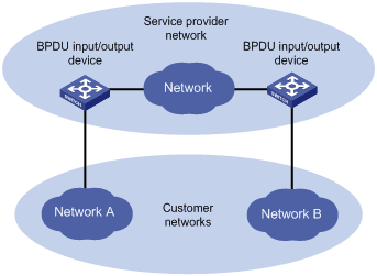
Figure 1-3 VLAN-VPN tunneling network hierarchy
1.5.2 Configuring VLAN-VPN tunneling
Perform the following configuration to configure VLAN-VPN tunneling.
Table 1-4 Configure VLAN-VPN tunneling
|
Operation |
Command |
Remarks |
|
Enter system view |
system-view |
— |
|
Enable VLAN-VPN tunneling |
vlan-vpn tunnel |
Required |
|
Enter Ethernet port view |
interface interface-type interface-number |
— |
|
Enable VLAN VPN of the port |
vlan-vpn enable |
Required By default, VLAN VPN is disabled on a port. |
1.6 Displaying and Maintaining QinQ Configuration
|
To do … |
Use the command … |
Remarks |
|
Display the configuration information of VLAN VPN-enabled PVCs of an ATM primary interface or subinterface. |
display atm vlan-vpn [ interface atm interface-number [ pvc { pvc-name | vpi/vci } ] ] |
Available in any view |
|
Display VLAN VPN-related configuration information in the system |
display port vlan-vpn |
Available in any view |
|
Monitor packets of specified users in the inbound direction of a specified interface. |
traceuser interface interface-type interface-number [ mac mac-address ] [ vlan vlan-id ] [ number number ] |
Available in any view |
1.7 QinQ Configuration Examples
1.7.1 Traffic Classification-Based Nested VLAN Configuration Example
I. Network requirements
l As shown in Figure 1-4, two types of services run on the S9512 switch: common internet access and on-demand multicast video. Traffic classification-based nested VLAN encapsulates different tags at the exterior layer to distinguish the two services based on the packet tag sent by the digital subscriber line access multiplexer (DSLAM).
l VLAN 100 to VLAN 512 comprise home users that have access to the Internet. For the packets in this VLAN range, S9512 needs to encapsulate another external tag of VLAN 1000, and then sends the packets to BRAS.
l VLAN 600 is a multicast VLAN. When receiving a packet with the tag of VLAN 600, S9512 does not process the packet.
II. Network diagram
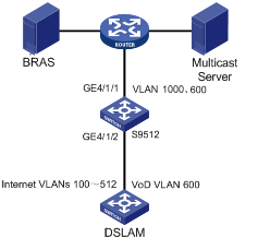
Figure 1-4 Network diagram for traffic classification-based nested VLAN configuration
III. Configuration procedure
# Enable IGMP-snooping in VLAN 600.
<H3C> system-view
[H3C] vlan 600
[H3C-vlan600] igmp-snooping enable
[H3C-vlan600] quit
# Configure the downlink port GigabitEthernet 4/1/2 to be a hybrid port. Configure VLAN 1000 to be untagged and VLAN 600 to be tagged.
[H3C] interface GigabitEthernet4/1/2
[H3C-GigabitEthernet4/1/2] port link-type hybrid
[H3C-GigabitEthernet4/1/2] port hybrid vlan 600 tagged
[H3C-GigabitEthernet4/1/2] port hybrid vlan 1000 untagged
[H3C-GigabitEthernet4/1/2] quit
# Configure a flow template.
[H3C] flow-template user-defined slot 4 s-tag-vlan
[H3C-GigabitEthernet4/1/2] flow-template user-defined
[H3C-GigabitEthernet4/1/2] quit
# Configure QinQ so that when the packets of VLAN 100 to 512 leave the uplink port GigabitEthernet 4/1/1, they need to be tagged with the exterior tag of VLAN 100.
[H3C] acl number 4000
[H3C-acl-link-4000] rule 0 permit s-tag-vlan 100 to 512
[H3C-GigabitEthernet4/1/2] traffic-redirect inbound link-group 4000 rule 0 nested-vlan 1000
[H3C-GigabitEthernet4/1/2] vlan filter disable
[H3C-GigabitEthernet4/1/2] quit
# Configure the uplink port GigabitEthernet 4/1/1 to a trunk port and allow the packets of VLAN 1000 and VLAN 600 to pass the uplink port.
[H3C] interface GigabitEthernet4/1/1
[H3C-GigabitEthernet4/1/1] port link-type trunk
[H3C-GigabitEthernet4/1/1] port trunk permit vlan 600 1000
1.7.2 TPID Value Configuration Example
I. Network requirements
l Switch A and Switch C are S9500 series switches. Switch B is a switch produced by other vendor. It uses TPID value of 0x9100.
l Two networks are connected to the GigabitEthernet 2/1/1 ports of Switch A and Switch C respectively.
l Switch B only permits packets of VLAN 10.
l It is required that packets of VLANs other than VLAN 10 can be exchanged between the networks connected to Switch A and Switch C.
II. Network diagram
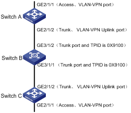
Figure 1-5 Network diagram for adjusting TPID values
III. Configuration Procedure
1) Configure Switch A and Switch C. As the configuration performed on Switch A and Switch C is the same, configuration on Switch C is omitted.
# Set the TPID value of the VLAN-VPN uplink port to 0x9100.
<SwitchA>system-view
System View: return to User View with Ctrl+Z.
[SwitchA]vlan-vpn tpid 9100
[SwitchA]vlan 10
[SwitchA-vlan10]quit
# Configure the GigabitEthernet 2/1/2 port to be a VLAN-VPN uplink port and add it to VLAN 10 (a trunk port).
[SwitchA]interface GigabitEthernet2/1/2
[SwitchA-GigabitEthernet2/1/2]port link-type trunk
[SwitchA-GigabitEthernet2/1/2]port trunk permit vlan 10
[SwitchA-GigabitEthernet2/1/2]vlan-vpn uplink enable
# Configure the GigabitEthernet 2/1/1 port to be a VLAN VPN port and add it to VLAN 10 (an access port).
[SwitchA]interface GigabitEthernet2/1/1
[SwitchA-GigabitEthernet2/1/1]port access vlan 10
[SwitchA-GigabitEthernet2/1/1]vlan-vpn enable
[SwitchA-GigabitEthernet2/1/1]quit
2) Configure Switch B
Because Switch B is produced by other vendor, related commands may differ from those available to S9500 switches. So only the operation is listed, as shown below:
l Configure GigabitEthernet 3/1/1 and GigabitEthernet 3/1/3 ports of Switch B to be trunk ports.
l Add the two ports to VLAN 10.
& Note:
The following describes how a packet is forwarded from Switch A to Switch C.
l As the GigabitEthernet 2/1/1 port of Switch A is a VLAN VPN port, when a packet reaches GigabitEthernet 2/1/1 port of Switch A, it is tagged with the default VLAN tag (VLAN 10, the outer tag) and is then forwarded to GigabitEthernet 2/1/2 port.
l Because GigabitEthernet 2/1/2 port is a VLAN-VPN uplink port with a TPID of 0x9100, Switch A changes the TPID value in the outer VLAN Tag of the packet to 0x9100, and forwards the packet to the public network.
l The packet reaches GigabitEthernet 3/1/2 port of Switch B. Switch B sends the packet to its GigabitEthernet 3/1/1 port by forwarding the packet in VLAN 10.
l The packet is forward from GigabitEthernet 3/1/1 port of Switch B to the network on the other side and enters GigabitEthernet 2/1/2 port of Switch C, Switch C sends the packet to its GigabitEthernet 2/1/1 port by forwarding the packet in VLAN 10. As GigabitEthernet 2/1/1 port is an access port, Switch C strip off the outer VLAN tag of the packet and restores the original packet.
A packet goes through similar procedure when traveling from Switch C to Switch A.
IV. Verification
The configuration is successful if packets sourced from the networks connected to Switch A can reach those connected to Switch C, or packets sourced from the networks connected to Switch C can reach those connected to Switch A.
1.7.3 VLAN-VPN Tunneling Configuration Example
I. Network requirements
l S9500 series switches, namely Switch C and D in the network diagram, serve as devices used to access the service provider network.
l S2000 series switches, namely Switch C and D in the network diagram, serve as devices used to access the customer network.
l Interconnect switch C and switch D through trunk ports. Enable VLAN-VPN tunneling to transmit packets transparently between the customer network and the service provider network.
II. Network diagram
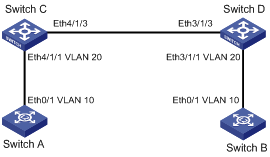
Figure 1-6 Configure VLAN-VPN tunneling
III. Configuration procedure
1) Configure switch A.
# Enable MSTP.
<H3C> system-view
[H3C] stp enable
# Set the port to a trunk port and allow the packets of VLAN 10 to pass the port.
[H3C] vlan 10
[H3C-Ethernet0/1] port link-type trunk
[H3C-Ethernet0/1] port trunk permit vlan 10
2) Configure switch B.
# Enable MSTP.
<H3C> system-view
[H3C] stp enable
# Set the port to a trunk port and allow the packets of VLAN 10 to pass the port.
[H3C] vlan 10
[H3C-Ethernet0/1] port link-type trunk
[H3C-Ethernet0/1]port trunk permit vlan 10
3) Configure switch C.
# Enable MSTP.
<H3C> system-view
[H3C] stp enable
# Enable VLAN-VPN tunneling.
[H3C] vlan-vpn tunnel
# Add Ethernet 4/1/1 to VLAN 20.
[H3C] vlan 20
[H3C-Vlan20] port Ethernet4/1/1
[H3C-Vlan20] quit
# Disable STP and enable VLAN-VPN on Ethernet 4/1/1.
[H3C] interface Ethernet4/1/1
[H3C-Ethernet4/1/1] stp disable
[H3C-Ethernet4/1/1] vlan-vpn enable
[H3C-Ethernet4/1/1] quit
# Set Ethernet 4/1/3 to a trunk port and add this port to all the VLANs.
[H3C] interface Ethernet4/1/3
[H3C-Ethernet4/1/3] port link-type trunk
[H3C-Ethernet4/1/3] port trunk permit vlan all
4) Configure switch D.
# Enable MSTP.
<H3C> system-view
[H3C] stp enable
# Enable VLAN-VPN tunneling.
[H3C] vlan-vpn tunnel
# Add Ethernet 3/1/1 to VLAN 20.
[H3C] vlan 20
[H3C-Vlan20] port Ethernet3/1/1
[H3C-Vlan20] quit
# Disable STP and enable VLAN-VPN on Ethernet 3/1/1.
[H3C] interface Ethernet3/1/1
[H3C-Ethernet3/1/1] stp disable
[H3C-Ethernet3/1/1] vlan-vpn enable
[H3C-Ethernet3/1/1] quit
# Set Ethernet 3/1/3 to a trunk port and add this port to all the VLANs.
[H3C] interface Ethernet3/1/3
[H3C-Ethernet3/1/3] port link-type trunk
[H3C-Ethernet3/1/3] port trunk permit vlan all
![]() Caution:
Caution:
l STP must be enabled on VLAN-VPN tunneling-enabled devices; otherwise BPDUs in the customer network cannot be transmitted transparently.
l VLAN-VPN-enabled ports must be configured to Access ports. The link type of the intermediate service provider network must be configured to the Trunk link.
l VLAN-VPN tunneling is unavailable to ports with any of the protocols among 802.1x, GVRP, STP, network topology discovery protocol (NTDP), and GARP multicast registration protocol (GMRP) enabled.