- Table of Contents
-
- H3C S9500 Operation Manual-Release1648[v1.24]-01 Access Volume
- 00-1Cover
- 01-Ethernet Port Configuration
- 02-POS Port Configuration
- 03-Link Aggregation Configuration
- 04-Port Isolation Configuration
- 05-VLAN Configuration
- 06-MAC Address Table Management Configuration
- 07-GVRP Configuration
- 08-QinQ Configuration
- 09-Ethernet Port Loopback Detection Configuration
- 10-DLDP Configuration
- 11-Ethernet OAM Configuration
- 12-Smart Link and Monitor Link Configuration
- 13-MSTP Configuration
- 14-BPDU Tunnel Configuration
- 15-HVRP Configuration
- 16-RRPP Configuration
- 17-RPR Configuration
- Related Documents
-
| Title | Size | Download |
|---|---|---|
| 16-RRPP Configuration | 637.83 KB |
Table of Contents
1.1.3 Typical RRPP Network Topologies
1.1.4 Basic Principles of RRPP
1.2.1 Configuration Prerequisites
1.2.2 Master Node Configuration Tasks
1.2.3 Master Node Configuration Example
1.3 Transit Node Configuration
1.3.1 Configuration Prerequisites
1.3.2 Transit Node Configuration Tasks
1.3.3 Transit Node Configuration Example
1.4.1 Configuration Prerequisites
1.4.2 Edge Node Configuration Tasks
1.4.3 Edge Node Configuration Example
1.5 Assistant Edge Node Configuration
1.5.1 Configuration Prerequisites
1.5.2 Assistant Edge Node Configuration Tasks
1.5.3 Assistant Edge Node Configuration Example
1.6 Displaying and Maintaining RRPP
1.7 RRPP Configuration Examples
1.7.1 Single Ring Network Configuration Example
1.7.2 Single-Domain Intersecting Ring Network Configuration Example
1.7.3 Cross-Domain Intersecting Ring Network Configuration Example
Chapter 1 RRPP Configuration
![]() Caution:
Caution:
The LSB1XP4CA0 and LSB1XP4B0 boards do not support RRPP.
When configuring RRPP, go to these sections for information you are interested in:
l Assistant Edge Node Configuration
l Displaying and Maintaining RRPP
l Master Node Configuration Example
l Transit Node Configuration Example
l Edge Node Configuration Example
l Assistant Edge Node Configuration Example
1.1 RRPP Overview
The Rapid Ring Protection Protocol (RRPP) is a link layer protocol designed for Ethernet rings. RRPP can prevent broadcast storms caused by data loops when the Ethernet rings are healthy, and rapidly restore the communication paths between nodes after a link is disconnected on the Ethernet ring network.
Compared with the Spanning Tree Protocol (STP), RRPP has the following characteristics:
l Dedicated to Ethernet ring topology
l Fast response
1.1.1 Basic Concepts of RRPP
I. Domain
A domain consists of switches with the same domain ID and control VLAN. A domain can consist of multiple Ethernet rings, one of which is the primary ring and the others are subrings. The role that a ring takes depends on your configuration.
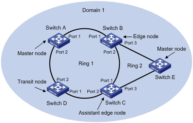
As shown in Figure 1-1, Domain 1 is an RRPP domain, which consists of Ethernet ring 1 and ring 2. All the nodes on the Ethernet rings belong to the RRPP domain.
II. Ethernet ring
An Ethernet ring is a ring-shaped Ethernet topology, on which an RRPP domain is based. An RRPP domain consists of a primary ring and one or more subrings. In configuration, the level of the primary ring is level 0, and that of the subrings is level 1.
As shown in Figure 1-1, RRPP domain 1 consists of ring 1 and ring 2. If their levels are set to level 0 and level 1 respectively, ring 1 is the primary ring and ring 2 is the subring.
Each ring is in one of the following two states:
l Healthy: The physical links of the ring network are connected.
l Broken: A certain physical link is disconnected on the ring network.
III. Control VLAN and data VLAN
l A control VLAN is a special VLAN used to transfer RRPP protocol data units. On each switch, the ports connected with the Ethernet ring belong to the control VLAN, and only the ports connected with the Ethernet ring can be added to the control VLAN. It is not allowed to configure an IP address for the interface of the control VLAN.
l A data VLAN is used to transfer data packets. A data VLAN contains both the ports connected with the Ethernet ring and other ports.
IV. Node
Every switch on an Ethernet ring network is a node. A node can play any of the following roles:
l Master node: The node that initiates ring test and performs data loops prevention. Each ring has one and only one master node.
l Transit node: All nodes other than the master node on a ring are transit nodes.
l Edge node: An edge node is located on the primary ring and a subring at the same time. An edge node serves as a transit node on the primary ring and an edge node on a subring. In an RRPP domain, there are two edge nodes on a subring. You must specify one of them as the assistant edge node.
The role that a node plays depends on your configuration. As shown in Figure 1-1, Switch A is the master node of Ring 1; Switch E is the master node of Ring 2; Switch B, Switch C, and Switch D are transit nodes of Ring 1. Switch B and Switch C are also edge nodes because they are on both Ring 1 and Ring 2. For Switch B and Switch C, you can specify one of them as the edge node, and the other as the assistant edge node.
V. RRPP ports (primary and secondary ports)
The master node and transit nodes each uses two ports to connect to the Ethernet ring: one is the primary port and the other is the secondary port. The port roles are determined by your configuration.
1) The primary and secondary ports on the master node
The master node uses the primary port to transmit ring test packets and uses the secondary port to receive ring test packets.
When an Ethernet ring is in the healthy state, the secondary port of the master node allows only control-VLAN packets to pass and logically blocks data-VLAN packets.
When the Ethernet ring is in the broken state, the secondary port of the master node unblocks and allows data-VLAN packets to pass.
![]() Caution:
Caution:
The ports on the common link of cross-domain intersecting rings cannot be configured as the secondary ports of the master node.
2) The primary and secondary ports on a transit node
The primary port and secondary port of the master node are the same in functionality. Both are used for transmitting RRPPDUs and data packets of the RRPP ring.
The roles of ports are determined by your configuration. As shown in Figure 1-1, Switch A is the master node of Ring 1, and port 1 and port 2 of Switch A are respectively the primary port and the secondary port. Switch B, Switch C and Switch D are the transit nodes of Ring 1. Port 1 and Port 2 of each of the three switches are respectively the primary port and the secondary port of the switch on Ring 1.
![]() Caution:
Caution:
The primary and secondary ports of a transit node are functionally the same. But the ports on the common link of cross-domain intersecting rings cannot be configured as secondary ports.
VI. RRPP ports (common and edge ports)
Among the two ports connecting an edge node to a subring, one is the common port and the other is the edge port of the node. The common port connects the edge node to the primary ring and a subring at the same time. An edge port is connected only with a subring.
The roles of nodes are determined by your configuration. As shown in Figure 1-1, Switch C and Switch D are on both Ring 1 and Ring 2 at the same time. Port 2 of Switch B and port 1 of Switch C are on both primary ring and the subring, and so they are common ports. Port 3 of Switch B and port 3 of Switch C are edge ports, which are on the subring only.
VII. MAC address table
The MAC address table (a Layer 2 forwarding database (FDB)) on a switch is updated through the source MAC address learning function on the switch.
![]() Caution:
Caution:
When MAC address table is deleted, the corresponding ARP entries are also deleted.
VIII. Timer
Two timers, Hello timer and Fail timer, are involved when the master node sends and receives RRPP packets.
l Hello timer: Defines the time interval at which the primary port of the master node sends the health detection packet.
1.1.2 RRPP Packet Type
The following table describes RRPP packet types.
Table 1-1 RRPP protocol packets
|
Packet type |
Remarks |
|
Health detection packet |
The master node sends the health detection packet (HELLO packet) to detect whether the ring network is complete. |
|
LINK UP packet |
A transit node sends this packet to notify the master node that a link is UP on the ring network. |
|
LINK DOWN packets |
A transit node sends this packet to notify the master node that a port is DOWN and the ring is broken. |
|
COMMON-FLUSH-FDB packet |
The master node sends this packet to tell all the transit nodes to refresh their respective MAC address FDB. |
|
COMPLETE-FLUSH-FDB packet |
The master node sends this packet to tell all the transit nodes to refresh their respective MAC address FDB and unblock the ports in the blocked data VLANs. |
|
Edge-Hello packet |
Edge-Hello packets are used to check whether the primary ring operates properly. They are sent by edge nodes, travel in the control VLAN, and conclude their trip on assistant edge nodes. |
|
Major-Fault packet |
Major-Fault packets are used to inform primary ring faults. By default, an assistant edge node sends Major-Fault packets to the control VLAN of the subring through the edge if it receives no edge-hello packet within 4 seconds. |
1.1.3 Typical RRPP Network Topologies
This section presents typical RRPP network topologies. You can choose an appropriate topology for your network.
I. Single ring
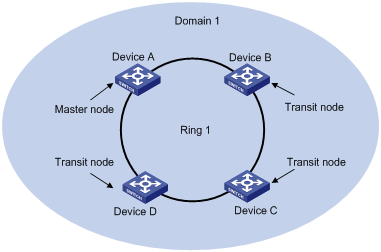
Figure 1-2 Single ring
There is only one ring in the network topology. In this case, you are required to configure only one RRPP domain.
II. Tangent rings

Figure 1-3 Tangent rings
The network comprises two or more rings and any two rings have only one common node. For each ring, you are required to define an independent RRPP domain.
III. Dual homed rings
The network comprises two or more rings and these rings share two common nodes. In this case, you are required to define only one RRPP domain, and configure one ring as the primary ring and the other rings as subrings.
IV. Single-domain intersecting rings
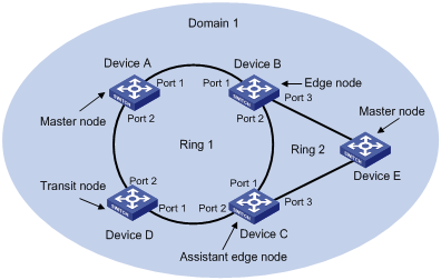
Figure 1-5 Single-domain intersecting rings
The network comprises two or more rings and between any two rings there are two common nodes. If these rings share the same common nodes, dual homed rings are formed. To use the single-domain intersecting rings topology, you can define only one RRPP domain, and configure one ring as the primary ring and the other rings as subrings.
V. Cross-domain intersecting rings
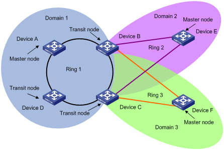
Figure 1-6 Cross-domain intersecting rings
As shown in Figure 1-6, the network comprises two or more domains and between these domains there are two common nodes. In each domain, you must define the ring contain the common nodes as the primary ring. Note that each domain can contain only one primary ring. For intersecting domains, the ring configuration of a domain is independent of that of any other domain. The data VLAN of a domain must be isolated from that of any other domain.
1.1.4 Basic Principles of RRPP
I. Link DOWN notification mechanism
When detecting a port in the RRPP domain is down, a transit node sends the LINK DOWN packet immediately to the master node. After receiving the LINK DOWN packet, the master node unblocks the data VLAN of the secondary port, and sends the COMMON-FLUSH-FDB packet to tell all transit nodes to refresh their respective MAC address FDB.
II. Polling mechanism
The primary port of the master node periodically sends the health detection packet in a control VLAN.
l If the secondary port of the master node receives the health detection packet, this indicates that the ring link is complete, and the master node will keep the secondary port blocked.
l If the secondary port of the master node fails to receive the health detection packet within the predefined timeout time, this indicates that a failure has occurred to the ring link. In this case, the master node unblocks the data VLANs on the secondary port, and sends the COMMON-FLUSH-FDB packet to tell all transit nodes to refresh their respective MAC address FDB.
III. Ring recovery
After the trouble RRPP port on a transit node turns up again, it may take some time for the master node to detect that the ring has recovered. In this time period, a temporary data loop may occur for data VLANs, thus causing broadcast storm.
To avoid such temporary data loop, once a transit node finds that an RRPP port on it turns up again, it blocks the port temporarily (in this case, it allows only control VLAN packets to pass the port), and unblocks the port when it receives a COMPLETE-FLUSH-FDB packet from the master node. If the port that turns up again is a common port of cross-domain Intersecting rings, the node unblocks the port only after it receives COMPLETE-FLUSH-FDB packets from all rings it belongs to.
IV. SRPT check
The SRPT check function is used to prevent loops between subrings in a domain.
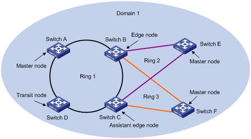
In a dual homed rings topology as shown in Figure 1-4, assume that Ring 1 is the primary ring, and Ring 2 and Ring 3 are subrings. When the two links (one is the common link) on the primary ring are both down, the master nodes on subrings Ring 2 and Ring 3 unblock their own secondary ports. As a result, loops occur between Switch B, Switch C, Switch E, and Switch F, causing broadcast storms. In this case, the assistant edge node of a subring will send Major-Fault frames to the edge node of the subring. Upon receiving the Major-Fault frames, the edge node blocks its edge port to eliminate loops.
Disable SRPT check in a domain that has only one subring. As shown in Figure 1-7, with SRPT check enabled, when the two links (one is the common link) on the primary ring go down, the assistant-edge node of the subring sends Major-Fault frames to the edge node of the subring, and the edge node blocks its edge port upon receiving the Major-Fault frames. As a result, the remaining network part cannot communicate and the user traffic will be isolated. To avoid this problem, you can use the undo srpt-check ring enable command to disable SRPT check for the subring.
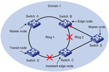
Figure 1-7 Network diagram for SRPT check in a network with a single subring
& Note:
If you are sure that primary-ring failures will not cause loops, disable SRPT check to avoid user traffic isolation due to edge port blocking.
1.2 Master Node Configuration
1.2.1 Configuration Prerequisites
The switch ports on the Ethernet ring have been configured as trunk ports which allow data VLAN packets to pass.
1.2.2 Master Node Configuration Tasks
The following table describes the master node configuration tasks.
Follow these steps to configure the master node:
|
To do ... |
Use the command ... |
Remarks |
|
Enter system view |
system-view |
— |
|
Create an RRPP domain, and enter RRPP domain view |
rrpp domain domain-id |
Required The command prompt of RRPP domain view depends on the domain-id you input. |
|
Specify a control VLAN for the RRPP domain |
control-vlan vlan-id |
Required |
|
Specify the current switch as the master node of a ring, and specify the primary port and the secondary port of the node |
ring ring-id node-mode master primary-port pri-port secondary-port sec-port level level-value |
Required pri-port and sec-port each can be either a single port or a aggregation group. Level 0 identifies the primary ring and level 1 identifies a subring. |
|
Configure RRPP domain timers |
timer hello-timer hello-value fail-timer fail-value |
Optional By default, the Hello timer is set to 1 second, and the Fail timer to 8 seconds. |
|
Enable an RRPP ring |
ring ring-id enable |
Required |
|
Return to system view |
quit |
— |
|
Enable the RRPP protocol |
rrpp enable |
Required |
|
Display the brief information of all RRPP domains configured on the switch |
display rrpp brief |
Optional Available in any view |
|
Display RRPP configuration details on the switch |
display rrpp verbose domain domain-id [ ring ring-id ] |
|
|
Display RRPP packet statistics of the switch |
display rrpp statistics domain domain-id [ ring ring-id ] |
To clear the RRPP statistics information, use the reset rrpp statistics domain domain-id [ ring ring-id ] command.
![]() Caution:
Caution:
l The control VLAN for an RRPP domain must not be a VLAN you have created on the switch, and you are not recommended to configure the same VLAN as both control VLAN and remote-probe VLAN.
l When deleting an RRPP domain by using the undo rrpp domain command, make sure no RRPP ring exists in the RRPP domain.
l When the RRPP ring is in complete state, executing the undo rrpp enable command on the master node will lead to loop, and thus may result in broadcast storm. So, you are recommended to execute the shutdown command on an RRPP port before executing the undo rrpp enable command.
l You are not recommended to configure a loopback port in the RRPP ring network, and you must not configure an RRPP port as a loopback port.
l In a core network, an RRPP device may function as both Layer 2 and Layer 3 core device. In this case, the main control card and interface cards of the RRPP device may be rather busy. Thus, it is recommended to set a relatively large value for the fail-timer. Generally, increasing the fail-timer setting value does not affect the switching time.
l In an RRPP ring network, it is prohibited to configure port priority. To ensure the priority of some types of traffic, you can use the traffic-priority command.
l RRPP is mutually exclusive with Smart Link, STP, and BPDU Tunnel. Do not configure these functions on a port at the same time.
1.2.3 Master Node Configuration Example
I. Network requirements
l Define the switch as a node in RRPP domain 1.
l Define VLAN 4092 as the control VLAN.
l Define the switch as the master node on primary ring 1 in RRPP domain 1, with Ethernet 1/1/1 as the primary port, and Ethernet 1/1/2 as the secondary port.
l Set the Hello timer and Fail timer to 2 seconds and 7 seconds respectively.
II. Configuration procedure
![]() Caution:
Caution:
Make sure the switch ports on the Ethernet ring have been configured as trunk ports which allow data VLAN packets to pass.
<H3C> system-view
[H3C] rrpp domain 1
[H3C-RRPP-Domain1] control-vlan 4092
[H3C-RRPP-Domain1] ring 1 node-mode master primary-port Ethernet1/1/1 secondary-port Ethernet1/1/2 level 0
[H3C-RRPP-Domain1] timer hello-timer 2 fail-timer 7
[H3C-RRPP-Domain1] ring 1 enable
[H3C-RRPP-Domain1] quit
[H3C] rrpp enable
1.3 Transit Node Configuration
1.3.1 Configuration Prerequisites
The switch ports on the Ethernet ring have been configured as trunk ports which allow data VLAN packets to pass.
1.3.2 Transit Node Configuration Tasks
The following table describes the transit node configuration tasks.
Follow these steps to configure a transit node:
|
To do ... |
Use the command ... |
Remarks |
|
Enter system view |
system-view |
— |
|
Create an RRPP domain, and enter RRPP domain view |
rrpp domain domain-id |
Required The command prompt of RRPP domain view depends on the domain-id you input. |
|
Specify a control VLAN for the RRPP domain |
control-vlan vlan-id |
Required |
|
Specify the current switch as the transit node of a ring, and specify the primary port and the secondary port of the node |
ring ring-id node-mode { master | transit } primary-port { interface-type interface-number | link-aggregation agg-id } secondary-port { interface-type interface-number | link-aggregation agg-id } level level-value |
Required pri-port and sec-port each can be either a single port or a aggregation group. Level 0 identifies the primary ring and level 1 identifies a subring. |
|
Enable an RRPP ring |
ring ring-id enable |
Required |
|
Return to system view |
quit |
— |
|
Enable RRPP |
rrpp enable |
Required |
|
Display the brief information of all RRPP domains configured on the switch |
display rrpp brief |
Optional You can execute the display command in any view |
|
Display RRPP configuration details on the switch |
display rrpp verbose domain domain-id [ ring ring-id ] |
|
|
Display the RRPP packet statistics on the switch |
display rrpp statistics domain domain-id [ ring ring-id ] |
To clear the RRPP statistics information, use the reset rrpp statistics domain domain-id [ ring ring-id ] command.
![]() Caution:
Caution:
l The control VLAN for the RRPP domain must not be a VLAN you have created on the switch, and you are not recommended to configure the same VLAN as both control VLAN and remote-probe VLAN. Generally, increasing the fail-timer setting value does not affect the switching time.
l When deleting an RRPP domain by using the undo rrpp domain command, make sure no RRPP ring exists in the RRPP domain.
& Note:
l You are not recommended to configure a loopback port in the RRPP ring network, and you must not configure an RRPP port as a loopback port.
l In a core network, an RRPP device may function as both Layer 2 and Layer 3 core device. In this case, the main control card and interface cards of the RRPP device may be rather busy. Thus, it is recommended to set a relatively large value for the fail-timer.
l In an RRPP ring network, it is prohibited to configure port priority. To ensure the priority of some types of traffic, you can use the traffic-priority command.
1.3.3 Transit Node Configuration Example
I. Network requirements
l Define the switch as a node in RRPP domain 1.
l Define VLAN 4092 as the control VLAN.
l Configure aggregation group 2; add Ethernet 1/1/2 and Ethernet 1/1/3 to this group.
l Define the switch as a transit node on primary ring 1 in RRPP domain 1, with Ethernet 1/1/1 as the primary port and aggregation group 2 as the secondary port.
II. Configuration procedure
![]() Caution:
Caution:
Make sure the switch ports on the Ethernet ring have been configured as trunk ports which allow data VLAN packets to pass.
<H3C> system-view
[H3C] link-aggregation group 2 mode manual
[H3C] interface Ethernet 1/1/2
[H3C-Ethernet1/1/2] port link-aggregation group 2
Please wait...
Done.
[H3C-Ethernet1/1/2] quit
[H3C] interface Ethernet 1/1/3
[H3C-Ethernet1/1/3] port link-aggregation group 2
Please wait...
Done.
[H3C-Ethernet1/1/3] quit
[H3C] rrpp domain 1
[H3C-RRPP-Domain1] control-vlan 4092
[H3C-RRPP-Domain1] ring 1 node-mode transit primary-port Ethernet1/1/1 secondary-port link-aggregation 2 level 0
[H3C-RRPP-Domain1] ring 1 enable
[H3C-RRPP-Domain1] quit
[H3C] rrpp enable
1.4 Edge Node Configuration
1.4.1 Configuration Prerequisites
The switch ports on the Ethernet rings have been configured as trunk ports which allow data VLAN packets to pass.
1.4.2 Edge Node Configuration Tasks
The following table describes the edge node configuration tasks.
Follow these steps to configure the edge node of a subring:
|
To do ... |
Use the command ... |
Remarks |
|
Enter system view |
system-view |
— |
|
Create an RRPP domain, and enter RRPP domain view |
rrpp domain domain-id |
Required The command prompt of RRPP domain view depends on the domain-id you input. |
|
Specify a control VLAN for the RRPP domain |
control-vlan vlan-id |
Required |
|
Specify the current switch as a transit node of the primary ring, and specify the primary port and the secondary port |
ring ring-id node-mode { master | transit } primary-port { interface-type interface-number | link-aggregation agg-id } secondary-port { interface-type interface-number | link-aggregation agg-id } level level-value |
Required The level-value argument is 0. |
|
Specify the current switch as the edge node of a subring, and specify the common port and the edge port |
ring ring-id node-mode edge common-port { interface-type interface-number | link-aggregation agg-id } edge-port { interface-type interface-number | link-aggregation agg-id } |
Required |
|
Enable the primary ring |
ring ring-id enable |
Required |
|
Enable the subring |
ring ring-id enable |
Required |
|
Disable SRPT check for the specified subring |
undo srpt-check ring ring-id enable |
Optional Enabled by default |
|
Return to system view |
quit |
— |
|
Enable RRPP |
rrpp enable |
Required |
|
Display the brief information of all RRPP domains configured on the switch |
display rrpp brief |
Optional You can execute the display command in any view |
|
Display RRPP configuration details on the switch |
display rrpp verbose domain domain-id [ ring ring-id ] |
|
|
Display the RRPP packet statistics on the switch |
display rrpp statistics domain domain-id [ ring ring-id ] |
To clear the RRPP statistics information, use the reset rrpp statistics domain domain-id [ ring ring-id ] command.
![]() Caution:
Caution:
l The control VLAN for the RRPP domain must not be a VLAN you have created on the switch, and you are not recommended to configure the same VLAN as both control VLAN and remote-probe VLAN.
l When deleting an RRPP domain by using the undo rrpp domain command, make sure no RRPP ring exists in the RRPP domain.
l In the same RRPP domain, different rings must not have the same Ring ID.
l When configuring SRPT check, make sure that the state of the SRPT check function is the same on the edge node and the assistant edge node.
& Note:
l You are not recommended to configure a loopback port in the RRPP ring network, and you must not configure an RRPP port as a loopback port.
l In a core network, an RRPP device may function as both Layer 2 and Layer 3 core device. In this case, the main control card and interface cards of the RRPP device may be rather busy. Thus, it is recommended to set a relatively large value for the fail-timer. Generally, increasing the fail-timer setting value does not affect the switching time.
l In an RRPP ring network, it is prohibited to configure port priority. To ensure the priority of some types of traffic, you can use the traffic-priority command.
1.4.3 Edge Node Configuration Example
I. Network requirements
l Configure aggregation group 2; add Ethernet 1/1/2 and Ethernet 1/1/3 to this group.
l Define the switch as a node in RRPP domain 1.
l Define VLAN 4092 as the control VLAN.
l Define the switch as a transit node on primary ring 1 in RRPP domain 1, with Ethernet 1/1/1 as the primary port and aggregation group 2 as the secondary port.
l Define the switch as an edge node on subring 2 in RRPP domain 1, with aggregation group 2 as the common port and Ethernet 1/1/4 as the edge port.
II. Configuration procedure
![]() Caution:
Caution:
Make sure the switch ports on the Ethernet rings have been configured as trunk ports which allow data VLAN packets to pass.
<H3C> system-view
[H3C] link-aggregation group 2 mode manual
[H3C] interface Ethernet 1/1/2
[H3C-Ethernet1/1/2] port link-aggregation group 2
Please wait...
Done.
[H3C-Ethernet1/1/2] quit
[H3C] interface Ethernet 1/1/3
[H3C-Ethernet1/1/3] port link-aggregation group 2
Please wait...
Done.
[H3C-Ethernet1/1/3] quit
[H3C] rrpp domain 1
[H3C-RRPP-Domain1] control-vlan 4092
[H3C-RRPP-Domain1] ring 1 node-mode transit primary-port Ethernet1/1/1 secondary-port link-aggregation 2 level 0
[H3C-RRPP-Domain1] ring 2 node-mode edge common-port link-aggregation 2 edge-port Ethernet 1/1/4
[H3C-RRPP-Domain1] ring 1 enable
[H3C-RRPP-Domain1] ring 2 enable
[H3C-RRPP-Domain1] quit
[H3C] rrpp enable
1.5 Assistant Edge Node Configuration
1.5.1 Configuration Prerequisites
The switch ports on the Ethernet rings have been configured as trunk ports which allow data VLAN packets to pass.
1.5.2 Assistant Edge Node Configuration Tasks
The following table describes the assistant edge node configuration tasks.
Follow these steps to configure the assistant edge node of a subring:
|
To do ... |
Use the command ... |
Remarks |
|
Enter system view |
system-view |
— |
|
Create an RRPP domain, and enter RRPP domain view |
rrpp domain domain-id |
Required The command prompt of RRPP domain view depends on the domain-id you input. |
|
Specify a control VLAN for the RRPP domain |
control-vlan vlan-id |
Required |
|
Specify the current switch as a transit node of the primary ring, and specify the primary port and the secondary port |
ring ring-id node-mode { master | transit } primary-port { interface-type interface-number | link-aggregation agg-id } secondary-port { interface-type interface-number | link-aggregation agg-id } level level-value |
Required For the level-value argument, value 0 refers to the primary ring and value 1 refers to a subring. |
|
Specify the current switch as the assistant edge node of a subring, and specify the common port and the edge port |
ring ring-id node-mode assistant-edge common-port { interface-type interface-number | link-aggregation agg-id } edge-port { interface-type interface-number | link-aggregation agg-id } |
Required |
|
Enable the primary ring |
ring ring-id enable |
Required |
|
Enable the subring |
ring ring-id enable |
Required |
|
Disable SRPT check for the specified subring |
undo srpt-check ring ring-id enable |
Optional Enabled by default |
|
Return to system view |
quit |
— |
|
Enable RRPP |
rrpp enable |
Required |
|
Display the brief information of all RRPP domains configured on the switch |
display rrpp brief |
Optional You can execute the display command in any view |
|
Display RRPP configuration details on the switch |
display rrpp verbose domain domain-id [ ring ring-id ] |
|
|
Display the RRPP packet statistics on the switch |
display rrpp statistics domain domain-id [ ring ring-id ] |
To clear the RRPP statistics information, use the reset rrpp statistics domain domain-id [ ring ring-id ] command.
![]() Caution:
Caution:
l The control VLAN for the RRPP domain must not be a VLAN you have created on the switch, and you are not recommended to configure the same VLAN as both control VLAN and remote-probe VLAN.
l When deleting an RRPP domain by using the undo rrpp domain command, make sure no RRPP ring exists in the RRPP domain on the current switch.
l In the same RRPP domain, different rings must not have the same Ring ID.
l When configuring SRPT check, make sure that the state of the SRPT check function is the same on the edge node and the assistant edge node.
& Note:
l You are not recommended to configure a loopback port in the RRPP ring network, and you must not configure an RRPP port as a loopback port.
l In a core network, an RRPP device may function as both Layer 2 and Layer 3 core device. In this case, the main control card and interface cards of the RRPP device may be rather busy. Thus, it is recommended to set a relatively large value for the fail-timer. Generally, increasing the fail-timer setting value does not affect the switching time.
l In an RRPP ring network, it is prohibited to configure port priority. To ensure the priority of some types of traffic, you can use the traffic-priority command.
1.5.3 Assistant Edge Node Configuration Example
I. Network requirements
l Define the switch as a node in RRPP domain 1.
l Define VLAN 4092 as the control VLAN.
l Define the switch as a transit node on primary ring 1 in RRPP domain 1, with Ethernet 1/1/1 as the primary port and Ethernet 1/1/2 as the secondary port.
l Define the switch as an assistant edge node on subring 2 in RRPP domain 1, with Ethernet 1/1/2 as the common port and Ethernet 1/1/4 as the edge port.
II. Configuration procedure
![]() Caution:
Caution:
Make sure the switch ports on the Ethernet rings have been configured as trunk ports which allow data VLAN packets to pass.
<H3C> system-view
[H3C] rrpp domain 1
[H3C-RRPP-Domain1] control-vlan 4092
[H3C-RRPP-Domain1] ring 1 node-mode transit primary-port Ethernet1/1/1 secondary-port Ethernet1/1/2 level 0
[H3C-RRPP-Domain1] ring 2 node-mode assistant-edge common-port Ethernet 1/1/2 edge-port Ethernet 1/1/4
[H3C-RRPP-Domain1] ring 1 enable
[H3C-RRPP-Domain1] ring 2 enable
[H3C-RRPP-Domain1] quit
[H3C] rrpp enable
1.6 Displaying and Maintaining RRPP
|
To do ... |
Use the command ... |
Remarks |
|
Display brief information about all RRPP domains |
display rrpp brief |
Available in any view |
|
Display detailed information about RRPP configuration |
display rrpp verbose domain domain-id [ ring ring-id ] |
Available in any view |
|
Display RRPP packets statistics |
display rrpp statistics domain domain-id [ ring ring-id ] |
Available in any view |
|
Clear RRPP statistics |
reset rrpp statistics domain domain-id [ ring ring-id ] |
Available in user view |
1.7 RRPP Configuration Examples
For an RRPP ring network carrying VPLS traffic, you are not recommended to configure any port in the RRPP rings as a private VPLS network port. If this is necessary, be sure not to configure the secondary port of the RRPP master node as a private VPLS network port.
1.7.1 Single Ring Network Configuration Example
I. Network requirements
l Switch A, Switch B, Switch C and Switch D form RRPP domain 1.
l The control VLAN of RRPP domain 1 is VLAN 4092.
l Switch A, Switch B, Switch C and Switch D form primary ring 1.
l Switch A serves as the master node of the primary ring, with Ethernet 1/1/1 as the primary port, and Ethernet 1/1/2 as the secondary port.
l Switch B, Switch C and Switch D are transit nodes of the primary ring, with Ethernet 1/1/1 as their primary ports and Ethernet 1/1/2 as their secondary ports.
l The default values are used for the timers on the primary ring.
II. Network diagram
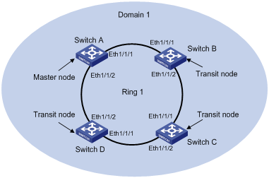
Figure 1-8 Single ring topology
III. Configuration procedure
![]() Caution:
Caution:
Make sure the switch ports on the Ethernet ring have been configured as trunk ports which allow data VLAN packets to pass.
l Configure Switch A
<H3C> system-view
[H3C] rrpp domain 1
[H3C-RRPP-Domain1] control-vlan 4092
[H3C-RRPP-Domain1] ring 1 node-mode master primary-port Ethernet1/1/1 secondary-port Ethernet1/1/2 level 0
[H3C-RRPP-Domain1] ring 1 enable
[H3C-RRPP-Domain1] quit
[H3C] rrpp enable
l Configure Switch B
<H3C> system-view
[H3C] rrpp domain 1
[H3C-RRPP-Domain1] control-vlan 4092
[H3C-RRPP-Domain1] ring 1 node-mode transit primary-port Ethernet1/1/1 secondary-port Ethernet1/1/2 level 0
[H3C-RRPP-Domain1] ring 1 enable
[H3C-RRPP-Domain1] quit
[H3C] rrpp enable
l Configure Switch C
<H3C> system-view
[H3C] rrpp domain 1
[H3C-RRPP-Domain1] control-vlan 4092
[H3C-RRPP-Domain1] ring 1 node-mode transit primary-port Ethernet1/1/1 secondary-port Ethernet1/1/2 level 0
[H3C-RRPP-domain1] ring 1 enable
[H3C-RRPP-domain1] quit
[H3C] rrpp enable
l Configure Switch D
<H3C> system-view
[H3C] rrpp domain 1
[H3C-RRPP-domain1] control-vlan 4092
[H3C-RRPP-domain1] ring 1 node-mode transit primary-port Ethernet1/1/1 secondary-port Ethernet1/1/2 level 0
[H3C-RRPP-domain1] ring 1 enable
[H3C-RRPP-domain1] quit
[H3C] rrpp enable
& Note:
After the above configuration, you can use the display commands to view the RRPP configuration and packet statistics.
1.7.2 Single-Domain Intersecting Ring Network Configuration Example
I. Network requirements
l Switch A, Switch B, Switch C, Switch D, and Switch E form RRPP domain 1.
l The control VLAN of RRPP domain 1 is VLAN 4092.
l Switch A, Switch B, Switch C and Switch D form primary ring 1.
l Switch C, Switch D, and Switch E form subring 2.
l Switch A serves as the master node of the primary ring, with Ethernet 1/1/1 as the primary port and Ethernet 1/1/2 as the secondary port.
l Switch E serves as the master node of the subring, with Ethernet 1/1/1 as the primary port and Ethernet 1/1/2 as the secondary port.
l Switch B serves as a transit node of the primary ring and the edge node of the subring, with Ethernet 1/1/2 as the common port and Ethernet 1/1/3 as the edge port.
l Switch C serves as a transit node of the primary ring and the assistant edge node of the subring, with Ethernet 1/1/1 as the common port and Ethernet 1/1/3 as the edge port.
l Switch D serves as a transit node of the subring, with Ethernet 1/1/1 as the primary port and Ethernet 1/1/2 as the secondary port.
l The default values are used for the timers on the primary ring and the subring.
II. Network diagram
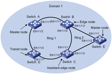
Figure 1-9 Single-domain intersecting ring topology
III. Configuration procedure
![]() Caution:
Caution:
Make sure the switch ports on the Ethernet rings have been configured as trunk ports which allow data VLAN packets to pass.
l Configure Switch A
<H3C> system-view
[H3C] rrpp domain 1
[H3C-RRPP-domain1] control-vlan 4092
[H3C-RRPP-domain1] ring 1 node-mode master primary-port Ethernet1/1/1 secondary-port Ethernet1/1/2 level 0
[H3C-RRPP-domain1] ring 1 enable
[H3C-RRPP-domain1] quit
[H3C] rrpp enable
l Configure Switch B
<H3C> system-view
[H3C] rrpp domain 1
[H3C-RRPP-domain1] control-vlan 4092
[H3C-RRPP-domain1] ring 1 node-mode transit primary-port Ethernet1/1/1 secondary-port Ethernet1/1/2 level 0
[H3C-rrpp-domain1] ring 2 node-mode edge common-port ethernet 1/1/2 edge-port ethernet 1/1/3
[H3C-RRPP-domain1] ring 1 enable
[H3C-RRPP-domain1] ring 2 enable
[H3C-RRPP-domain1] quit
[H3C] rrpp enable
l Configure Switch C
<H3C> system-view
[H3C] rrpp domain 1
[H3C-RRPP-domain1] control-vlan 4092
[H3C-RRPP-domain1] ring 1 node-mode transit primary-port ethernet 1/1/1 secondary-port ethernet 1/1/2 level 0
[H3C-RRPP-domain1] ring 2 node-mode assistant-edge common-port ethernet 1/1/1 edge-port ethernet 1/1/3
[H3C-RRPP-domain1] ring 1 enable
[H3C-RRPP-domain1] ring 2 enable
[H3C-RRPP-domain1] quit
[H3C] rrpp enable
l Configure Switch D
<H3C> system-view
[H3C] rrpp domain 1
[H3C-RRPP-domain1] control-vlan 4092
[H3C-RRPP-domain1] ring 1 node-mode transit primary-port ethernet 1/1/1 secondary-port ethernet 1/1/2 level 0
[H3C-RRPP-domain1] ring 1 enable
[H3C-RRPP-domain1] quit
[H3C] rrpp enable
l Configure Switch E
<H3C> system-view
[H3C] rrpp domain 1
[H3C-RRPP-domain1] control-vlan 4092
[H3C-RRPP-domain1] ring 2 node-mode master primary-port ethernet 1/1/1 secondary-port ethernet 1/1/2 level 1
[H3C-RRPP-domain1] ring 2 enable
[H3C-RRPP-domain1] quit
[H3C] rrpp enable
After the above configuration, you can use the display commands to view the RRPP configuration and packet statistics.
1.7.3 Cross-Domain Intersecting Ring Network Configuration Example
I. Network requirements
l Switch A, Switch B, Switch C, Switch D form RRPP domain 1; Switch E, Switch F, Switch C, and Switch B form RRPP domain 2.
l The control VLAN of RRPP domain 1 is VLAN 4090, and the control VLAN of RRPP domain 2 is VLAN 4092.
l Switch A, Switch B, Switch C, and Switch D form primary ring 1.
l Switch E, Switch F, Switch C, and Switch B form primary ring 2.
l Switch A serves as the master node of the primary ring 1 in domain 1, with Ethernet 1/1/1 as the primary port and Ethernet 1/1/2 as the secondary port.
l Switch E serves as the master node of primary ring 2 in domain 2, with Ethernet 1/1/1 as the primary port and Ethernet 1/1/2 as the secondary port.
l Switch B serves as a transit node of primary ring 1 and a transit node of primary ring 2, with Ethernet 1/1/2 as the common port of the two domains.
l Switch C serves as a transit node of primary ring 1 and a transit node of primary ring 2, with Ethernet 1/1/2 as the common port of the two domains.
l Switch D serves as a transit node of primary ring 1, with Ethernet 1/1/1 as the primary port and Ethernet 1/1/2 as the secondary port.
l Switch F serves as a transit node of primary ring 2 in domain 2, with Ethernet 1/1/1 as the primary port and Ethernet 1/1/2 as the secondary port.
l The default values are used for the timers on the primary ring and the subring.
II. Network diagram
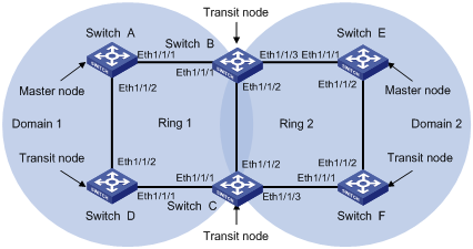
Figure 1-10 Cross-domain intersecting ring topology
III. Configuration procedure
![]() Caution:
Caution:
The switch ports on the Ethernet rings have been configured as trunk ports which allow data VLAN packets to pass. To make sure the data VLANs in different domains are not the same, especially the ports in VLAN 1 (the default VLAN) do not form a ring, execute the undo port trunk permit vlan 1 command on each RRPP port.
l Configure Switch A
<SwitchA> system-view
[SwitchA] rrpp domain 1
[SwitchA-rrpp-domain1] control-vlan 4090
[SwitchA-rrpp-domain1] ring 1 node-mode master primary-port ethernet 1/1/1 secondary-port ethernet 1/1/2 level 0
[SwitchA-rrpp-domain1] ring 1 enable
[SwitchA-rrpp-domain1] quit
[SwitchA] rrpp enable
l Configure Switch B
<SwitchB> system-view
[SwitchB] rrpp domain 1
[SwitchB-rrpp-domain1] control-vlan 4090
[SwitchB-rrpp-domain1] ring 1 node-mode transit primary-port ethernet 1/1/1 secondary-port ethernet 1/1/2 level 0
[SwitchB-rrpp-domain1] ring 1 enable
[SwitchB- rrpp-domain1] quit
[SwitchB] rrpp domain 2
[SwitchB-rrpp-domain2] control-vlan 4092
[SwitchB-rrpp-domain2] ring 2 node-mode transit primary-port ethernet 1/1/2 secondary-port ethernet 1/1/3 level 0
[SwitchB-rrpp-domain2] ring 2 enable
[SwitchB-rrpp-domain2] quit
[SwitchB] rrpp enable
l Configure Switch C
<SwitchC> system-view
[SwitchC] rrpp domain 1
[SwitchC-rrpp-domain1] control-vlan 4090
[SwitchC-rrpp-domain1] ring 1 node-mode transit primary-port ethernet 1/1/1 secondary-port ethernet 1/1/2 level 0
[SwitchC-rrpp-domain1] ring 1 enable
[SwitchC-rrpp-domain1] quit
[SwitchC] rrpp domain 2
[SwitchC-rrpp-domain2] control-vlan 4092
[SwitchC-rrpp-domain2] ring 2 node-mode transit primary-port ethernet 1/1/3 secondary-port ethernet 1/1/2 level 0
[SwitchC-rrpp-domain2] ring 2 enable
[SwitchC-rrpp-domain2] quit
[SwitchC] rrpp enable
l Configure Switch D
<SwitchD> system-view
[SwitchD] rrpp domain 1
[SwitchD-rrpp-domain1] control-vlan 4090
[SwitchD-rrpp-domain1] ring 1 node-mode transit primary-port ethernet 1/1/1 secondary-port ethernet 1/1/2 level 0
[SwitchD-rrpp-domain1] ring 1 enable
[SwitchD-rrpp-domain1] quit
[SwitchD] rrpp enable
l Configure Switch E
<SwitchE> system-view
[SwitchE] rrpp domain 2
[SwitchE-rrpp-domain2] control-vlan 4092
[SwitchE-rrpp-domain2] ring 2 node-mode master primary-port ethernet 1/1/1 secondary-port ethernet 1/1/2 level 0
[SwitchE-rrpp-domain2] ring 2 enable
[SwitchE-rrpp-domain2] quit
[SwitchE] rrpp enable
l Configure Switch F
<SwitchF> system-view
[SwitchF] rrpp domain 2
[SwitchF-rrpp-domain2] control-vlan 4092
[SwitchF-rrpp-domain2] ring 2 node-mode transit primary-port ethernet 1/1/1 secondary-port ethernet 1/1/2 level 0
[SwitchF-rrpp-domain2] ring 2 enable
[SwitchF-rrpp-domain2] quit
[SwitchF] rrpp enable
After the above configuration, you can use the display commands to view the RRPP configuration and packet statistics.