- Table of Contents
-
- H3C S9500 Operation Manual-Release1648[v1.24]-01 Access Volume
- 00-1Cover
- 01-Ethernet Port Configuration
- 02-POS Port Configuration
- 03-Link Aggregation Configuration
- 04-Port Isolation Configuration
- 05-VLAN Configuration
- 06-MAC Address Table Management Configuration
- 07-GVRP Configuration
- 08-QinQ Configuration
- 09-Ethernet Port Loopback Detection Configuration
- 10-DLDP Configuration
- 11-Ethernet OAM Configuration
- 12-Smart Link and Monitor Link Configuration
- 13-MSTP Configuration
- 14-BPDU Tunnel Configuration
- 15-HVRP Configuration
- 16-RRPP Configuration
- 17-RPR Configuration
- Related Documents
-
| Title | Size | Download |
|---|---|---|
| 14-BPDU Tunnel Configuration | 83.5 KB |
Table of Contents
Chapter 1 BPDU Tunneling Configuration
1.2 Configuring BPDU Tunneling
1.2.1 Configuration Prerequisite
1.2.2 Configuring BPDU Tunneling
1.3 BPDU Tunneling Configuration Example
Chapter 1 BPDU Tunneling Configuration
When configuring BPDU tunneling, go to these sections for the information you are interested in:
l BPDU Tunneling Configuration Example
1.1 BPDU Tunneling Overview
The BPDU tunneling feature enables a geographically segmented customer network to transmit bridge protocol data unit (BPDU) packets transparently in the specified virtual local area network (VLAN) across a service provider network. This allows the geographically distributed networks of a customer to participate in a uniform spanning tree calculation while maintaining a separate spanning tree from the service provider network. Currently, the S9500 series switches provide BPDU tunneling and VLAN–VPN tunneling.
l VLAN–VPN tunneling enables a customer network to transmit all types of packets transparently across a service provider network. For detailed information, refer to QinQ Configuration in the Access Volume.
l BPDU tunneling enables a customer network to transmit BPDU packets transparently across a service provider network.
& Note:
At present, the S9500 series switches only support BPDU tunneling for STP packets (in a broad sense). For description about STP packets in a broad sense, refer to the MSTP Configuration in the Access Volume.
As shown in Figure 1-1, the distributed networks of a customer are connected through a service provider network. To allow the customer networks to participate in the same STP calculation, you can configure BPDU tunneling on the edge devices connected the service network to the customer networks. With BPDU tunneling enabled, an edge device replaces the destination MAC address of the arriving BPDUs with a special MAC address and forwards the BPDUs. When the BPDUs arrive at the egress, the egress device replaces the special MAC address with the original destination MAC address and forwards them to the destination. Thus, the BPDUs are transparently forwarded across the service provider network.
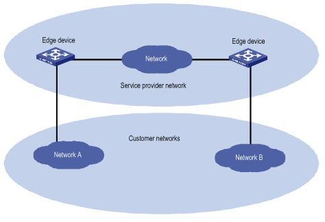
Figure 1-1 BPDU tunneling implementation
1.2 Configuring BPDU Tunneling
1.2.1 Configuration Prerequisite
Ensure that MSTP is properly enabled on the customer networks.
1.2.2 Configuring BPDU Tunneling
Follow these steps to configure BPDU tunneling:
|
Operation |
Command |
Description |
|
Enter system view |
system-view |
— |
|
Enable global BPDU tunneling |
bpdu-tunnel dot1q enable |
Required By default, global BPDU tunneling is disabled. Port-level BPDU tunneling can take effect only after global BPDU tunneling is enabled. |
|
Enter Ethernet port view |
interface interface-type interface-number |
— |
|
Disable the spanning tree protocol on the Ethernet port |
stp disable |
Required |
|
Enable BPDU tunneling on the Ethernet port |
bpdu-tunnel dot1q stp |
Required Disabled by default. |
1.3 BPDU Tunneling Configuration Example
I. Network requirements
l The switches Provider A, Provider B and Provider C act as the access devices of the service provider network.
l The switches Customer A and Customer B act as the access devices of the customer networks.
l Provider A, Provider B and Provider C connect to one another through trunk ports.
l BPDU tunneling feature of STP is enabled on Ethernet port GigabitEthernet 2/1/1 of Provider B
l BPDU tunneling feature of STP is enabled on Ethernet port GigabitEthernet 3/1/3 of Provider C
l STP packets from Customer A and Customer B can be transmitted transparently over the provider network
II. Network diagram
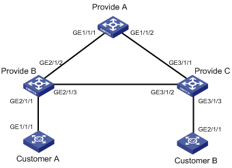
Figure 1-2 Network diagram for BPDU tunneling
III. Configuration procedure
1) Configure Provider A
# Configure ports GigabitEthernet 1/1/1 and GigabitEthernet 1/1/2 as trunk ports and allow VLAN 2 to pass through. Their default VLANs are VLAN 5.
<H3C> system-view
[H3C] interface GigabitEthernet 1/1/1
[H3C-GigabitEthernet1/1/1] port link-type trunk
[H3C-GigabitEthernet1/1/1] port trunk permit vlan 2
[H3C-GigabitEthernet1/1/1] port trunk pvid vlan 5
[H3C-GigabitEthernet1/1/1] interface GigabitEthernet 1/1/2
[H3C-GigabitEthernet1/1/2] port link-type trunk
[H3C-GigabitEthernet1/1/2] port trunk permit vlan 2
[H3C-GigabitEthernet1/1/2] port trunk pvid vlan 5
2) Configure Provider B
# Enable BPDU tunneling feature globally. Configure port GigabitEthernet 2/1/1 as an access port and assign it to VLAN 2. Configure GigabitEthernet 2/1/2 and GigabitEthernet 2/1/3 as trunk ports, and configure VLAN 5 as their default VLAN.
<H3C> system-view
[H3C] bpdu-tunnel dot1q enable
[H3C] interface GigabitEthernet 2/1/1
[H3C-GigabitEthernet2/1/1] port link-type access
[H3C-GigabitEthernet2/1/1] port access vlan 2
[H3C-GigabitEthernet2/1/1] stp disable
[H3C-GigabitEthernet2/1/1] bpdu-tunnel dot1q stp
[H3C-GigabitEthernet2/1/1] interface GigabitEthernet 2/1/2
[H3C-GigabitEthernet2/1/2] port link-type trunk
[H3C-GigabitEthernet2/1/2] port trunk permit vlan 2
[H3C-GigabitEthernet2/1/2] port trunk pvid vlan 5
[H3C-GigabitEthernet1/1/1] interface GigabitEthernet 2/1/3
[H3C-GigabitEthernet2/1/3] port link-type trunk
[H3C-GigabitEthernet2/1/3] port trunk permit vlan 2
[H3C-GigabitEthernet2/1/3] port trunk pvid vlan 5
3) Configure Provider C
# Enable BPDU tunneling feature globally. Configure port GigabitEthernet 3/1/3 as an access port; configure ports GigabitEthernet 3/1/2 and GigabitEthernet 3/1/1 as trunk ports that allow VLAN 2 to pass and configure VLAN 5 as their default VLAN.
<H3C> system-view
[H3C] bpdu-tunnel dot1q enable
[H3C] interface GigabitEthernet 3/1/3
[H3C-GigabitEthernet3/1/3] port link-type access
[H3C-GigabitEthernet3/1/3] port access vlan 2
[H3C-GigabitEthernet3/1/3] stp disable
[H3C-GigabitEthernet3/1/3] bpdu-tunnel dot1q stp
[H3C-GigabitEthernet3/1/3] interface GigabitEthernet 3/1/2
[H3C-GigabitEthernet3/1/2] port link-type trunk
[H3C-GigabitEthernet3/1/2] port trunk permit vlan 2
[H3C-GigabitEthernet3/1/2] port trunk pvid vlan 5
[H3C-GigabitEthernet3/1/2] interface GigabitEthernet 3/1/1
[H3C-GigabitEthernet3/1/1] port link-type trunk
[H3C-GigabitEthernet3/1/1] port trunk permit vlan 2
[H3C-GigabitEthernet3/1/1] port trunk pvid vlan 5