- Table of Contents
-
- H3C S9500 Operation Manual-Release1648[v1.24]-01 Access Volume
- 00-1Cover
- 01-Ethernet Port Configuration
- 02-POS Port Configuration
- 03-Link Aggregation Configuration
- 04-Port Isolation Configuration
- 05-VLAN Configuration
- 06-MAC Address Table Management Configuration
- 07-GVRP Configuration
- 08-QinQ Configuration
- 09-Ethernet Port Loopback Detection Configuration
- 10-DLDP Configuration
- 11-Ethernet OAM Configuration
- 12-Smart Link and Monitor Link Configuration
- 13-MSTP Configuration
- 14-BPDU Tunnel Configuration
- 15-HVRP Configuration
- 16-RRPP Configuration
- 17-RPR Configuration
- Related Documents
-
| Title | Size | Download |
|---|---|---|
| 04-Port Isolation Configuration | 48.76 KB |
Table of Contents
Chapter 1 Port Isolation Configuration
1.2 Configuring Port Isolation
1.2.1 Configuring an Isolation Group
1.2.2 Configuring the Uplink Port in the Isolation Group
1.2.3 Assigning Isolated Ports to the Isolation Group
1.3 Port Isolation Configuration Example
Chapter 1 Port Isolation Configuration
![]() Caution:
Caution:
The LSB1XP4CA0 and LSB1XP4B0 boards do not support port isolation.
When configuring port isolation, go to these sections for information you are interested in:
l Port Isolation Configuration Example
1.1 Port Isolation Overview
Using the port isolation feature, you can place different user ports into the same VLAN. As these users cannot communicate with each other, network security is improved, a flexible networking scheme is provided, and VLAN resources are conserved.
1.2 Configuring Port Isolation
Configuring port isolation involves these tasks:
l Configuring an Isolation Group
l Configuring the Uplink Port in the Isolation Group
l Assigning Isolated Ports to the Isolation Group
& Note:
Layer 3 virtual interfaces cannot be configured on the VLANs where isolated ports are located; otherwise, you will encounter Layer 3 packet forwarding failures.
1.2.1 Configuring an Isolation Group
Follow these steps to configure an isolation group:
|
To do … |
Use the command … |
Remarks |
|
Enter system view |
system-view |
— |
|
Configure an isolation group |
port-isolate group isolate-group-id |
Required Ports in the isolation group can only communicate with the uplink port. The isolated ports and the uplink port must be in the same VLAN. |
|
Query isolation information |
display port-isolate group [ isolate-group-id ] [ verbose ] |
Available in any view |
1.2.2 Configuring the Uplink Port in the Isolation Group
Follow these steps to configure the uplink port in the isolation group:
|
To do … |
Use the command … |
Remarks |
|
Enter system view |
system-view |
— |
|
Enter Ethernet port view or RPR port view |
interface interface-type interface-number |
Required |
|
Configure the uplink port in the isolation group |
port-isolate uplink-port group isolate-group-id |
Required l Only after you have created an isolation group can you configure the uplink port. l The uplink port can only be an Ethernet port or RPR logical interface. l You can configure only one uplink port for one isolation group. The uplink port can be a manual aggregation group, but not a static or dynamic aggregation group. |
|
Query isolation information |
display port-isolate group [ isolate-group-id ] [ verbose ] |
Available in any view |
1.2.3 Assigning Isolated Ports to the Isolation Group
Follow these steps to assign an isolated port to the isolation group:
|
To do … |
Use the command … |
Remarks |
|
Enter system view |
system-view |
— |
|
Enter Ethernet port view or RPR port view |
interface interface-type interface-number |
Required |
|
Assign the port to the isolation group |
port-isolate group isolate-group-id |
Required l Before you can assign isolated ports to an isolation group, you must create the group first. Isolated ports can only be Ethernet ports or RPR logical interfaces. l A port can join only one isolation group. l A port can be either an isolated port or an uplink port, but not both. l If an isolated port is a member of an aggregation group, the other ports in the aggregation group are also members of the isolation group. |
|
Query isolation information |
display port-isolate group [ isolate-group-id ] [ verbose ] |
Available in any view |
1.3 Port Isolation Configuration Example
I. Configuration tasks
User ports Ethernet 4/1/1, Ethernet 4/1/2, and Ethernet 4/1/3 belong to VLAN 100. Configure port isolation to have the three user ports isolated from each other on Layer 2, while being able to communicate with the uplink port GigabitEthernet 3/1/1.
II. Network diagram
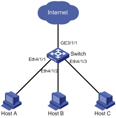
Figure 1-1 Network diagram for port isolation
III. Configuration procedure
# Create VLAN 100, and add Ethernet 4/1/1, Ethernet 4/1/2, and Ethernet 4/1/3 to VLAN 100.
<H3C> system-view
System View: return to User View with Ctrl+Z.
[H3C] vlan 100
[H3C-vlan100] port Ethernet 4/1/1 to Ethernet 4/1/3
[H3C-vlan100] quit
# Create isolation group 1.
[H3C] port-isolate group 1
# Add Ethernet 4/1/1, Ethernet 4/1/2, and Ethernet 4/1/3 to isolation group 1.
[H3C] interface ethernet4/1/1
[H3C-Ethernet4/1/1] port-isolate group 1
[H3C-Ethernet4/1/1] interface ethernet4/1/2
[H3C-Ethernet4/1/2] port-isolate group 1
[H3C-Ethernet4/1/2] interface ethernet4/1/3
[H3C-Ethernet4/1/3] port-isolate group 1
# Configure GigabitEthernet 3/1/1 as a trunk port permitting packets of VLAN 100, and configure it as the uplink port of isolation group 1.
[H3C] interface GigabitEthernet3/1/1
[H3C-GigabitEthernet3/1/1] port link-type trunk
[H3C-GigabitEthernet3/1/1] port trunk permit vlan 100
[H3C-GigabitEthernet3/1/1] port-isolate uplink-port group 1