- Table of Contents
-
- H3C S9500 Operation Manual-Release1648[v1.24]-01 Access Volume
- 00-1Cover
- 01-Ethernet Port Configuration
- 02-POS Port Configuration
- 03-Link Aggregation Configuration
- 04-Port Isolation Configuration
- 05-VLAN Configuration
- 06-MAC Address Table Management Configuration
- 07-GVRP Configuration
- 08-QinQ Configuration
- 09-Ethernet Port Loopback Detection Configuration
- 10-DLDP Configuration
- 11-Ethernet OAM Configuration
- 12-Smart Link and Monitor Link Configuration
- 13-MSTP Configuration
- 14-BPDU Tunnel Configuration
- 15-HVRP Configuration
- 16-RRPP Configuration
- 17-RPR Configuration
- Related Documents
-
| Title | Size | Download |
|---|---|---|
| 11-Ethernet OAM Configuration | 171.54 KB |
Table of Contents
Chapter 1 Ethernet OAM Configuration
1.1.1 Establishing OAM Connection
1.1.3 Diagnosing Remote Faults
1.1.5 Remote MIB Variable Request
1.2.3 Configuring the Error Signal Detection Interval and Error Threshold
1.2.4 Configuring the Error Frame Detection Interval and Error Threshold
1.2.5 Configuring the Error Frame Period Detection Interval and Error Threshold
1.2.6 Configuring the Error Frame Second Detection Interval and Error Threshold
1.2.7 Enabling/Disabling OAM Remote Loopback
1.2.8 Setting the Interval for Sending OAM Hello PDUs
1.2.9 Setting the OAM Link Timeout Time
1.3 Displaying and Maintaining OAM
Chapter 1 Ethernet OAM Configuration
When configuring Ethernet OAM, go to these sections for information you are interested in:
l Displaying and Maintaining OAM
1.1 Ethernet OAM Overview
Operations, administration and maintenance (OAM) is a Layer 2 protocol, used to monitor and solve network problems. OAM can report the network state at the data link layer so that a network administrator can manage the network effectively. Currently, OAM is used to solve OAM problems on Ethernet equipment in the last mile. It can monitor link performance, monitor faults and generate alarms, perform loopback test, and send remote MIB variable requests.
OAM serves as a universal mechanism of interoperation and inter-maintenance between Ethernet equipment. The basic operations include establishing OAM connection, monitoring links, diagnosing remote faults, performing a remote loopback, and sending remote MIB variable requests.
& Note:
Table 1-1 lists the cards that support unidirectional link fault events and remote loopback defined by OAM.
Table 1-1 Cards supporting OAM features
|
Name |
Description |
Support the link fault event or not (packet delivery ratio when a unidirectional link presents) |
Support remote loopback or not |
|
LSB1GP12 |
12-port Gigabit Ethernet optical interface card |
Yes (1%) |
No |
|
LSB1GT12 |
12-port Gigabit Ethernet electrical interface card |
No |
Yes |
|
LSB1GT24 |
24-port Gigabit Ethernet electrical interface card |
No |
Yes |
|
LSB1GP24 |
24-port Gigabit Ethernet optical interface card |
Yes (1%) |
No |
|
LSB1GV48 |
48-port Gigabit Ethernet electrical interface card-1:4-POE |
No |
Yes |
|
LSB1GP48 |
48-port Gigabit Ethernet optical interface card-1:4 |
Yes (1%) |
No |
|
LSB1XK1 |
1-port 10GE optical interface card |
Yes (100%) |
No |
|
LSB1XP2 |
2-port 10GE optical interface card |
Yes (100%) |
No |
|
LSB1XP4L |
4-port 10GE optical interface card |
Yes (100%) |
No |
|
LSB1AHP4G |
2-port OC-3-ATM + 2-port OC-3/12-ATM + 8-port Gigabit optical interface card |
Yes (1%) |
No |
|
LSB1CLP4G |
4-port channelized OC-3-POS + 4-port Gigabit interface card |
Yes (1%) |
No |
|
LSB1ET32G |
32-port channelized E1/T1 electrical interface + 4-port Gigabit optical interface card |
Yes (1%) |
No |
|
LSB1F32G |
32-port fast Ethernet electrical interface + 4-port Gigabit Ethernet optical interface card |
Yes (1%) |
No |
|
LSB1P4G8 |
4-port OC-3c POS optical interface + 8-port Gigabit optical interface card |
Yes (1%) |
No |
|
LSB1GT8P |
8-port Gigabit electrical interface + 4-port Gigabit optical interface card (B) |
Yes (1%) |
Yes |
|
LSB1FW8 |
Firewall card with eight Gigabit optical interfaces |
Yes (1%) |
No |
|
LSB1IPSEC8 |
IPSec card with eight Gigabit optical interfaces |
Yes (1%) |
No |
|
LSB1XP4 |
4-port 10 GE optical interface card-1:2 |
No |
No |
|
LSB1FP20 |
20-port 100 Mbps optical Ethernet interface board |
Yes (100%) |
No |
1.1.1 Establishing OAM Connection
OAM connection is established in the OAM discovery phase. Through OAM connection, interconnected equipment can exchange OAM configuration information and announce the OAM capabilities supported by a local node.
The equipment can establish OAM connection in the active mode or in the passive mode. Table 1-2 compares the processing capabilities of data terminal entity (DTE) in the passive and active mode.
Table 1-2 Comparison between processing capabilities of active DTE and passive DTE
|
Processing capability |
Active DTE |
Passive DTE |
|
Initialize OAM discovery |
Yes |
No |
|
Respond to the initialization of OAM discovery |
Yes |
Yes |
|
Send information OAM protocol data unit (OAMPDU) |
Yes |
Yes |
|
Send event notification PDUs |
Yes |
Yes |
|
Send loopback OAMPDUs |
Yes |
No |
|
Send information OAMPDUs without TLV |
Yes |
Yes |
|
Send variable request OAMPDUs |
Yes |
No |
|
Send variable response OAMPDUs |
Yes, but the peer DTE is required to be in the active mode. |
Yes |
|
Send loopback control OAMPDUs |
Yes |
No |
|
Respond to loopback control OAMPDUs |
Yes, but the peer DTE is required to be in the active mode. |
Yes |
|
Send organization specific OAMPDUs |
Yes |
Yes |
If OAM configurations at both ends are consistent, OAM operation begins at the data link layer.
1.1.2 Link Monitor
Through link monitor, you can detect and find faults in various environments at the data link layer. Link monitor uses event notification PDUs. When a link fault occurs, the local link notifies the OAM entity of the fault after detecting the fault. The following table defines standard link events.
Table 1-3 Standard link events
|
Standard link events |
Definition |
|
Error signal event |
The number of error signals within a fixed period of time exceeds the defined threshold. |
|
Errored frame event |
The number of errored frames within a fixed period of time exceeds the defined threshold. |
|
Errored frame period event |
The number of errored frames received within the period of N frames exceeds the defined threshold. |
|
Errored frame seconds event |
The number of error seconds within M seconds exceeds the defined threshold. |
1.1.3 Diagnosing Remote Faults
Ethernet faults are difficult to diagnose, especially when physical communication is still maintained but network performance is decreasing gradually. OAMPDU defines a flag to allow an OAM entity to send information to the peer. The flag defines an emergency link event supported by OAM. Currently, OAM defines the link fault event, which occurs when the local end can send data, but cannot receive data. In this case, OAMPDUs are sent once every second.
1.1.4 Remote Loopback
A local OAM entity can send a remote loopback OAMPDU to the remote OAM entity, requesting the remote OAM entity to perform loopback. This function can provide necessary help for troubleshooting.
In the loopback mode, all packets except OAMPDUs and pause packets are returned along the way they are sent. Periodical loopback detection can guarantee that current links are smooth. Loopback detection in phases can help you locate specific areas where faults occur.
1.1.5 Remote MIB Variable Request
1.1.6 OAMPDU
The formats of OAMPDUs are as follows.
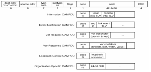
This document involves the following packets:
I. Information OAMPDU
II. Event notification OAMPDU
The event notification OAMPDU is used for link monitoring and is used to notify the remote OAM entity that a fault has occurred to the link.
III. Var request OAMPDU
The Var request OAMPDU is used for variable request, primarily for MIB variables request.
IV. Var response OAMPDU
V. Loopback control OAMPDU
The loopback control OAMPDU is used for remote loopback control. The device can determine whether to send the packet. To implement loopback control, the local DTE sends the loopback control command to the remote DTE. If loopback control is enabled on the remote DTE, the remote DTE returns the packet to the sending entity directly.
1.2 Configuring OAM
Complete the following tasks to configure OAM:
l Configuring the Error Signal Detection Interval and Error Threshold
l Configuring the Error Frame Detection Interval and Error Threshold
l Configuring the Error Frame Period Detection Interval and Error Threshold
l Configuring the Error Frame Second Detection Interval and Error Threshold
l Enabling/Disabling OAM Remote Loopback
l Setting the Interval for Sending OAM Hello PDUs
l Setting the OAM Link Timeout Time
1.2.1 Setting OAM Mode
Follow these steps to configure the OAM mode for the current port:
|
To do … |
Use the command … |
Remarks |
|
Enter system view |
system-view |
— |
|
Enter Ethernet port view |
interface interface-type interface-number |
— |
|
Set OAM mode |
oam ethernet mode { active | passive } |
Optional By default, OAM is set to the passive mode. |
& Note:
l The OAM entity in the active mode can initiate an OAM connection, while the OAM entity in the passive mode can only wait for the connection request sent from the opposite OAM entity.
l You cannot establish an OAM connection between two OAM entities in the passive mode.
l After the OAM function is enabled by entering the oam ethernet enable command, you are not allowed to change the OAM mode. If needed, you can first disable the OAM, then change the OAM mode, and finally enable OAM again.
1.2.2 Enabling OAM
Follow these steps to enable OAM on an Ethernet port:
|
To do … |
Use the command … |
Remarks |
|
Enter system view |
system-view |
— |
|
Enter Ethernet port view |
interface interface-type interface-number |
— |
|
Enable OAM on the current port |
oam ethernet enable |
Required After OAM is enabled, the current Ethernet port starts to establish OAM connection with the peer entity in the preset mode. OAM is disabled by default. |
1.2.3 Configuring the Error Signal Detection Interval and Error Threshold
|
To do … |
Use the command … |
Remarks |
|
Enter system view |
system-view |
— |
|
Configure the error signal detection interval |
oam ethernet errored-symbol period period-value |
Optional The default is 1 second. |
|
Configure the error threshold for creating an error signal event |
oam ethernet errored-symbol threshold threshold-value |
Optional The default is 1. |
|
Display the configuration information |
display oam ethernet configuration |
Available in any view |
& Note:
l If the number of error signals detected on a port over a detection interval is equal to or greater than the error threshold, an error signal event is created.
l After the OAM connection is established, the configured values take effect on all the Ethernet ports automatically.
1.2.4 Configuring the Error Frame Detection Interval and Error Threshold
|
To do … |
Use the command … |
Remarks |
|
Enter system view |
system-view |
— |
|
Configure the error frame detection interval |
oam ethernet errored-frame period period-value |
Optional The default is 1 second. |
|
Configure the error threshold for creating an error frame event |
oam ethernet errored-frame threshold threshold-value |
Optional The default is 1. |
|
Display the configuration information |
display oam ethernet configuration |
Available in any view |
& Note:
l If the number of error frames detected on a port over a detection interval is equal to or greater than the error threshold, an error frame event is created.
l After the OAM connection is established, the configured values take effect on all the Ethernet ports automatically.
1.2.5 Configuring the Error Frame Period Detection Interval and Error Threshold
|
To do … |
Use the command … |
Remarks |
|
Enter system view |
system-view |
— |
|
Configure the error frame period detection interval |
oam ethernet errored-frame-period period period-value |
Optional The default is 1 second. |
|
Configure the error threshold for creating an error frame period event |
oam ethernet errored-frame-period threshold threshold-value |
Optional The default is 1. |
|
Display the configuration information |
display oam ethernet configuration |
Available in any view |
& Note:
l The system converts the configured interval to the maximum number of packets that a port can send over this interval, that is, the maximum number of packets sent serves as the interval.
l If the number of error frames detected on a port over a detection interval is equal to or greater than the error threshold, an error frame period event is created.
l After the OAM connection is established, the configured values take effect on all the Ethernet ports automatically.
1.2.6 Configuring the Error Frame Second Detection Interval and Error Threshold
|
To do … |
Use the command … |
Remarks |
|
Enter system view |
system-view |
— |
|
Configure the error frame second detection interval |
oam ethernet errored-frame-seconds period period-value |
Optional The default is 60 seconds. |
|
Configure the error threshold for creating an error frame second event |
oam ethernet errored-frame-seconds threshold threshold-value |
Optional The default is 1. |
|
Display the configuration information |
display oam ethernet configuration |
Available in any view |
& Note:
l Error frame seconds are the seconds within which error frames are detected.
l The threshold value should not be greater than the corresponding interval; otherwise, no error frame second event can be created.
l If the number of error frame seconds detected on a port over a detection interval is equal to or greater than the error threshold, an error frame second event is created.
l After the OAM connection is established, the configured values take effect on all the Ethernet ports automatically.
1.2.7 Enabling/Disabling OAM Remote Loopback
Follow these steps to perform or remove an OAM remote loopback:
|
To do … |
Use the command … |
Remarks |
|
Enter system view |
system-view |
— |
|
Enter Ethernet port view |
interface interface-type interface-number |
— |
|
Enable OAM remote loopback |
oam ethernet loopback |
Optional OAM remote loopback is disabled by default. |
|
Disable OAM remote loopback |
undo oam ethernet loopback |
Optional OAM remote loopback is disabled by default. |
|
Display the configuration information |
display oam ethernet loopback status |
Available in any view |
& Note:
l The oam ethernet loopback command just triggers loopback, and buildrun is not performed.
l You can perform remote loopback only after establishing the OAM connection; otherwise the system will give an error prompt.
l Remote loopback needs the support of remote hardware. If the remote hardware does not support remote loopback, the system gives a prompt message.
1.2.8 Setting the Interval for Sending OAM Hello PDUs
Follow these steps to set the interval for sending OAM hello PDUs:
|
To do … |
Use the command … |
Remarks |
|
Enter system view |
system-view |
— |
|
Set the interval for sending OAM hello PDUs |
oam ethernet timer hello interval |
Optional By default, the interval for sending OAM hello PDUs is 1,000 ms. |
|
Display the configuration information |
display oam ethernet local |
Available in any view. |
1.2.9 Setting the OAM Link Timeout Time
Follow these steps to set the OAM link timeout time:
|
To do … |
Use the command … |
Remarks |
|
Enter system view |
system-view |
— |
|
Set the OAM link timeout time |
oam ethernet timer keepalive interval |
Optional By default, the OAM link timeout time is 5000 ms. |
|
Display the configuration information |
display oam ethernet local |
Available in any view. |
& Note:
After an OAM link times out, the local end of the Ethernet OAM will age out its connection to the remote OAM entity, resulting in disconnection of the OAM link. In normal conditions, you are recommended to set the timeout time to be longer than the interval for sending Ethernet OAM hello PDUs. Otherwise, a link may disconnect before Ethernet OAM hello PDUs are received, thus causing link instability.
1.3 Displaying and Maintaining OAM
|
To do … |
Use the command … |
Remarks |
|
Display global configuration information of OAM |
display oam ethernet configuration |
Available in any view |
|
Display the statistics about the link events after an OAM sub-layer reset or clear of the statistics |
display oam ethernet link-event { local | remote } [ interface interface-type interface-number ] |
Available in any view |
|
Display the statistics about link events after the establishment of the OAM connection |
display oam ethernet critical-event [ interface interface-type interface-number ] |
Available in any view |
|
Display the information of the OAM connection |
display oam ethernet { local | remote } [ interface interface-type interface-number ] |
Available in any view |
|
Clear the statistics about Ethernet OAMPDUs and link events |
reset oam ethernet [ interface interface-type interface-number ] |
Available in user view |
|
Display the variable information on the peer entity |
display oam ethernet remote variable interface interface-type interface-number |
Available in any view |
& Note:
When specifying a port in any of the commands in this section, note that the interface-type argument must be Ethernet or GigabitEthernet and the interface-number argument must take the form of slot number/port number.
1.4 OAM Configuration Example
I. Network requirements
l Enable the OAM protocol on switches to manage the data link layer.
l Verify link performance by observing error frames received by the switches.
II. Network diagram
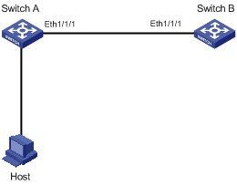
Figure 1-2 Network diagram for OAM configuration
III. Configuration procedure
1) Configure Switch A
# Set Ethernet 1/1/1 in the Passive mode, and then enable OAM.
<H3C>system-view
[H3C] interface ethernet 1/1/1
[H3C-Ethernet1/1/1] oam ethernet mode passive
[H3C-Ethernet1/1/1] oam ethernet enable
[H3C-Ethernet1/1/1] quit
# Configure the error frame detection interval.
[H3C] oam ethernet errored-frame period 20
# Configure the error threshold for creating an error frame event.
[H3C] oam ethernet errored frame threshold 10
# Display the global configuration information of OAM
[H3C] display oam ethernet configuration
Configuration of the link event window/threshold : (s = seconds, f = frames, ms= milliseconds)
--------------------------------------------------------------------------
Errored-symbol Event period : 1(s)
Errored-symbol Event threshold : 1(f)
Errored-frame Event period : 20(s)
Errored-frame Event threshold : 10(f)
Errored-frame-period Event period : 1000(ms)
Errored-frame-period Event threshold : 1(f)
Errored-frame-seconds Event period : 60(s)
Errored-frame-seconds Event threshold : 1(s)
2) Configure Switch B
# Enable OAM on Ethernet 1/1/1. The default OAM mode is Active.
<H3C> system-view
[H3C] interface ethernet 1/1/1
[H3C-Ethernet1/1/1] oam ethernet enable
[H3C-Ethernet1/1/1] quit
# Display the statistics about link events.
[H3C] display oam ethernet link-event remote
Port : Ethernet1/1/1
Link Status : Up
OAMRemoteErrFrameEvent : (s = seconds, f = frames, t = times)
--------------------------------------------------------------------------
Event Time Stamp : 5619(s) Errored Frame Window : 20(s)
Errored Frame Threshold : 10(f) Errored Frame : 1243635(f)
Error Running Total : 85887789(f) Event Running Total : 57(t)