- Table of Contents
-
- H3C S9500 Operation Manual-Release1648[v1.24]-01 Access Volume
- 00-1Cover
- 01-Ethernet Port Configuration
- 02-POS Port Configuration
- 03-Link Aggregation Configuration
- 04-Port Isolation Configuration
- 05-VLAN Configuration
- 06-MAC Address Table Management Configuration
- 07-GVRP Configuration
- 08-QinQ Configuration
- 09-Ethernet Port Loopback Detection Configuration
- 10-DLDP Configuration
- 11-Ethernet OAM Configuration
- 12-Smart Link and Monitor Link Configuration
- 13-MSTP Configuration
- 14-BPDU Tunnel Configuration
- 15-HVRP Configuration
- 16-RRPP Configuration
- 17-RPR Configuration
- Related Documents
-
| Title | Size | Download |
|---|---|---|
| 12-Smart Link and Monitor Link Configuration | 189.06 KB |
Table of Contents
Chapter 1 Smart Link Configuration
1.1.1 Basic Smart Link Concepts
1.1.2 Operating Mechanism of Smart Link
1.2.2 Configuring Smart Link Devices
1.2.3 Configuring Smart Link Associated Devices
1.3 Displaying and Maintaining Smart Link
1.4 Smart Link Configuration Examples
1.4.1 Non-Load-Sharing Smart Link Configuration Example
1.4.2 Load Sharing Smart Link Configuration Example
Chapter 2 Monitor Link Configuration
2.1 Introduction to Monitor Link
2.1.1 Operating Mechanism of Monitor Link
2.1.2 Typical Monitor Link Network Diagram
2.2 Monitor Link Configuration
2.3 Displaying and Maintaining Monitor Link
2.4 Monitor Link Configuration Example
Chapter 3 Smart Link and Monitor Link Configuration Example
3.3.2 Configuring Monitor Link
Chapter 1 Smart Link Configuration
When configuring Smart Link, go to these sections for information that you are interested in:
l Displaying and Maintaining Smart Link
l Smart Link Configuration Examples
1.1 Smart Link Overview
Smart Link is a feature developed to address the slow convergence issue with the Spanning Tree Protocol (STP).
Smart Link is dedicated to dual-uplink networks as shown in Figure 1-1 to provide link redundancy with subsecond convergence. It allows the backup link to take over quickly when the primary link fails. In addition to fast convergence, Smart Link is easy to configure.
1.1.1 Basic Smart Link Concepts

Figure 1-1 Smart Link application scenario
I. Smart link group
A smart link group consists of only two member ports: the master and the slave. At a time, only one port is active for forwarding, and the other port is blocked, that is, in the standby state. When link failure occurs on the active port due to physical fault, OAM connection fault, or presence of unidirectional link for example, the standby port becomes active to take over while the original active port transits to the blocked state.
As shown in Figure 1-1, port 31 and port 32 on Switch C form a smart link group, and port 51 and port 52 on Switch E form another smart link group.
When using Smart Link in conjunction with the Device Link Detection Protocol (DLDP), you are recommended to set DLDP to the auto mode. This is because in the manual mode, DLDP does not perform active/standby link switchover automatically when detecting a unidirectional link.
II. Master port
Master port is a port role in a smart link group. When the link states of both ports in a smart link group are normal, the master port preferentially transits to the forwarding state. Once the master port fails, the slave port takes over to forward traffic. In this case, if the smart link group is not configured with role preemption, the master port stays in standby state until next link switchover even if it has recovered. In Figure 1-1, port 31 is in the active state and is the master port in a smart link group. Port 51 can be the master port of another smart link group, even though it is currently blocked.
III. Slave port
Slave port is the other port role in a smart link group. When the two ports in a smart link group are both in the standby state, the master port takes the precedence to enter the active state. When the master fails, the slave port takes over with the state changing from standby to active. In Figure 1-1, both port 32 and port 51 are slave ports.
IV. Flush message
Link switchover in a smart link group can outdate the current forwarding entries. To adapt to the new topology, network-wide MAC address and ARP table update must be done. A smart link group achieves this by sending flush messages to notify other devices to update the address table.
For example, in Figure 1-1, assume that a link switchover occurs on Switch C and port 32 switches to the active state. In this scenario, Switch C encapsulates information about the VLANs carried on port 31 in flush messages and sends the flush messages through port 32. Switch D receives the flush messages through port 42 and forwards the flush messages to port 41 and port 43. Switch D also refreshes its address tables at the same time. It is the same case with other devices receiving the flush messages.
& Note:
As flush messages are transmitted in the control VLAN, you need to make sure the control VLAN is properly created, which can be done in one of the following two ways.
l Configuring the control VLAN in smart link view first, creating the control VLAN in system view, and then adding the member ports of the smart link group to the control VLAN.
l Creating a VLAN, then adding the member ports of the smart link group to this VLAN, and then configuring this VLAN as the control VLAN in smart link view.
V. Role Preemption
In a smart link group not configured with role preemption, when the slave port is forwarding traffic due to a link switchover, the master port stays in standby state until next link switchover even if it has recovered; in a smart link group configured with role preemption, when the primary link recovers, the master port takes over the traffic immediately, while the slave port enters the standby state.
VI. Protected MSTIs
If smart link groups are used for load sharing, traffic will be distributed on the active ports in the groups. This is achieved by binding MST instances (MSTIs) with these smart link groups. As these MSTIs are protected against loops, they are called protected MSTIs.
1.1.2 Operating Mechanism of Smart Link
The following takes the networking illustrated in Figure 1-1 as an example to describe the smart link mechanism.
On Switch C, the link connected with port 31 is the active link, and that connected with port 32 is the standby link. Normally, port 31 is in the active state, and port 32 is in the standby state. When the link connected with port 31 fails due to a port down event, OAM connection fault, or unidirectional link fault for example, port 31 switches to the standby state and port 32 switches to the active state. The active/standby link can be a single link or an aggregation link. An aggregation link fault occurs only when all the links in the aggregation group fail.
A link switchover can outdate the forwarding entries (including MAC entries and ARP entries) on the devices in the network. To update the forwarding entries, the following two mechanisms are used:
l Traffic-triggered MAC address and ARP table updating.
l The smart link device sends flush messages through the new link.
In the first approach, update is triggered by bidirectional traffic; it is suitable where the device is working with devices of other vendors. The second approach requires that all the uplink devices be able to recognize smart link flush messages for MAC address and ARP table update.
1.2 Smart Link Configuration
1.2.1 Configuration Procedure
1) Configure smart link devices
Smart link devices refer to devices that support smart link functions, have a smart link group configured on them and send flush messages from a specific control VLAN. Switch C and Switch E in Figure 1-1 are examples of smart link devices.
2) Configure smart link associated devices
Smart link associated devices refer to devices that support Smart Link and must be configured to receive and process the flush messages received in the control VLAN in order to work with the smart link devices. Switch A, Switch B and Switch D in Figure 1-1 are examples of associated devices.
When configuring the flush message processing capability on the associated devices, you only need to configure the ports on the active/standby links between the smart link devices and the destination device.
1.2.2 Configuring Smart Link Devices
You are recommended to disable the two ports to be added to a smart link group to prevent possible loops (which may result in broadcast storms) during the configuration.
Follow these steps to configure a smart link device:
|
To do... |
Use the command... |
Remarks |
|
Enter system view |
system-view |
— |
|
Create a smart link group and enter smart link group view |
smart-link group id |
Required The prompt of smart link group view depends on the smart link group ID. |
|
Configure the preemption mode in the smart link group |
preemption mode role |
Required when the smart link group is used for load sharing. |
|
Configure the protected MSTIs of the smart link group |
protected-instance instance-list |
Required If no MSTI is configured, you cannot configure the member ports of the smart link group. |
|
Configure a port as the master port of the smart link group |
port interface-type interface-number master |
Required Use either command. |
|
Configure a manual aggregation group as the master port of the smart link group |
link-aggregation group id master |
|
|
Configure a port as the slave port of the smart link group |
port interface-type interface-number slave |
Required Use either command. |
|
Configure a manual aggregation group as the slave port of the smart link group |
link-aggregation group id slave |
|
|
Configure the control VLAN for sending flush messages |
flush enable [ control-vlan id ] |
Optional By default, VLAN 1 is the control VLAN. You must assign the smart link ports to the control VLAN. |
![]() Caution:
Caution:
l Make sure the ports (or aggregation groups) to be configured as smart link group member ports are not monitor link group member ports.
l Smart Link is mutually exclusive with STP, BPDU tunnel, and RRPP on a port. Before assigning a port to a smart link group, ensure that all these features are disabled on it.
l A single port can be configured as a smart link group member either in port view or in smart link group view. However an aggregation group can be configured as a smart link group member in smart link group view only.
l The control VLAN of a smart link group cannot be the control VLAN or a sub-VLAN of RRPP.
l The control VLAN of a smart link group can only be a static VLAN. Do not configure a VLAN dynamically learned through GVRP as the control VLAN of a smart link group.
l When multiple smart link groups are configured for load sharing, you are recommended to configure them to cover protected MSTIs 0 to 48.
l After you upgrade the software of the switch to a version that supports load sharing among smart link groups, the system automatically assigns the ports you assigned to a smart link group before the upgrade to the smart link group (currently without protected MSTIs) and binds the group with MSTIs 0 to 48.
1.2.3 Configuring Smart Link Associated Devices
Follow these steps to configure a smart link associated device:
|
To do... |
Use the command... |
Remarks |
|
|
Enter system view |
system-view |
— |
|
|
Enable the flush message processing capability |
Enable the capability globally |
smart-link flush enable [ control-vlan id ] |
Required Use either approach. By default, the flush messages processing capability is disabled. If no control VLAN is specified, VLAN 1 is used. |
|
Enable the capability on a port |
interface interface-type interface-number |
||
|
smart-link flush enable [ control-vlan id ] |
|||
1.3 Displaying and Maintaining Smart Link
|
To do... |
Use the command... |
Remarks |
|
Display the information of all smart link groups |
display smart-link group all |
Available in any view |
|
Display the information of a smart link group |
display smart-link group id |
Available in any view |
|
Display the statistics about flush messages |
display smart-link flush |
Available in any view |
|
Clear the statistics about flush messages |
reset smart-link packets counter |
Available in user view |
1.4 Smart Link Configuration Examples
1.4.1 Non-Load-Sharing Smart Link Configuration Example
I. Network requirements
Switch C and Switch E are dually uplinked to Switch A.
II. Network diagram

Figure 1-2 Smart Link network diagram
III. Configuration procedure
# Configure Switch C.
<H3C> system-view
[H3C] vlan 4092
[H3C-vlan 4092] quit
[H3C] smart-link group 1
[H3C-smlk-group1] protected-instance 0 to 48
[H3C-smlk-group1] port ethernet1/1/1 master
[H3C-smlk-group1] port ethernet1/1/2 slave
[H3C-smlk-group1] flush enable control-vlan 4092
[H3C-smlk-group1] quit
[H3C] interface ethernet1/1/1
[H3C-Ethernet1/1/1] port link-type trunk
[H3C-Ethernet1/1/1] port trunk permit vlan 4092
[H3C-Ethernet1/1/1] quit
[H3C] interface ethernet1/1/2
[H3C-Ethernet1/1/2] port link-type trunk
[H3C-Ethernet1/1/2] port trunk permit vlan 4092
# Configure Switch B.
<H3C> system-view
[H3C] interface ethernet1/1/1
[H3C-Ethernet1/1/1] port link-type trunk
[H3C-Ethernet1/1/1] port trunk permit vlan 4092
[H3C-Ethernet1/1/1] smart-link flush enable control-vlan 4092
[H3C-Ethernet1/1/1] quit
[H3C] interface ethernet1/1/2
[H3C-Ethernet1/1/2] port link-type trunk
[H3C-Ethernet1/1/2] port trunk permit vlan 4092
[H3C-Ethernet1/1/2] smart-link flush enable control-vlan 4092
[H3C-Ethernet1/1/2] quit
[H3C] interface ethernet1/1/3
[H3C-Ethernet1/1/3] port link-type trunk
[H3C-Ethernet1/1/3] port trunk permit vlan 4092
[H3C-Ethernet1/1/3] smart-link flush enable control-vlan 4092
# Configure Switch A, Switch D and Switch E.
The configuration on Switch E is similar to that on Switch C.
The configuration on Switch A and Switch D are similar to that on Switch D.
1.4.2 Load Sharing Smart Link Configuration Example
I. Network requirements
Switch C and Switch E are dually uplinked to Switch A.
Configure load balancing Smart Link on Switch C and Switch E as follows:
l Configure two smart link groups (1 and 2), both with role preemption enabled.
l Assign ports Ethernet1/1/1 and Ethernet1/1/2 to smart link group 1 as the master and the slave respectively and to smart link group 2 as the slave and the master respectively.
l Bind smart link group 1 with protected MSTIs 0 through 24 and map VLANs 1 to 200 and VLANs 801 to 1000 to MSTI 1. Bind smart link group 2 with protected MSTIs 25 to 48 and map VLANs 201 to 800 to MSTI 25.
l Use VLAN 4092 as the flush control VLAN and map it to MSTI 1.
II. Network diagram
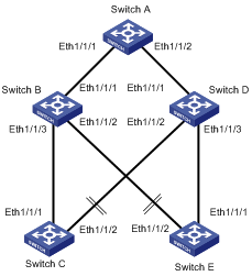
Figure 1-3 Load-sharing smart link network diagram
III. Configuration procedure
# Configure Switch C and Switch E.
<H3C> system-view
[H3C-vlan4092] quit
[H3C] smart-link group 1
[H3C-smlk-group1] preemption mode role
[H3C-smlk-group1] protected-instance 0 to 24
[H3C-smlk-group1] port ethernet1/1/1 master
[H3C-smlk-group1] port ethernet1/1/2 slave
[H3C-smlk-group1] flush enable control-vlan 4092
[H3C-smlk-group1] quit
[H3C] smart-link group 2
New smart-link group created.
[H3C-smlk-group2] preemption mode role
[H3C-smlk-group2] protected-instance 25 to 48
[H3C-smlk-group2] port ethernet1/1/2 master
[H3C-smlk-group2] port ethernet1/1/1 slave
[H3C-smlk-group2] flush enable control-vlan 4092
[H3C-smlk-group2] quit
[H3C] interface ethernet1/1/1
[H3C-Ethernet1/1/1] port link-type trunk
[H3C-Ethernet1/1/1] port trunk permit vlan 1 to 1000 4092
[H3C-Ethernet1/1/1] quit
[H3C] interface ethernet1/1/2
[H3C-Ethernet1/1/2] port link-type trunk
[H3C-Ethernet1/1/2] port trunk permit vlan 1 to 1000 4092
[H3C-Ethernet1/1/2] quit
[H3C] stp region-configuration
[H3C-mst-region] instance 1 vlan 1 to 200 801 to 1000 4092
Info: The new configuration won't be active until you activate it.
[H3C-mst-region] instance 25 vlan 201 to 800
Info: The new configuration won't be active until you activate it.
[H3C-mst-region] active region-configuration
After finishing configuring the smart link devices, configure the associated devices (Switch A, Switch B and Switch D) as described in section Configuring Smart Link Associated Devices for Smart Link to work properly.
Chapter 2 Monitor Link Configuration
When configuring Monitor Link, go to these sections for information you are interested in:
l Introduction to Monitor Link
l Displaying and Maintaining Monitor Link
l Monitor Link Configuration Example
2.1 Introduction to Monitor Link
Monitor link is a port collaboration solution introduced to complement smart link. It is used to monitor uplinks.
Monitor link is implemented through monitor link groups.
A monitor link group consists of an uplink port and multiple downlink ports.
Members of a monitor group can be single ports, static aggregation groups, manual aggregation groups, or smart link groups. Note that a smart link group in a monitor group can only serve as the uplink.
2.1.1 Operating Mechanism of Monitor Link
When the uplink of a monitor link group fails, the downlink ports in the monitor link group are shut down forcibly. When the uplink recovers, all the downlink ports in the group go up again.
2.1.2 Typical Monitor Link Network Diagram

Figure 2-1 A Monitor Link implementation
On Switch B, port 21 is configured as the uplink port of a monitor link group. Port 22 and 23 are configured as the downlink ports of the monitor link group. When link fault occurs on port 21, port 22 and 23 are shut down, thus achieving rapid link switchover.
2.2 Monitor Link Configuration
2.2.1 Configuring the Uplink
Follow these steps to configure the uplink of a monitor link group:
|
To do... |
Use the command... |
Remarks |
|
Enter system view |
system-view |
— |
|
Create a monitor link group and enter monitor link group view |
monitor-link group id |
Required |
|
Configure a single port as the uplink port |
port interface-type interface-number uplink |
Required Use any of the commands |
|
Configure a link aggregation group as the uplink port |
link-aggregation group id uplink |
|
|
Configure a smart link group as the uplink port |
smart-link group id uplink |
|
|
Return to system view |
quit |
— |
2.2.2 Configuring Downlinks
Follow these steps to configure the downlinks of a monitor link group:
|
To do... |
Use the command... |
Remarks |
|
Enter system view |
system-view |
— |
|
Create a monitor link group and enter monitor link group view |
monitor-link group id |
Required |
|
Configure a single port as a downlink port |
port interface-type interface-number downlink |
Required Use either command. Repeat the step to add multiple downlink ports. |
|
Configure a link aggregation group as a downlink port |
link-aggregation group id downlink |
|
|
Return to system view |
quit |
— |
![]() Caution:
Caution:
l When adding a port or a link aggregation group to a monitor link group, make sure it is not a member port of a smart link group.
l Before removing a monitor link group by using the undo monitor-link group command, make sure it contains no member port.
2.3 Displaying and Maintaining Monitor Link
|
To do... |
Use the command... |
Remarks |
|
Display information about a monitor link group |
display monitor-link group { id | all } |
Available in any view |
|
Enable monitor link debugging |
debugging monitor-link [ group id ] { all | error | event } |
Available in user view |
|
Disable monitor link debugging |
undo debugging monitor-link [ group id ] { all | error | event } |
Available in user view |
2.4 Monitor Link Configuration Example
I. Network requirements
On the network shown in Figure 2-2, configure a monitor link group on Switch B, specifying Ethernet1/1/1 as the uplink port and Ethernet1/1/2 and Ethernet1/1/3 as the downlink ports.
II. Network diagram
Figure 2-2 Network diagram for Monitor Link configuration
III. Configuration procedure
<H3C> system-view
[H3C] monitor-link group 1
[H3C-mtlk-group1] port Ethernet 1/1/1 uplink
[H3C-mtlk-group1] port Ethernet 1/1/2 downlink
[H3C-mtlk-group1] port Ethernet 1/1/3 downlink
[H3C-mtlk-group1] quit
Chapter 3 Smart Link and Monitor Link Configuration Example
3.1 Network Requirements
As shown in Figure 3-1, Switch C and Switch E are dually uplinked to Switch B and Switch D.
Configure Smart Link to achieve uplink redundancy, using VLAN 4092 as the control VLAN for flush messages. Configure the Monitor Link function to monitor the links from Switch B, and Switch D to Switch A.
3.2 Network Diagram
Figure 3-1 Network diagram for the cooperation of Smart Link with Monitor Link
3.3 Configuration Procedure
3.3.1 Configuring Smart Link
# Configure a smart link group on Switch C (assuming that Port 31 is Ethernet1/1/1 and port 32 is Ethernet1/1/2).
<H3C> system-view
[H3C] vlan 4092
[H3C-vlan4092] quit
[H3C] smart-link group 1
[H3C-smlk-group] port ethernet1/1/1 master
[H3C-smlk-group] port ethernet1/1/2 slave
[H3C-smlk-group] flush enable control-vlan 4092
[H3C-smlk-group] quit
[H3C] interface ethernet1/1/1
[H3C- Ethernet1/1/1] port link-type trunk
[H3C-Ethernet1/1/1] port trunk permit vlan 4092
[H3C-Ethernet1/1/1] quit
[H3C] interface ethernet1/1/2
[H3C-Ethernet1/1/2] port link-type trunk
[H3C-Ethernet1/1/2] port trunk permit vlan 4092
# Configure a smart link group on Switch E (assuming that Port 51 is Ethernet1/1/1 and Port 52 is Ethernet1/1/2)
<H3C> system-view
[H3C] vlan 4092
[H3C-vlan4092] quit
[H3C] smart-link group 1
[H3C-smlk-group] port ethernet1/1/1 slave
[H3C-smlk-group] port ethernet1/1/2 master
[H3C-smlk-group] flush enable control-vlan 4092
[H3C-smlk-group] quit
[H3C] interface ethernet1/1/1
[H3C-Ethernet1/1/1] port link-type trunk
[H3C-Ethernet1/1/1] port trunk permit vlan 4092
[H3C-Ethernet1/1/1] quit
[H3C] interface ethernet1/1/2
[H3C-Ethernet1/1/2] port link-type trunk
[H3C-Ethernet1/1/2] port trunk permit vlan 4092
# Configure smart link related configuration on Switch B (assuming that Port 21 is GigabitEthernet2/1/1, Port 22 is GigabitEthernet2/1/2 and port 23 is GigabitEthernet2/1/3).
<H3C> system-view
[H3C] vlan 4092
[H3C-vlan4092] quit
[H3C] interface GigabitEthernet2/1/1
[H3C-GigabitEthernet2/1/1] port link-type trunk
[H3C-GigabitEthernet2/1/1] port trunk permit vlan 4092
[H3C-GigabitEthernet2/1/1] quit
[H3C] interface GigabitEthernet2/1/2
[H3C-GigabitEthernet2/1/2] port link-type trunk
[H3C-GigabitEthernet2/1/2] port trunk permit vlan 4092
[H3C-GigabitEthernet2/1/2] quit
[H3C] interface GigabitEthernet2/1/3
[H3C-GigabitEthernet2/1/3] port link-type trunk
[H3C-GigabitEthernet2/1/3] port trunk permit vlan 4092
[H3C-Ethernet2/1/3] quit
[H3C] smart-link flush enable control-vlan 4092
# Configure smart link related configuration on Switch D (assuming that Port 41 is GigabitEthernet4/1/1, port 42 is GigabitEthernet4/1/2, and port 43 is GigabitEthernet4/1/3).
<H3C> system-view
[H3C] vlan 4092
[H3C-vlan4092] quit
[H3C] interface GigabitEthernet4/1/1
[H3C-GigabitEthernet4/1/1]port link-type trunk
[H3C-GigabitEthernet4/1/1]port trunk permit vlan 4092
[H3C-GigabitEthernet4/1/1] quit
[H3C] interface GigabitEthernet4/1/2
[H3C-GigabitEthernet4/1/2] port link-type trunk
[H3C-GigabitEthernet4/1/2] port trunk permit vlan 4092
[H3C-GigabitEthernet4/1/2] quit
[H3C]interface GigabitEthernet4/1/3
[H3C-GigabitEthernet4/1/3] port link-type trunk
[H3C-GigabitEthernet4/1/3] port trunk permit vlan 4092
[H3C-GigabitEthernet4/1/3] quit
[H3C] smart-link flush enable control-vlan 4092
# Configure smart link related configuration on Switch A (assuming that Port 11 is GigabitEthernet1/1/1 and port 12 is GigabitEthernet1/1/2).
<H3C> system-view
[H3C] vlan 4092
[H3C-vlan4092] quit
[H3C] interface GigabitEthernet1/1/1
[H3C-GigabitEthernet1/1/1] port link-type trunk
[H3C-GigabitEthernet1/1/1] port trunk permit vlan 4092
[H3C-GigabitEthernet1/1/1] quit
[H3C]interface GigabitEthernet1/1/2
[H3C-GigabitEthernet1/1/2]port link-type trunk
[H3C-GigabitEthernet1/1/2]port trunk permit vlan 4092
[H3C-GigabitEthernet1/1/2] quit
[H3C] smart-link flush enable control-vlan 4092
After the configuration is completed, you can use the display command to view the smart link configuration and packet statistics.
3.3.2 Configuring Monitor Link
# Configure a monitor link group on Switch B. Add Port 21, Port 22, and Port 23 to the monitor link group (assuming that Port 21 is GigabitEthernet2/1/1, port 22 is GigabitEthernet2/1/2, and port 23 is GigabitEthernet2/1/3).
<H3C> system-view
[H3C] monitor-link group 1
[H3C-mtlk-group1] port GigabitEthernet 2/1/1 uplink
[H3C-mtlk-group1] port GigabitEthernet 2/1/2 downlink
[H3C-mtlk-group1] port GigabitEthernet 2/1/3 downlink
[H3C-mtlk-group1] quit
# Configure a monitor link group on Switch D. Add Port 41, Port 42, and Port 43 to the monitor link group (assuming that Port 41 is GigabitEthernet4/1/1, port 42 is GigabitEthernet4/1/2, and port 43 is GigabitEthernet4/1/3).
<H3C> system-view
[H3C] monitor-link group 1
[H3C-mtlk-group1] port GigabitEthernet 4/1/1 uplink
[H3C-mtlk-group1] port GigabitEthernet 4/1/2 downlink
[H3C-mtlk-group1] port GigabitEthernet 4/1/3 downlink
[H3C-mtlk-group1] quit
After the configuration is completed, you can use the display command to view the Monitor Link configuration.