- Table of Contents
-
- H3C S9500 Operation Manual-Release1648[v1.24]-01 Access Volume
- 00-1Cover
- 01-Ethernet Port Configuration
- 02-POS Port Configuration
- 03-Link Aggregation Configuration
- 04-Port Isolation Configuration
- 05-VLAN Configuration
- 06-MAC Address Table Management Configuration
- 07-GVRP Configuration
- 08-QinQ Configuration
- 09-Ethernet Port Loopback Detection Configuration
- 10-DLDP Configuration
- 11-Ethernet OAM Configuration
- 12-Smart Link and Monitor Link Configuration
- 13-MSTP Configuration
- 14-BPDU Tunnel Configuration
- 15-HVRP Configuration
- 16-RRPP Configuration
- 17-RPR Configuration
- Related Documents
-
| Title | Size | Download |
|---|---|---|
| 05-VLAN Configuration | 164.4 KB |
1.2.1 Creating/Deleting a VLAN
1.2.2 Specifying a Description for a VLAN or VLAN interface
1.2.4 Shutting down/Bringing up a VLAN Interface
1.2.5 Configuring Port-Based VLAN
1.3 Displaying and Maintaining VLAN
1.4 Overview of Protocol-Based VLAN and IP Subnet-Based VLAN
1.5 Configuring Protocol-Based VLAN
1.5.2 Configuring a Protocol VLAN
1.5.3 Applying a Protocol-Based VLAN to a Port
1.6 Displaying Protocol-Based VLAN Configuration
1.7 Configuring an IP Subnet-Based VLAN
1.7.2 Configuring an IP Subnet-Based VLAN
1.7.3 Applying an IP Subnet-Based VLAN to a Port
1.8 Displaying and Maintaining IP Subnet-Based VLAN Configuration
1.9 VLAN Configuration Examples
1.9.1 VLAN Configuration Example
1.9.2 Protocol-Based VLAN and IP Subnet-Based VLAN Configuration Example
Chapter 2 Super VLAN Configuration
2.3 Super VLAN Configuration Example
Chapter 3 Isolate-User-VLAN Configuration
3.1 Isolate-User-VLAN Overview
3.2 Configuring an Isolate-User-VLAN
3.2.2 Configuring an Isolate-User-VLAN
3.2.3 Configuring a Secondary VLAN
3.2.4 Mapping an Isolate-User-VLAN to Secondary VLANs
3.3 Displaying and Maintaining Isolate-User-VLANs
3.4 Isolate-User-VLAN Configuration Example
Chapter 1 VLAN Configuration
When configuring VLAN, go to these sections for information you are interested in:
l Displaying and Maintaining VLAN
l Overview of Protocol-Based VLAN and IP Subnet-Based VLAN
l Configuring Protocol-Based VLAN
l Displaying Protocol-Based VLAN Configuration
l Configuring an IP Subnet-Based VLAN
l Displaying and Maintaining IP Subnet-Based VLAN Configuration
1.1 VLAN Overview
A virtual local area network (VLAN) groups the devices in a LAN logically, not physically, into segments to form virtual workgroups. IEEE issued the IEEE 802.1Q in 1999 to standardize the VLAN implementations.
The VLAN technology allows network administrators to logically divide a physical LAN into different broadcast domains or the so-called virtual LANs. Every VLAN contains a group of workstations with the same demands. The workstations, physically separated, are not necessarily on the same physical LAN segment.
You can establish VLANs of the following types on switches:
l Port-based
l MAC address-based
l IP multicast-based (A multicast group can be a VLAN.)
l Network layer-based (A VLAN can be established by the network layer addresses or protocols of the hosts.)
With the VLAN technology, the broadcast and unicast traffic within a VLAN will not be forwarded to other VLANs. This is helpful to control network traffic, save device investment, simplify network management and enhance security.
1.2 Configuring VLAN
The following sections describe VLAN configuration tasks:
l Specifying a Description for a VLAN or VLAN interface
l Shutting down/Bringing up a VLAN Interface
1.2.1 Creating/Deleting a VLAN
You can use the following commands to create/delete a VLAN. If the VLAN to be created exists, the system will enter the VLAN view directly. Otherwise, the system will create the VLAN first, and then enter the VLAN view.
|
To do… |
Use the command… |
Remarks |
|
Create a VLAN and enter the VLAN view |
vlan vlan-id |
Available in system view |
|
Create VLANs in batch |
vlan vlan-id-list |
Available in system view |
|
Delete an VLAN or VLANs |
undo vlan { vlan-id [ to vlan-id ] | all } |
Available in system view |
![]() Caution:
Caution:
l VLAN 1 is the system-default VLAN and cannot be removed.
l VLANs with their ports being VLAN VPN-enabled cannot be removed.
l Guest VLANs cannot be deleted.
l Protocol-enabled VLANs cannot be deleted.
l Dynamic VLANs cannot be deleted, and the system does not play the prompt when you attempt to delete dynamic VLAN(s).
1.2.2 Specifying a Description for a VLAN or VLAN interface
|
To do… |
Use the command… |
Remarks |
|
Specify a description for a VLAN or VLAN interface |
description string |
Available in VLAN view or VLAN interface view |
|
Restore the default description of the current VLAN or VLAN interface |
undo description |
Available in VLAN view or VLAN interface view |
By default, the description of a VLAN is the VLAN ID of the VLAN, such as VLAN 0001. The description of a VLAN interface is the VLAN interface name, such as Vlan-interface1 Interface.
1.2.3 Naming the Current VLAN
|
To do… |
Use the command… |
Remarks |
|
Name the current VLAN |
name string |
Available in VLAN view |
|
Restore the default name of the current VLAN |
undo name |
Available in VLAN view |
By default, the name of the current VLAN is its VLAN ID.
1.2.4 Shutting down/Bringing up a VLAN Interface
|
To do… |
Use the command… |
Remarks |
|
Shut down a VLAN interface |
shutdown |
Available in VLAN interface view |
|
Bring up a VLAN interface |
undo shutdown |
Available in VLAN interface view |
Shutting down or bringing up a VLAN interface has no effect on the status of any Ethernet port in this VLAN.
By default, when all the Ethernet ports in a VLAN are in the Down state, this VLAN interface is also Down. When there are one or more Ethernet ports in the Up state, this VLAN interface is also Up.
1.2.5 Configuring Port-Based VLAN
|
To do… |
Use the command… |
Remarks |
|
Add Ethernet ports to a VLAN |
port interface-list |
Available in VLAN view |
|
Remove Ethernet ports from a VLAN |
undo port interface-list |
Available in VLAN view |
By default, the system adds all the ports to a default VLAN whose ID is 1.
Note that you can add/remove the trunk and Hybrid ports to/from a VLAN with the port/undo port command in Ethernet port view, but not in VLAN view.
1.3 Displaying and Maintaining VLAN
|
To do… |
Use the command… |
Remarks |
|
Display information about VLAN interfaces |
display interface vlan-interface [ vlan-id ] |
Available in any view |
|
Display information about the specified VLAN(s) |
display vlan [ vlan-id to vlan-id | all | static | dynamic ] |
Available in any view |
|
Display the protocol information and protocol indexes configured on the specified VLANs |
display protocol-vlan vlan { vlan-list | all } |
Available in any view |
|
Display the protocol information and protocol indexes configured on the specified ports |
display protocol-vlan interface { interface-list | all } |
Available in any view |
1.4 Overview of Protocol-Based VLAN and IP Subnet-Based VLAN
1.4.1 Brief Introduction
Protocol-based VLAN and IP subnet-based VLAN are supplements to port-based VLAN packet forwarding.
l Protocol-based VLAN can determine the VLAN to which a received untagged packet belongs according to its type and encapsulation format.
l IP subnet-based VLAN can determine the VLAN to which a received untagged IPv4 packet belongs according to its source IP address.
Protocol-based VLAN and IP subnet-based VLAN improve the granularity of sorting untagged packets. A tagged packet is still forwarded through port-based VLAN. An untagged packet is forwarded as follows:
If an IPv4 packet is received and the IP subnet-based VLAN function is enabled on the port, the source IP address of the packet will be matched against all applied IP subnet protocols. If a match is found, the packet will be forwarded in the VLAN configured with the matched IP subnet protocol.
If a non-IPv4 packet is received or the IP subnet-based VLAN function is disabled on the port, the source IP address of the packet will not be matched against IP subnet protocols.
If no matching is made or the matching fails, the following processing will be made:
l If the protocol-based VLAN function is enabled on the port, the protocol and encapsulation type of the received packet will be matched to all the protocols applied to the port. If the matching is successful, the packet will be forwarded in the VLANs to which the matched protocols belong.
l If the protocol-based VLAN function is disabled on the port or the matching fails, the packet will be forwarded in the default VLAN of the port.
1.5 Configuring Protocol-Based VLAN
1.5.1 Configuration Task List
Complete the following tasks to configure a protocol-based VLAN:
|
Task |
Remarks |
|
Required |
|
|
Required |
1.5.2 Configuring a Protocol VLAN
|
To do… |
Use the command… |
Remarks |
|
Enter system view |
system-view |
— |
|
Enter VLAN view |
vlan vlan-id |
Required |
|
Configure a protocol-based VLAN |
protocol-vlan [ protocol-index ] { at | ip | ipx { ethernetii | llc | raw | snap } | mode { ethernetii [ etype etype-id ] | llc [ dsap dsap-id ] [ ssap ssap-id ] | snap [ etype etype-id ] } } |
Required |
|
Display the configuration information |
display protocol-vlan vlan { vlan-list | all } |
Available in any view |
![]() Caution:
Caution:
l You cannot configure the same protocol under a VLAN twice while you can configure the same protocol in different VLANs.
l If a protocol is configured in a VLAN, you cannot remove the VLAN.
l If a protocol has been applied to a port, you cannot remove the protocol.
1.5.3 Applying a Protocol-Based VLAN to a Port
|
To do… |
Use the command… |
Remarks |
|
Enter system view |
system-view |
— |
|
Enter interface view |
interface interface-type interface-number |
Required |
|
Apply a protocol-based VLAN to a port |
port hybrid protocol-vlan vlan vlan-id { vlan-protocol-list | all } |
Required |
|
Display the configuration information |
display protocol-vlan interface { interface-list | all } |
Available in any view |
![]() Caution:
Caution:
l The port must be of Hybrid type and belong to the protocol-based VLAN to be applied.
l The same protocol configured in different VLANs cannot be applied to the same port.
l If a protocol-based VLAN has been applied to a port, the port cannot exit the VLAN.
1.6 Displaying Protocol-Based VLAN Configuration
|
To do… |
Use the command… |
Remarks |
|
Display the configuration information of specified protocol-based VLANs |
display protocol-vlan vlan { vlan-list | all } |
Available in any view |
|
Display the configuration information of the protocol-based VLANs applied to the specified ports |
display protocol-vlan interface { interface-list | all } |
Available in any view |
1.7 Configuring an IP Subnet-Based VLAN
1.7.1 Configuration Task List
Complete the following tasks to configure an IP subnet-based VLAN:
|
Task |
Remarks |
|
Required |
|
|
Required |
1.7.2 Configuring an IP Subnet-Based VLAN
|
To do… |
Use the command… |
Remarks |
|
Enter system view |
system-view |
— |
|
Enter VLAN view |
vlan vlan-id |
Required |
|
Assign an IP subnet to the VLAN |
ip-subnet-vlan [ index ] ip ip-address { net-mask | net-mask-length } |
Required |
|
Display the configuration information |
display ip-subnet-vlan vlan { vlan-list | all } |
Available in any view |
![]() Caution:
Caution:
l An IP subnet can be assigned only to one VLAN.
l If an IP subnet is configured in a VLAN, you cannot remove the VLAN.
l If an IP subnet is applied to a port, you cannot remove the IP subnet.
1.7.3 Applying an IP Subnet-Based VLAN to a Port
|
To do… |
Use the command… |
Remarks |
|
Enter system view |
system-view |
— |
|
Enter interface view |
interface interface-type interface-number |
Required |
|
Apply the specified protocol-based VLAN to the port |
port hybrid ip-subnet-vlan vlan vlan-id |
Required |
|
Display the configuration information |
display ip-subnet-vlan interface { interface-list | all } |
Available in any view |
![]() Caution:
Caution:
l The port must be of Hybrid type and belong to the IP subnet-based VLAN to be applied.
l If an IP subnet-based VLAN is applied to a port, the port cannot exit the VLAN.
1.8 Displaying and Maintaining IP Subnet-Based VLAN Configuration
|
To do… |
Use the command… |
Remarks |
|
Display the configuration information of the specified IP subnet-based VLANs |
display ip-subnet-vlan vlan { vlan-list | all } |
Available in any view |
|
Display the configuration information of the IP subnet-based VLANs applied to specified ports |
display ip-subnet-vlan interface { interface-list | all } |
Available in any view |
1.9 VLAN Configuration Examples
1.9.1 VLAN Configuration Example
I. Network requirements
l Create VLAN 2 and VLAN 3.
l Add Ethernet 3/1/1 and Ethernet 4/1/1 to VLAN 2.
l Add Ethernet 3/1/2 and Ethernet 4/1/2 to VLAN 3.
II. Network diagram
III. Configuration procedure
# Create VLAN 2 and enter its view.
<H3C> system-view
[H3C] vlan 2
# Add Ethernet 3/1/1 and Ethernet 4/1/1 to VLAN 2.
[H3C-vlan2] port ethernet3/1/1 ethernet4/1/1
# Create VLAN 3 and enters its view.
[H3C-vlan2] vlan 3
# Add Ethernet 3/1/2 and Ethernet 4/1/2 to VLAN 3.
[H3C-vlan3] port ethernet3/1/2 ethernet4/1/2
1.9.2 Protocol-Based VLAN and IP Subnet-Based VLAN Configuration Example
I. Network requirements
All inbound packets from Ethernet 2/1/48 are untagged packets.
The configurations are made for the purposes below:
l The inbound packets of the 10.11.113.0/24 network segment from Ethernet 2/1/48 are forwarded out Ethernet 2/1/1.
l The inbound packets of other network segments from Ethernet 2/1/48 are forwarded out Ethernet 2/1/5.
l The inbound non-IP packets from Ethernet 2/1/48 are forwarded out Ethernet 2/1/3.
II. Network diagram
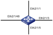
Figure 1-1 Network diagram for protocol-based VLAN and IP subnet-based VLAN
III. Configuration procedure
# Configure an IP subnet-based VLAN.
<H3C> system-view
[H3C] vlan 10
[H3C-vlan10] ip-subnet-vlan ip 10.11.113.0 24
[H3C-vlan10] port ethernet 2/1/1
[H3C-vlan10] quit
# Configure a protocol-based VLAN.
[H3C] vlan 20
[H3C-vlan20] protocol-vlan ip
[H3C-vlan20] port ethernet 2/1/3
[H3C-vlan20] quit
# Configure an egress port.
[H3C] vlan 30
[H3C-vlan30] port ethernet 2/1/5
[H3C-vlan30] quit
# Configure an ingress port.
[H3C]interface ethernet 2/1/48
[H3C-Ethernet2/1/48] port link-type hybrid
[H3C-Ethernet2/1/48] port hybrid vlan 10 20 30 untagged
[H3C-Ethernet2/1/48] port hybrid pvid vlan 30
# Apply the protocol to a port.
[H3C-Ethernet2/1/48] port hybrid ip-subnet-vlan vlan 10
[H3C-Ethernet2/1/48] port hybrid protocol-vlan vlan 20 all
Chapter 2 Super VLAN Configuration
When configuring super VLAN, go to these sections for information you are interested in:
l Super VLAN Configuration Example
2.1 Super VLAN Overview
Super VLAN, also called VLAN aggregation, is a collection of sub VLANs, each being a distinct broadcast domains isolated at Layer 2. You can create a virtual interface with an IP address for a super VLAN but not for the sub VLANs in it. When users in a sub VLAN need to communicate with each other, they use the IP address of the virtual interface of the super VLAN as the IP address of the gateway. As the IP address is shared by all sub VLANs, IP addresses are saved. For different sub VLANs to communicate with one another at Layer 3, or for a sub VLAN to communicate with other networks, you can enable the proxy ARP (Address Resolution Protocol) function. The super VLAN can use proxy ARP to forward and process ARP requests and responses so that the isolated sub VLANs can communicate with each other at Layer 3. By default, proxy ARP is disabled in a sub VLAN.
2.2 Configuring a Super VLAN
Super VLAN configuration includes:
l Configure a VLAN to be a super VLAN
l Configure sub VLANs
l Establish mappings between the super VLAN and the sub VLANs
l Enable proxy ARP for the sub VLANs
& Note:
l You can configure multiple super VLANs for a switch. Configuring the VLAN interface and IP address for a super VLAN is the same as that for a common VLAN.
l Configuring sub VLANs is the same as configuring a common VLAN. This section only provides the configuration steps. For detailed information, refer to VLAN Configuration.
Follow these steps to configure a super VLAN:
|
To do… |
Use the command… |
Remarks |
|
Enter system view |
system-view |
— |
|
Enter VLAN view |
vlan vlan-id |
Required |
|
Set the VLAN type to super VLAN |
supervlan |
Required The VLAN-ID is the configured VLAN ID in the range 1 to 4094. |
|
Return to system view |
quit |
— |
|
Create a sub VLAN and enter sub VLAN view |
vlan vlan-id |
Required |
|
Add Ethernet ports to sub a VLAN |
port interface-list |
Optional |
|
Return to system view |
quit |
— |
|
Enter Super VLAN view |
vlan vlan-id |
— |
|
Configure the mapping between the super VLAN and the sub VLANs |
subvlan sub-vlan-list |
Required |
|
Enter sub VLAN view |
vlan vlan-id |
— |
|
Enable proxy ARP for the sub VLAN |
arp proxy enable |
Optional This command is necessary for multiple sub VLANs to communicate with one another. |
|
Display configuration information |
display super vlan [ supervlan-id ] |
Optional You can execute the display super vlan command in any view. |
![]() Caution:
Caution:
l A Super VLAN cannot contain ports.
l After you set the VLAN type to super VLAN, proxy ARP is automatically enabled on the VLAN interface.
l The default VLAN cannot be set to a super VLAN.
l You can add multiple ports (non-uplink ports) to a sub VLAN.
l You cannot configure a virtual VLAN interface for a sub VLAN.
l If no VLAN ID is specified in the undo subvlan command, the mappings between all sub VLANs and the specified super VLAN is removed; if VLAN ID(s) are specified, only the mappings between the specified sub VLANs and the specified super VLAN is removed.
l In a super VLAN, do not enable multicast VLAN and IGMP-snooping.
l Super VLAN does not support VRRP.
2.3 Super VLAN Configuration Example
I. Network requirements
Create Super VLAN 10.
Create sub VLANs VLAN 2, VLAN 3 and VLAN 5.
l VLAN 2 contains ports Ethernet 3/1/1 and Ethernet 3/1/2.
l VLAN 3 contains ports Ethernet 3/1/3 and Ethernet 3/1/4.
l VLAN 5 contains ports Ethernet 3/1/5 and Ethernet 3/1/6.
Configure the Super VLAN so that these sub VLANs are isolated at Layer 2 but can communicate with one another at Layer 3.
II. Network diagram
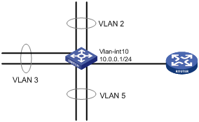
Figure 2-1 Network diagram for Super VLAN configuration
III. Configuration procedure
<H3C>system-view
System View: return to User View with Ctrl+Z.
[H3C] vlan 10
[H3C-vlan10] supervlan
[H3C-vlan10] vlan 2
[H3C-vlan2] port ethernet3/1/1 ethernet3/1/2
[H3C-vlan2] arp proxy enable
[H3C-vlan2] vlan 3
[H3C-vlan3] port ethernet3/1/3 ethernet3/1/4
[H3C-vlan3] arp proxy enable
[H3C-vlan3] vlan 5
[H3C-vlan5] port ethernet3/1/5 ethernet3/1/6
[H3C-vlan5] arp proxy enable
[H3C-vlan5] vlan 10
[H3C-vlan10] subvlan 2 3 5
[H3C-vlan10] interface vlan-interface 10
[H3C-Vlan-interface10] ip address 10.110.1.1 255.255.255.0
[H3C-Vlan-interface10] quit
Chapter 3 Isolate-User-VLAN Configuration
When configuring an isolate-user-VLAN, go to these sections for information you are interested in:
l Configuring an Isolate-User-VLAN
l Displaying and Maintaining Isolate-User-VLANs
l Isolate-User-VLAN Configuration Example
3.1 Isolate-User-VLAN Overview
An isolate-user-VLAN adopts a two-tier VLAN structure. In this approach, two types of VLANs, isolate-user-VLAN and secondary VLAN, are configured on the same device.
The following are the characteristics of the isolate-user-VLAN implementation:
l Isolate-user-VLANs are mainly used for upstream data exchange. An isolate-user-VLAN can be associated with multiple secondary VLANs. As the upstream device is aware of only the isolate-user-VLAN but not the secondary VLANs, network configuration is simplified and VLAN resources are saved.
l You can isolate the Layer 2 traffic of different users by assigning the ports connected to them to different secondary VLANs. To enable communication between secondary VLANs associated with the same isolate-user-VLAN, you can enable local proxy ARP on the upstream device to realize Layer 3 communication between the secondary VLANs.
As illustrated in the following figure, the isolate-user-VLAN function is enabled on Switch B. VLAN 10 is the isolate-user-VLAN, and VLAN 2, VLAN 5, and VLAN 8 are secondary VLANs associated with VLAN 10 and are invisible to Switch A.
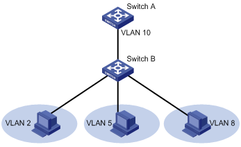
Figure 3-1 An isolate-user-VLAN example
3.2 Configuring an Isolate-User-VLAN
3.2.1 Configuration Task List
Complete these tasks to configure an isolate-user-VLAN:
|
Task |
Remarks |
|
Required |
|
|
Required |
|
|
Required |
3.2.2 Configuring an Isolate-User-VLAN
Follow these steps to configure an isolate-user-VLAN:
|
To do… |
Use the command… |
Remarks |
|
Enter system view |
system-view |
— |
|
Create a VLAN |
vlan vlan-id |
Required |
|
Configure the VLAN as an isolate-user-VLAN |
isolate-user-vlan enable |
Required You cannot configure VLAN 1 as an isolate-user-VLAN. |
|
Assign ports to the isolate-user-VLAN |
port interface-list |
Optional An isolate-user-VLAN can contain multiple ports, including the uplink port connected to the upstream switch. The member ports can be access or hybrid ports but not trunk ports. |
3.2.3 Configuring a Secondary VLAN
Follow these steps to configure a secondary VLAN:
|
To do… |
Use the command… |
Remarks |
|
Enter system view |
system-view |
— |
|
Create a VLAN |
vlan vlan-id |
Required You cannot configure VLAN 1 as a secondary VLAN. |
|
Assign ports to the secondary VLAN |
port interface-list |
Optional You can assign multiple ports to a secondary VLAN, excluding the uplink port. |
Follow the same procedure to configure multiple secondary VLANs.
& Note:
l You can associate an isolate-user-VLAN with up to 64 secondary VLANs.
l You can configure up to 32 isolate-user-VLANs.
l You can configure up to 1,024 secondary VLANs.
l You cannot configure the same MAC address in the secondary VLANs associated with the same isolate-user-VLAN.
l You cannot configure a VLAN interface for an isolate-user-VLAN or secondary VLAN; neither can you configure a VLAN with a VLAN interface as an isolate-user-VLAN or secondary VLAN.
3.2.4 Mapping an Isolate-User-VLAN to Secondary VLANs
Follow these steps to map an isolate-user-VLAN with secondary VLANs:
|
To do… |
Use the command… |
Remarks |
|
Enter system view |
system-view |
— |
|
Map an isolate-user-VLAN to secondary VLANs |
isolate-user-vlan isolate-user-vlan-num secondary secondary-vlan-numlist |
Required |
I. Guidelines on mapping an isolate-user-VLAN to secondary VLANs
Note the following when mapping an isolate-user-VLAN to secondary VLANs:
1) If the isolate-user-VLAN contains ports
l As for hybrid ports assigned to the isolate-user-VLAN in untagged mode and configured with the default VLAN ID the same as the isolate-user-VLAN ID, the switch synchronizes their configurations and assigns them to the secondary VLANs in untagged mode. Other hybrid ports will not be assigned to the secondary VLANs.
l As for access ports, the switch synchronizes their configurations and assigns them as hybrid ports in untagged mode to the isolate-user-VLAN and the secondary VLANs and use the isolate-user-VLAN ID as their default VLAN ID.
2) If a secondary VLAN contains ports
l As for hybrid ports assigned to the secondary VLAN in untagged mode and configured with the default VLAN ID the same as the isolate-user-VLAN ID, the switch synchronizes their configurations and assigns them to the isolate-user-VLAN in untagged mode. Other hybrid ports will not be assigned to the isolate-user-VLAN.
l As for access ports, the switch synchronizes their configurations and assigns them as hybrid ports in untagged mode to the isolate-user-VLAN and the secondary VLANs and use the secondary VLAN IDs as their default VLAN IDs.
II. Guidelines on isolate-user-VLAN configuration after an isolate-user-VLAN is mapped to a secondary VLAN
Note the following after mapping an isolate-user-VLAN with a secondary VLAN:
l You cannot assign access ports to the isolate-user-VLAN or the secondary VLAN.
l You can assign (remove) hybrid ports to (from) the isolate-user-VLAN or the secondary VLAN, but the switch does not synchronize the configurations of hybrid ports assigned to the secondary VLAN or isolate-user-VLAN after the mapping between the VLANs is established.
& Note:
l You cannot configure an isolate-user-VLAN or secondary VLAN as a VLAN of any other type, such as a multicast VLAN, Super/sub VLAN, guest VLAN or VLAN that carries the L2VPN service.
l An isolate-user-VLAN or secondary VLAN cannot contain trunk ports.
3.3 Displaying and Maintaining Isolate-User-VLANs
|
To do… |
Use the command… |
Remarks |
|
Display mappings between isolate-user-VLANs and secondary VLANs |
display isolate-user-vlan [ isolate-user-vlan-num ] |
Available in any view |
3.4 Isolate-User-VLAN Configuration Example
I. Network requirements
Switch A is connected to Switch B and Switch C at the downstream.
1) On Switch B
VLAN 5 is an isolate-user-VLAN, containing an uplink port (Ethernet 2/1/1) and two secondary VLANs, VLAN 2 and VLAN 3. VLAN 2 contains port Ethernet 2/1/2 and VLAN 3 contains port Ethernet 2/1/3.
2) On Switch C
VLAN 6 is an isolate-user-VLAN, containing an uplink port (Ethernet 2/1/1) and two secondary VLANs, VLAN 3 and VLAN 4. VLAN 3 contains port Ethernet 2/1/3 and VLAN 4 contains port Ethernet2/1/4.
Seen from Switch A, Switch B and Switch C each carry only one VLAN, VLAN 5 and VLAN 6 respectively.
II. Network diagram
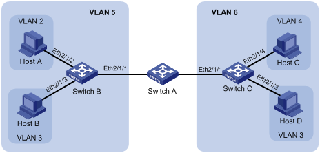
Figure 3-2 Network diagram for isolate-user-VLAN configuration
III. Configuration procedure
Only the configurations on Switch B and Switch C are provided.
1) Configuration on Switch B
# Configure the isolate-user-VLAN.
<H3C> system-view
[H3C] vlan 5
[H3C-vlan5] isolate-user-vlan enable
[H3C-vlan5] port ethernet2/1/1
# Configure the secondary VLANs.
[H3C-vlan5] vlan 3
[H3C-vlan3] port ethernet2/1/3
[H3C-vlan3] vlan 2
[H3C-vlan2] port ethernet2/1/2
# Configure the mapping between the isolate-user-VLAN and the secondary VLANs.
[H3C-vlan2] quit
[H3C] isolate-user-vlan 5 secondary 2 to 3
2) Configuration on Switch C
# Configure the isolate-user-VLAN.
<H3C> system-view
[H3C] vlan 6
[H3C-vlan6] isolate-user-vlan enable
[H3C-vlan6] port ethernet2/1/1
# Configure the secondary VLANs.
[H3C-vlan6] vlan 3
[H3C-vlan3] port ethernet2/1/3
[H3C-vlan3] vlan 4
[H3C-vlan4] port ethernet2/1/4
# Configure the mapping between the isolate-user-VLAN and the secondary VLANs.
[H3C-vlan4] quit
[H3C] isolate-user-vlan 6 secondary 3 to 4