- Table of Contents
- Related Documents
-
| Title | Size | Download |
|---|---|---|
| 07-Radio Configuration | 463.16 KB |
Configuring data transmit rates
Configuring 802.11a/802.11b/802.11g rates
Channel calibration information
Configuring channel scanning parameters
Configuring the detection record aging time
The interface types and output information vary by device model and radio type.
RF refers to electrical signals that can be transferred over the space to a long distance. 802.11b/g in the IEEE 802.11 standards operates at the 2.4 GHz band, 802.11a/ac operates at the 5 GHz band, and 802.11n operates at both the 2.4 GHz and 5 GHz bands. Radio frequency is allocated in bands, each of which corresponds to a range of frequencies.
Configuring radio parameters
Before configuring a radio, disable the radio.
To configure radio parameters:
Select Radio > Radio from the navigation tree.
Select the desired radio, and click the ![]() icon
to enter the page for AP radio setup page.
icon
to enter the page for AP radio setup page.

Configure the radio as described in Table 1.
|
Item |
Description |
|
Radio Unit |
Selected AP's radios. |
|
Radio Mode |
Radio mode. If you change the selected AP's radio mode, the transmit power and working channel of the AP are restored to the default of the corresponding mode. |
|
Transmit Power |
Maximum radio transmission power, which varies with country codes, channels, AP models, radio modes and antenna types. If you adopt the 802.11n mode, the maximum transmit power of the radio also depends on the bandwidth mode. |
|
Channel |
Working channel of the radio, which varies with radio types and country codes. auto: The working channel is automatically selected. If you select this mode, the AP checks the channel quality in the WLAN network, and selects the channel of the best quality as its working channel. If you modify the working channel configuration, the transmit power is automatically adjusted. |
|
Antenna Gain |
Configure the gain for the third-party antenna. |
|
802.11n |
The option is visible only when you select an AP supporting 802.11n and the radio mode is 802.11n. |
|
802.11ac |
802.11ac parameters are available only when the AP supports 802.11ac and the radio mode 802.11ac is selected. |
|
Bandwidth Mode |
802.11n can bond two adjacent 20-MHz channels together to form a 40-MHz channel. During data forwarding, the two 20-MHz channels can work separately with one acting as the primary channel and the other acting as the secondary channel. This provides a simple way of doubling the data rate. By default, the channel bandwidth of the 802.11n radio (5 GHz) is 40 MHz, and that of the 802.11n radio (2.4 GHz) is 20 MHz. 802.11ac bonds four adjacent 20-MHz channels together to form an 80 MHz channel, which increases the bandwidth and throughput. Like 802.11n, 802.11ac also ensures the throughput by increasing the channel usage rate. 802.11ac only supports 5 GHz. By default, the channel bandwidth of 802.11ac radios is 80 MHz.
· If the channel bandwidth of the radio is set to 40 MHz, a 40 MHz channel is used as the working channel. If no 40 MHz channel is available, a 20 MHz channel is used. For the specifications, see IEEE 802.11n-2009. · If the channel bandwidth of the radio is set to 80 MHz, an 80 MHz channel is used as the working channel when the corresponding center frequency is found. If no corresponding center frequency is found, the device attempts to use a 40 MHz channel. The 40 MHz channel is used if a channel that can be bound is found. If the device cannot find a channel that can be bound, it uses a 20 MHz channel. For the specifications, see IEEE P802.11acTM/D5.0. · If you modify the bandwidth mode configuration, the transmit power is automatically refreshed. |
|
MIMO |
Configure the MIMO mode for a radio: · default—No MIMO mode is set. · 1x1—Enable a radio to transmit and receive 1 space stream at a time. · 2x2—Enable a radio to transmit and receive 2 space streams at a time. · 3x3—Enable a radio to transmit and receive 3 space streams at a time. MIMO is applicable only to 802.11n and 802.11ac radios that support a minimum of two space streams. NOTE: Only the WA4620i-ACN and WA4620E-ACN fat APs support the 3x3 mode. |
|
Auto-switch |
Select this option to allow automatic bandwidth switch. If the channel bandwidth of an 802.11gn radio is 40 MHz, the automatic bandwidth switch function is not enabled by default. NOTE: Only 802.11gn radios support this option. |
|
Access Type |
Select the client type that is allowed to associate with the radio. · all type—The radio allows 802.11a/an/ac clients to associate with it. · 802.11n and 802.11ac—The radio allows 802.11n/ac clients to associate with it. · 802.11ac—The radio allows 802.11ac clients to associate with it. By default, an 802.11ac radio allows 802.11a/11an/ac clients to associate with it. Only 802.11ac radios support this option. For the 802.11n and 802.11ac or 802.11ac client type configuration to take effect, you must configure 802.11ac NSS. For more information about 802.11ac NSS, see "Configuring 802.11ac rates." |
|
Green Energy Management |
Select this option to enable energy saving. By default, this function is disabled. Only 802.11n and 802.11ac radios support this option. |
|
Client 802.11n Only |
If you select the Client 802.11n Only option, only 802.11n clients are allowed to access. To provide access for all 802.11a/b/g clients, disable this function.
To allow only 802.11n clients to access the network, configure mandatory MCS. For the configuration of mandatory MCS, see "Configuring 802.11n rates." |
|
A-MSDU |
Select the A-MSDU option to enable A-MSDU. MSDUs can be aggregated into a single A-MSDU. This reduces the MAC header overhead and thus improves MAC layer forwarding efficiency. |
|
A-MPDU |
Select the A-MPDU option to enable A-MPDU. 802.11n introduces the Aggregated MAC Protocol Data Unit (A-MPDU) frame format. By using only one PHY header, each A-MPDU can accommodate multiple MPDUs that have their PHY headers removed. This reduces the overhead in transmission and the number of ACK frames to be used, and thus improves network throughput. |
|
Short GI |
Select the Short GI option to enable short GI. The 802.11a/g GI is 800 ns. You can configure a short GI (400 ns) for 802.11n or 802.11ac. It increases the throughput by 10 percent. |
Expand Advanced Setup.
Figure 2 Configuring advanced radio settings
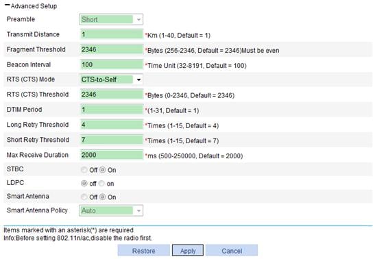
Configure the radio as described in Table 2.
Click Apply.
|
Item |
Description |
|
Preamble |
Preamble is a pattern of bits at the beginning of a frame so that the receiver can sync up and be ready for the real data. There are two different kinds of preambles: · Short preamble—A short preamble improves network performance. Therefore, this option is always selected. · Long preamble—A long preamble ensures compatibility between access point and some legacy client devices. Therefore, you can select this option to make legacy client devices support short preamble. 802.11a/802.11n (5 GHz)/802.11ac(5GHz) does not support this configuration. |
|
Transmit Distance |
Maximum transmission distance. |
|
Fragment Threshold |
Specify the maximum length of frames that can be transmitted without fragmentation. When the length of a frame exceeds the specified fragment threshold value, it is fragmented. · In a wireless network where error rate is high, you can decrease the fragment threshold by a rational value. In this way, when a fragment of a frame is not received, only this fragment rather than the whole frame needs to be retransmitted, and the throughput of the wireless network is improved. · In a wireless network where no collision occurs, you can increase the fragment threshold by a rational value to decrease acknowledgement packets and increase network throughput. Disable WMM before you configure the fragment threshold. |
|
Beacon Interval |
Interval for sending beacon frames. Beacon frames are transmitted at a regular interval to allow mobile clients to join the network. Beacon frames are used for a client to identify nearby APs or network control devices. |
|
RTS (CTS) |
There are two data collision avoidance mechanisms, RTS/CTS and CTS-to-self. · RTS/CTS—In this mode, an AP sends an RTS packet before sending data to a client. After receiving the RTS packet, all the devices within the coverage of the AP will not send data within the specified time. Upon receiving the RTS packet, the client sends a CTS packet, ensuring that all the devices within the coverage of the client will not send data within the specified time. The RTS/CTS mechanism requires two frames to implement data collision avoidance, and thus has a higher cost. · CTS-to-Self—In this mode, an AP uses its IP address to send a CTS packet before sending data to a client, ensuring that all the devices within the coverage of the AP do not send data within the specified time. The CTS-to-Self mechanism uses only one frame to avoid data collision. However, if another device is in the coverage of the client, but not in the coverage of the AP, data collision still may occur. Compared with RTS/CTS, CTS-to-Self reduces the number of control frames. However, data collisions still occur when some clients are hidden and thus cannot receive the CTS frames sent by the AP. Therefore, the RTS/CTS mechanism can solve the data collision problem in a larger coverage than RTS/CTS. |
|
RTS (CTS) Threshold |
If a frame is larger than the RTS (CTS) threshold, the data collision avoidance mechanism will be used. A smaller RTS/CTS threshold causes RTS/CTS packets to be sent more often, consuming more bandwidth. However, the more often RTS/CTS packets are sent, the quicker the system can recover from collisions. In a high-density WLAN, you can decrease the RTS threshold to reduce collisions in the network.
The data collision avoidance mechanism occupies bandwidth. Therefore, this mechanism applies only to data frames larger than the RTS/CTS threshold. |
|
DTIM Period |
Number of beacon intervals between delivery traffic indication message (DTIM) transmissions. The AP sends buffered broadcast/multicast frames when the DTIM counter reaches 0. |
|
Long Retry Threshold |
Number of retransmission attempts for unicast frames larger than the RTS/CTS threshold. |
|
Short Retry Threshold |
Number of retransmission attempts for unicast frames smaller than the RTS/CTS threshold if no acknowledgment is received for it. |
|
Max Receive Duration |
Interval for which a frame received by an AP can stay in the buffer memory. |
|
STBC |
· On—Enable STBC. · Off—Disable STBC. By default, STBC is enabled. Enabling STBC improves the SNR of the receiver and data transmission reliability. STBC can be used for wireless access and mesh/WDS links. When you enable STBC on a mesh/WDS link, H3C recommends that you enable STBC on both the sender and receiver to get best performance. STBC takes effect only when the number of antennas on an AP is greater than the number of spatial streams corresponding to the rates used by the radio. |
|
LDPC |
· On—Enable LDPC. · Off—Disable LDPC. By default, Low Density Parity Check Code (LDPC) is disabled. |
|
Smart Antenna |
· On—Enable the smart antenna function. · Off—Disable the smart antenna function. By default, the smart antenna function is enabled. This function takes effect only when you select a built-in antenna for the radio. To select a built-in antenna, select Radio > Antenna from the navigation tree. Enabling this function makes sure clients in the coverage of the AP can get a higher and stable bandwidth. In addition, this function reduces interference between APs and clients and avoids interference from non wireless devices in a high-density wireless network. This option is available only for devices that support smart antenna. |
|
Smart Antenna Policy |
· Auto—Use the auto policy, which means the high-reliability policy is used for voice and video frames and the high-throughput policy is used for other frames. · High Reliability—Use the high reliability policy. · High Throughput—Use the high throughput policy. By default, a smart antenna uses the auto policy. The configuration takes effect only when the smart antenna function is enabled. |
Configuring data transmit rates
Configuring 802.11a/802.11b/802.11g rates
Select Radio > Rate from the navigation tree to enter the rate setting page.
Figure 3 Setting 802.11a/802.11b/802.11g rates

Configure 802.11a/802.11b/802.11g rates as described in Table 3.
Click Apply.
|
Item |
Description |
|
802.11a |
Configure rates (in Mbps) for 802.11a. By default: · Mandatory rates—6, 12, and 24. · Supported rates—9, 18, 36, 48, and 54. · Multicast rate—Automatically selected from the mandatory rates. The transmission rate of multicasts in a BSS is selected from the mandatory rates supported by all the clients. |
|
802.11b |
Configure rates (in Mbps) for 802.11b. By default: · Mandatory rates—1 and 2. · Supported rates—5.5 and 11. · Multicast rate—Automatically selected from the mandatory rates. The transmission rate of multicasts in a BSS is selected from the mandatory rates supported by all the clients. |
|
802.11g |
Configure rates (in Mbps) for 802.11g. By default: · Mandatory rates—1, 2, 5.5, and 11. · Supported rates—6, 9, 12, 18, 24, 36, 48, and 54. · Multicast rate—Automatically selected from the mandatory rates. The transmission rate of multicasts in a BSS is selected from the mandatory rates supported by all the clients. |
Configuring 802.11n rates
Introduction to MCS
Configuration of mandatory and supported 802.11n rates is achieved by specifying the maximum Modulation and Coding Scheme (MCS) index. The MCS data rate table shows relations between data rates, MCS indexes, and parameters that affect data rates. Sample MCS data rate tables for 20 MHz and 40 MHz are shown in Table 4 and Table 5. For the whole table, see IEEE P802.11n D2.00.
Table 4 and Table 5 indicate that MCS 0 through 7 are for one single spatial stream, and when the MCS is 7, the data rate is the highest; MCS 8 through 15 are for two spatial streams, and when the MCS is 15, the data rate is the highest. MCS 16 through 23 are for three spatial streams, and when the MCS is 23, the data rate is the highest. For the whole table, see IEEE 802.11n-2009.
Table 4 MCS index table (20 MHz)
|
MCS index |
Number of spatial streams |
Modulation |
Data rate (Mbps) |
|||
|
800ns GI |
400ns GI |
|||||
|
0 |
1 |
BPSK |
6.5 |
7.2 |
||
|
1 |
1 |
QPSK |
13.0 |
14.4 |
||
|
2 |
1 |
QPSK |
19.5 |
21.7 |
||
|
3 |
1 |
16-QAM |
26.0 |
28.9 |
||
|
4 |
1 |
16-QAM |
39.0 |
43.3 |
||
|
5 |
1 |
64-QAM |
52.0 |
57.8 |
||
|
6 |
1 |
64-QAM |
58.5 |
65.0 |
||
|
7 |
1 |
64-QAM |
65.0 |
72.2 |
||
|
8 |
2 |
BPSK |
13.0 |
14.4 |
||
|
9 |
2 |
QPSK |
26.0 |
28.9 |
||
|
10 |
2 |
QPSK |
39.0 |
43.3 |
||
|
11 |
2 |
16-QAM |
52.0 |
57.8 |
||
|
12 |
2 |
16-QAM |
78.0 |
86.7 |
||
|
13 |
2 |
64-QAM |
104.0 |
115.6 |
||
|
14 |
2 |
64-QAM |
117.0 |
130.0 |
||
|
15 |
2 |
64-QAM |
130.0 |
144.4 |
||
|
16 |
3 |
BPSK |
19.5 |
21.7 |
||
|
17 |
3 |
QPSK |
39.0 |
43.3 |
||
|
18 |
3 |
QPSK |
58.5 |
65.0 |
||
|
19 |
3 |
16-QAM |
78.0 |
86.7 |
||
|
20 |
3 |
16-QAM |
117.0 |
130.0 |
||
|
21 |
3 |
64-QAM |
156.0 |
173.3 |
||
|
22 |
3 |
64-QAM |
175.5 |
195.0 |
||
|
23 |
3 |
64-QAM |
195.0 |
216.7 |
||
Table 5 MCS index table (40 MHz)
|
MCS index |
Number of spatial streams |
Modulation |
Data rate (Mbps) |
|
||
|
800ns GI |
400ns GI |
|
||||
|
0 |
1 |
BPSK |
13.5 |
15.0 |
|
|
|
1 |
1 |
QPSK |
27.0 |
30.0 |
|
|
|
2 |
1 |
QPSK |
40.5 |
45.0 |
|
|
|
3 |
1 |
16-QAM |
54.0 |
60.0 |
|
|
|
4 |
1 |
16-QAM |
81.0 |
90.0 |
|
|
|
5 |
1 |
64-QAM |
108.0 |
120.0 |
|
|
|
6 |
1 |
64-QAM |
121.5 |
135.0 |
|
|
|
7 |
1 |
64-QAM |
135.0 |
150.0 |
|
|
|
8 |
2 |
BPSK |
27.0 |
30.0 |
|
|
|
9 |
2 |
QPSK |
54.0 |
60.0 |
|
|
|
10 |
2 |
QPSK |
81.0 |
90.0 |
|
|
|
11 |
2 |
16-QAM |
108.0 |
120.0 |
|
|
|
12 |
2 |
16-QAM |
162.0 |
180.0 |
|
|
|
13 |
2 |
64-QAM |
216.0 |
240.0 |
|
|
|
14 |
2 |
64-QAM |
243.0 |
270.0 |
|
|
|
15 |
2 |
64-QAM |
270.0 |
300.0 |
|
|
|
16 |
3 |
BPSK |
40.5 |
45 |
||
|
17 |
3 |
QPSK |
81.0 |
90.0 |
||
|
18 |
3 |
QPSK |
121.5 |
135.0 |
||
|
19 |
3 |
16-QAM |
162.0 |
180.0 |
||
|
20 |
3 |
16-QAM |
243.0 |
270.0 |
||
|
21 |
3 |
64-QAM |
324.0 |
360.0 |
||
|
22 |
3 |
64-QAM |
364.5 |
405.0 |
||
|
23 |
3 |
64-QAM |
405.0 |
450.0 |
||
For example, if you specify the maximum MCS index as 5 for mandatory rates, rates corresponding to MCS indexes 0 through 5 are configured as 802.11n mandatory rates.
· Mandatory rates must be supported by the AP and the clients that want to associate with the 802.11n AP.
· Supported rates allow some clients that support both mandatory and supported rates to choose higher rates when communicating with the AP.
· Multicast MCS: Specifies 802.11n multicast data rates.
Configuring 802.11n rates
Select Radio > Rate from the navigation tree to enter the rate setting page.
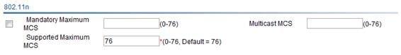
Configure 802.11n rates as described in Table 6.
Click Apply.
|
Item |
Description |
|
Mandatory Maximum MCS |
Set the maximum MCS index for 802.11n mandatory rates. |
|
Multicast MCS |
Set the multicast MCS for 802.11n. The multicast MCS is adopted only when all the clients use 802.11n. If a non 802.11n client exists, multicast traffic is transmitted at a mandatory MCS data rate.
· If you configure a multicast MCS index greater than the maximum MCS index supported by the radio, the maximum MCS index is adopted. · When the multicast MCS takes effect, the corresponding data rates defined for 20MHz with SGI disabled are adopted no matter whether the 802.11n radio operates in 40 MHz mode or in 20 MHz mode. |
|
Supported Maximum MCS |
Set the maximum MCS index for 802.11n supported rates. The supported maximum MCS cannot be smaller than the mandatory maximum MCS. |
For more information about MCS, see WLAN Configuration Guide.
When 802.11n radios are used for WDS, make sure they have the same MCS configuration.
Configuring 802.11ac rates
Introduction to MCS
Configuration of 802.11ac radio rate is achieved by specifying the number of spatial streams (NSS). 802.11 ac uses very high throughput modulation and coding scheme (VHT-MCS) to indicate WLAN data rates. A VHT-MCS data rate table shows relations between data rates, VHT-MCS indexes, and parameters that affect data rates. In 802.11ac, the physical transmission rate upon specific parameters corresponding to the VHT-MCS index is determined by the VHT-MCS data rate table and NSS. Sample VHT-MCS data rate tables for 20 MHz, 40 MHz, and 80 MHz are shown in Table 7, Table 8, and Table 9, respectively. For the entire table, see IEEE Draft P802.11ac_D5.0.
The value range for NSS is 1 to 8, and the value range for VHT-MCS index in each NSS is 0 to 9.
Table 7 VHT-MCS data rate table (20 MHz, NSS=1)
|
VHT-MCS index |
Modulation |
Data rate (Mbps) |
|
|
800ns GI |
400ns GI |
||
|
0 |
BPSK |
6.5 |
7.2 |
|
1 |
QPSK |
13.0 |
14.4 |
|
2 |
QPSK |
19.5 |
21.7 |
|
3 |
16-QAM |
26.0 |
28.9 |
|
4 |
16-QAM |
39.0 |
43.3 |
|
5 |
64-QAM |
52.0 |
57.8 |
|
6 |
64-QAM |
58.5 |
65.0 |
|
7 |
64-QAM |
65.0 |
72.2 |
|
8 |
256-QAM |
78.0 |
86.7 |
|
9 |
not valid |
||
Table 8 VHT-MCS data rate table (40 MHz, NSS=1)
|
VHT-MCS index |
Modulation |
Data rate (Mbps) |
|
|
800ns GI |
400ns GI |
||
|
0 |
BPSK |
13.5 |
15.0 |
|
1 |
QPSK |
27.0 |
30.0 |
|
2 |
QPSK |
40.5 |
45.0 |
|
3 |
16-QAM |
54.0 |
60.0 |
|
4 |
16-QAM |
81.0 |
90.0 |
|
5 |
64-QAM |
108.0 |
120.0 |
|
6 |
64-QAM |
121.5 |
135.0 |
|
7 |
64-QAM |
135.0 |
150.0 |
|
8 |
256-QAM |
162.0 |
180.0 |
|
9 |
256-QAM |
180.0 |
200.0 |
Table 9 VHT-MCS data rate table (80 MHz, NSS=1)
|
VHT-MCS index |
Modulation |
Data rate (Mbps) |
|
|
800ns GI |
400ns GI |
||
|
0 |
BPSK |
29.3 |
32.5 |
|
1 |
QPSK |
58.5 |
65.0 |
|
2 |
QPSK |
87.8 |
97.5 |
|
3 |
16-QAM |
117.0 |
130.0 |
|
4 |
16-QAM |
175.5 |
195.0 |
|
5 |
64-QAM |
234.0 |
260.0 |
|
6 |
64-QAM |
263.3 |
292.5 |
|
7 |
64-QAM |
292.5 |
325.0 |
|
8 |
256-QAM |
351.0 |
390.0 |
|
9 |
256-QAM |
390.0 |
433.3 |
NSS is divided into the following types:
· Mandatory NSS—Mandatory NSS must be supported by the AP and the clients that want to associate with the 802.11ac AP.
· Supported NSS—Supported NSS allows some clients that support both mandatory NSS and supported NSS to choose higher rates when communicating with the AP.
· Multicast NSS—Multicast NSS allows some clients and APs that support both mandatory NSS and multicast NSS to transmit multicast data with configured multicast NSS.
The NSS value refers to a value range, starting from 0 and ending with the configured value. For example, if you enter 5, the value range for NSS is 0 to 5.
When configuring multicast rate for 802.11ac radios, specify the multicast NSS and multicast VHT-MCS.
Configuring 802.11ac rates
Select Radio > Rate from the navigation tree.
Figure 5 Configuring 802.11ac rates

Configure the 802.11ac rate, and click Apply.
Configuring calibration
Channel calibration information
Select Radio > Calibration, from the navigation tree to enter the Operation tab.
Click a target radio to view the channel switching information of the radio.
Figure 6 Setting channel calibration

Table 10 Field description
|
Field |
Description |
|
NO |
Sequence number of channel switching. |
|
Chl(After/Before) |
Channels, before and after channel optimization. |
|
Date(yyyy-mm-dd) |
Channel switching date, in the format of yyyy-mm-dd. |
|
Time(hh:mm:ss) |
Channel switching time, in the format of hh:mm:ss. |
Setting parameters
Select Radio > Calibration from the navigation tree.
Click the Parameters tab to enter the page for setting parameters.

Configure channel calibration parameters as described in Table 11.
Click Apply.
|
Item |
Description |
|
802.11g Protection |
Because 802.11b and 802.11g use different modulation modes, 802.11g protection needs to be enabled for an 802.11g device to send RTS/CTS or CTS-to-self packets to 802.11b devices, which will defer access to the medium. · Enable—Enable 802.11g protection. · Close—Disable 802.11g protection. An AP running 802.11g uses the 802.11g protection function in the following two cases: · An 802.11b client is associated with it. · It detects APs or clients running 802.11b on the same channel.
· Enabling 802.11g protection reduces network performance. · Enabling 802.11g protection applies to the second case only because 802.11g protection is always enabled for the first case. |
|
802.11g Protection Mode |
· RTS/CTS—Use RTS/CTS mode to implement 802.11g protection. Before sending data to a client, an AP sends an RTS packet to the client, ensuring that all the devices within the coverage of the AP do not send data in the specified time after receiving the RTS packet. Upon receiving the RTS packet, the client sends a CTS packet, ensuring that all the devices within the coverage of the client do not send data in the specified time. · CTS-to-Self—Use CTS-to-Self mode to implement 802.11g protection. When an AP sends packets to a client, it uses its IP address to send a CTS packet to inform the client that it will send a packet, ensuring that all the devices within the coverage of the AP do not send data in the specified time. |
|
802.11n Protection Mode |
Both RTS/CTS and CTS-to-Self modes can be adopted. The implementation of the two modes is the same as 802.11g. |
|
802.11n Protection |
· Enable—Enable 802.11n protection. When non 802.11n wireless devices or non 802.11n clients exist within the coverage of the AP, you must enable 802.11n protection. · Close—Disable 802.11n protection. |
|
Spectrum Management |
· Enable—Enable spectrum management. · Close—Disable spectrum management. By default, spectrum management is disabled. After you enable spectrum management, the AP notifies its power capabilities and power constraint on clients. |
|
Power Constraint |
Enable the AP to notify all 802.11a clients to reduce their transmit power by a specified value. For example, if the power constraint is set to 5, the AP notifies 802.11a clients to decrease their maximum power by 5 dBm. By default, the transmit power for 802.11a radios is not restricted.
Before configuring the power constraint, enable spectrum management. Otherwise, the configuration does not take effect. |
Configuring channel scanning
Configuring channel scanning parameters
Select Radio > Channel Scan from the navigation tree to enter the Channel Scan tab.
Figure 8 Setting channel scanning
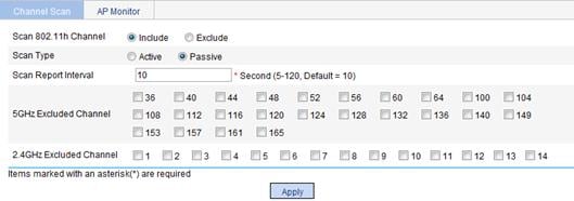
Configure channel scanning as described in Table 12.
Click Apply.
|
Item |
Description |
|
Scan 802.11h Channel |
Some 802.11h channels, called radar channels, overlap some 802.11a channels. If the device operates on an overlapping channel, its service quality may be affected. With this function enabled, the device selects a working channel from non-802.11h channels belonging to the configured country code to avoid channel collision. · Include—802.11h channels are included in initial channel scanning. · Exclude—802.11h channels are excluded in initial channel scanning. |
|
Scan Type |
Set the scanning type. For a client: · Active—Active scanning requires an AP to send probe requests to clients. This scanning mode enables an AP to discover surrounding devices more easily. · Passive—Passive scanning is used by an AP when it wants to save battery power. Typically, VoIP terminals adopt the passive scanning mode. The default scanning type is passive scanning. For an AP that has the monitoring function: · Active—The AP simulates a client to send probe requests during the scanning process. · Passive—The AP does not send probe requests during the scanning process. If you set active scanning for the AP, it is more likely to discover devices in the WLAN. |
|
Scan Interval |
Set the scan report interval. · A longer scan interval enables an AP to discover more devices in the WLAN. · A shorter scan interval enables an AP to send scanning reports to an AC more frequently. If an AP has the monitoring function, the scan report interval will affect whether the scanning results can be processed in time and the frequency of message exchanges. Therefore, you must set the interval properly according to the actual network conditions. |
|
5GHz Excluded Channel/2.4GHz Excluded Channel |
To avoid selecting improper channels, you can exclude specific channels from automatic channel selection. The excluded channels will not be available for initial automatic channel selection and DFS. This feature does not affect rogue detection and WIDS. Select a channel and add it to the 5GHz Excluded Channel or 2.4GHz Excluded Channel. By default, no channels exist in the 5GHz Excluded Channel or 2.4GHz Excluded Channel.
· The channel exclusion list is not restricted by the country code. You can add channels not supported by the country code to the list, and changing the country code does not change the channel list. The device will select an available channel from the channels supported by the country code and not in the channel exclusion list. When you configure this feature, do not add all channels supported by the country code to the channel exclusion list. · This feature takes effect only for initial automatic channel selection, DFS, and mesh DFS. · If you add an automatically selected channel into the channel exclusion list, the AP disables the radio, enables the radio, and then selects an available channel from the channels supported by the country code and not in the channel exclusion list. · If you add an automatically selected primary channel to the channel exclusion list, the AP will select another available primary channel. If you add a secondary channel into the channel exclusion list in this case, the AP will select another secondary channel. If the AP cannot find an available secondary channel, no channels will be available for the wireless services. |
Configuring AP operating mode
Overview
A fat AP can operate in one of the following modes:
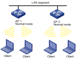
· Normal mode
As shown in Figure 9, when AP 1 and AP 2 operate in normal mode, they only provide WLAN services for clients.
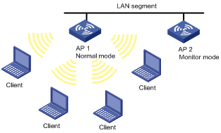
· Monitor mode
When AP 2 operates in monitor mode, it monitors all devices in the WLAN through scanning 802.11 frames and records scan results, but it does not provide WLAN services. As shown in Figure 10, set AP 2 to operate in monitor mode, and it will monitor all 802.11 frames. For more information about , see "Displaying detection record."
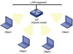
· Hybrid mode
When an AP operates in hybrid mode, it can both scan devices in the WLAN and act as a wireless access point, as shown in Figure 11.
An AP operating in monitor or hybrid mode monitors the WLAN. The administrator can monitor the WLAN by checking the monitoring records so as to adjust the WLAN settings when the interference is serious.
Configuring the operating mode of an AP
Select Radio > Channel Scan from the navigation tree.
Click the AP Monitor tab to enter the page for configuring AP operating mode.
Figure 12 Setting AP operating mode
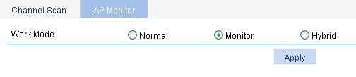
Configure the AP operating mode as described in Table 13.
Click Apply.
|
Item |
Description |
|
Work Mode |
Set the AP operating mode: · Normal—The AP only provides WLAN data services. · Monitor—The AP only scans all 802.11 frames in the WLAN. · Hybrid—The AP can both scan devices in the WLAN and provide WLAN data services.
· When an AP has its operating mode changed from normal or hybrid to monitor, it does not restart. · When an AP has its operating mode changed from monitor to normal or hybrid, it restarts. |
If an AP operates in hybrid mode, configure WLAN service so the AP can both scan devices in the WLAN and provide WLAN data services.
If an AP operates in monitor mode, the AP does not need to provide WLAN data services and you do not need to configure WLAN service.
Configuring channel detection
Displaying detection record
Select Radio > Channel Detection from the navigation tree to enter the Detect Record tab.
Figure 13 Displaying detection record

APs, wireless bridges, clients and ad hoc devices can be detected.
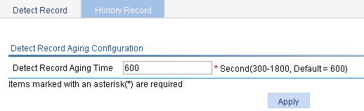
Configuring the detection record aging time
Select Radio > Channel Detection from the navigation tree.
Click the History Record tab to enter the history record page.
Enter the record aging time in the Detect Record Aging Time field.
Click Apply.
Figure 14 Configuring detection record aging time
Displaying history record
Select Radio > Channel Detection from the navigation tree.
Click the History Record tab to enter the history record page.
You can view the history record for channel scanning on the page.
Figure 15 Displaying history record
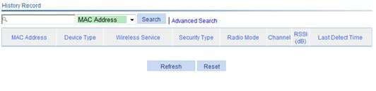
If an entry in the detection record is not refreshed within the aging time, it will be deleted from the detection record and added into the history record.
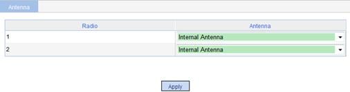
Selecting an antenna
Select Radio > Antenna from the navigation tree to select an appropriate antenna for the corresponding radio.
Select the antenna type for a specific radio from the Antenna list.
Click Apply.
Figure 16 Selecting an antenna