- Table of Contents
- Related Documents
-
| Title | Size | Download |
|---|---|---|
| 08-Authentication | 1.13 MB |
Recommended configuration procedure
Configuring authentication methods for the ISP domain
Configuring authorization methods for the ISP domain
Configuring accounting methods for the ISP domain
Recommended configuration procedure
Creating the HWTACACS scheme system
Configuring HWTACACS servers for the scheme
Configuring HWTACACS parameters for the scheme
HWTACACS configuration example
Configuring a guest by a common management-level user
Configuring a guest by a guest administrator
Recommended configuration procedures
Recommended configuration procedure for manual request
Recommended configuration procedure for automatic request
Retrieving and displaying a certificate
Requesting a local certificate
Retrieving and displaying a CRL
The AAA Web configuration interface provides the following configuration functions:
· Configuring an ISP domain
· Configuring authentication methods for the ISP domain
· Configuring authorization methods for the ISP domain
· Configuring accounting methods for the ISP domain
Overview
Authentication, Authorization, and Accounting (AAA) provides a uniform framework for implementing network access management. It provides the following security functions:
· Authentication—Identifies users and determines whether a user is valid.
· Authorization—Grants user rights and controls user access to resources and services. For example, a user who has successfully logged in to the device can be granted read and print permissions to the files on the device.
· Accounting—Records all network service usage information, including service type, start time, and traffic. The accounting function provides information required for charging, and allows for network security surveillance.
AAA can be implemented through multiple protocols. The device supports RADIUS and HWTACACS, of which RADIUS is most often used.
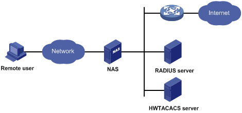
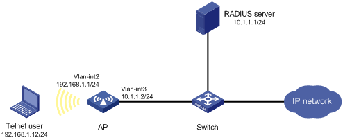
AAA typically uses a client/server model, as shown in Figure 1. The client runs on the network access server (NAS), which is also referred to as the access device. The server maintains user information centrally. In an AAA network, the NAS is a server for users but a client for AAA servers.
Figure 1 AAA application scenario
For more information about AAA, see Security Configuration Guide.
Configuration prerequisites
To deploy local authentication, configure local users on the access device. See "Configuring users."
To deploy RADIUS authentication, authorization, or accounting, create the RADIUS schemes to be referenced. See "Configuring RADIUS."
To deploy HWTACACS authentication, authorization, or accounting, create the HWTACACS schemes to be referenced. See "Configuring HWTACACS."
Recommended configuration procedure
|
Step |
Remarks |
|
Optional. Create ISP domains and specify one of them as the default ISP domain. By default, there is an ISP domain named system, which is the default ISP domain. |
|
|
Optional. Configure authentication methods for various types of users. By default, all types of users use local authentication. |
|
|
Optional. Specify the authorization methods for various types of users. |
|
|
Required. Specify the accounting methods for various types of users. By default, all types of users use local accounting. |
Configuring an ISP domain
1. Select Authentication > AAA from the navigation tree.
The Domain Setup page appears.
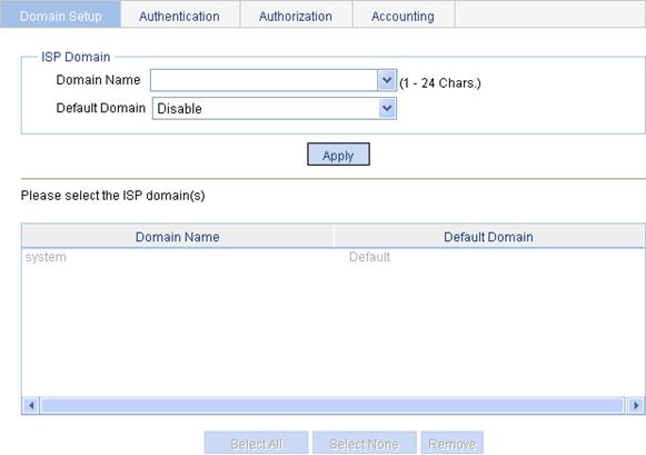
2. Configure an ISP domain, as described in Table 1.
3. Click Apply.
|
Item |
Description |
|
Domain Name |
Enter an ISP domain name for uniquely identifying the domain. You can enter a new domain name to create a domain, or specify an existing domain to change its status (whether it is the default domain). |
|
Default Domain |
Specify whether to use the ISP domain as the default domain. Options include: · Enable—Uses the domain as the default domain. · Disable—Uses the domain as a non-default domain. There can only be one default domain at a time. If you specify a second domain as the default domain, the original default domain will become a non-default domain. |
Configuring authentication methods for the ISP domain
1. Select Authentication > AAA from the navigation tree.
2. Click the Authentication tab to enter the authentication method configuration page.
Figure 3 Authentication method configuration page
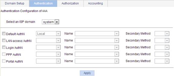
3. Configure authentication methods for various types of users in different ISP domains, as described in Table 2.
4. Click Apply.
A configuration progress dialog box appears.
5. After the configuration process is complete, click Close.
|
Item |
Description |
|
Select an ISP domain |
Select the ISP domain for which you want to specify authentication methods. |
|
Default AuthN Name Secondary Method |
Configure the default authentication method and secondary authentication method for all types of users. Options include: · HWTACACS—HWTACACS authentication. You must specify the HWTACACS scheme to be used. · Local—Local authentication. · None—No authentication. This method trusts all users and is not for general use. · RADIUS—RADIUS authentication. You must specify the RADIUS scheme to be used. · Not Set—The device uses the default authentication setting, which is local authentication. |
|
LAN-access AuthN Name Secondary Method |
Configure the authentication method and secondary authentication method for LAN access users. Options include: · Local—Local authentication. · None—No authentication. This method trusts all users and is not for general use. · RADIUS—RADIUS authentication. You must specify the RADIUS scheme to be used. · Not Set—The device uses the settings in the Default AuthN area for LAN access users. |
|
Login AuthN Name Secondary Method |
Configure the authentication method and secondary authentication method for login users. Options include: · HWTACACS—HWTACACS authentication. You must specify the HWTACACS scheme to be used. · Local—Local authentication. · None—No authentication. This method trusts all users and is not for general use. · RADIUS—RADIUS authentication. You must specify the RADIUS scheme to be used. · Not Set—The device uses the settings in the Default AuthN area for login users. |
|
PPP AuthN Name Secondary Method |
The device does not support the authentication method configuration for PPP users. |
|
Portal AuthN Name Secondary Method |
The device does not support the authentication method configuration for portal users. |
Configuring authorization methods for the ISP domain
1. Select Authentication > AAA from the navigation tree.
2. Click the Authorization tab to enter the authorization method configuration page.
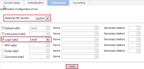
Figure 4 Authorization method configuration page
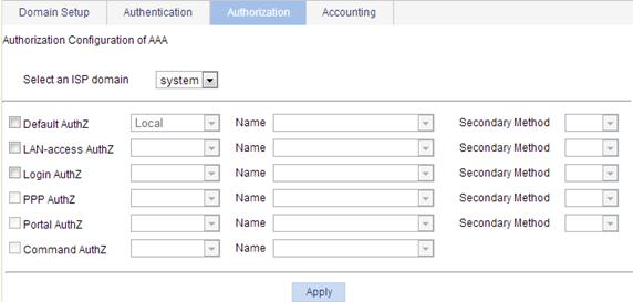
3. Configure authorization methods for various types of users in different ISP domains, as described in Table 3.
4. Click Apply.
A configuration progress dialog box appears.
5. After the configuration process is complete, click Close.
|
Item |
Description |
|
Select an ISP domain |
Select the ISP domain for which you want to specify authentication methods. |
|
Default AuthZ Name Secondary Method |
Configure the default authorization method and secondary authorization method for all types of users. Options include: · HWTACACS—HWTACACS authorization. You must specify the HWTACACS scheme to be used. · Local—Local authorization. · None—This method trusts all users and assigns default rights to them. · RADIUS—RADIUS authorization. You must specify the RADIUS scheme to be used. · Not Set—The device uses the default authorization setting, which is local authorization. |
|
LAN-access AuthZ Name Secondary Method |
Configure the authorization method and secondary authorization method for LAN access users. Options include: · Local—Local authorization. · None—This method trusts all users and assigns default rights to them. · RADIUS—RADIUS authorization. You must specify the RADIUS scheme to be used. · Not Set—The device uses the settings in the Default AuthZ area for LAN access users. |
|
Login AuthZ Name Secondary Method |
Configure the authorization method and secondary authorization method for login users. Options include: · HWTACACS—HWTACACS authorization. You must specify the HWTACACS scheme to be used. · Local—Local authorization. · None—This method trusts all users and assigns default rights to them. · RADIUS—RADIUS authorization. You must specify the RADIUS scheme to be used. · Not Set—The device uses the settings in the Default AuthZ area for login users. |
|
PPP AuthZ Name Secondary Method |
The device does not support the authorization method configuration for PPP users. |
|
Portal AuthZ Name Secondary Method |
The device does not support the authorization method configuration for portal users. |
|
Command AuthZ Name |
The device does not support the command authorization method. |
Configuring accounting methods for the ISP domain
1. Select Authentication > AAA from the navigation tree.
2. Click the Accounting tab to enter the accounting method configuration page.
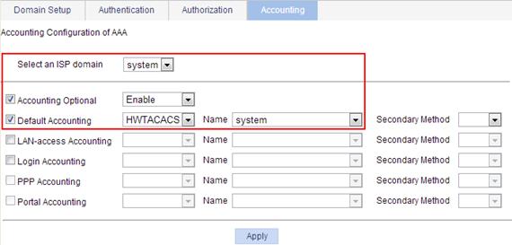
Figure 5 Accounting method configuration page
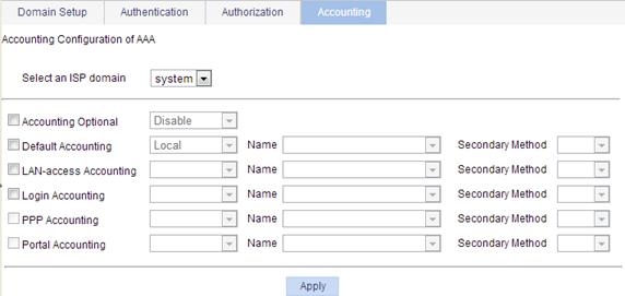
3. Configure accounting methods for various types of users in different ISP domains, as described in Table 4.
4. Click Apply.
A configuration progress dialog box appears.
5. After the configuration process is complete, click Close.
|
Item |
Description |
|
Select an ISP domain |
Select the ISP domain for which you want to specify authentication methods. |
|
Accounting Optional |
Specify whether to enable the accounting optional feature. The feature enables a user who would otherwise be disconnected to use network resources even if there is no accounting server available or communication with the current accounting server fails. If accounting for the user fails, the device no longer sends real-time accounting updates for the user. |
|
Default Accounting Name Secondary Method |
Configure the default accounting method and secondary accounting method for all types of users. Options include: · HWTACACS—HWTACACS accounting. You must specify the HWTACACS scheme to be used. · Local—Local accounting. · None—No accounting. · RADIUS—RADIUS accounting. You must specify the RADIUS scheme to be used. · Not Set—The device uses the default accounting setting, which is local accounting. |
|
LAN-access Accounting Name Secondary Method |
Configure the accounting method and secondary accounting method for LAN access users. Options include: · Local—Local accounting. · None—No accounting. · RADIUS—RADIUS accounting. You must specify the RADIUS scheme to be used. · Not Set—The device uses the settings in the Default Accounting area for LAN access users. |
|
Login Accounting Name Secondary Method |
Configure the accounting method and secondary accounting method for login users. Options include: · HWTACACS—HWTACACS accounting. You must specify the HWTACACS scheme to be used. · Local—Local accounting. · None—No accounting. · RADIUS—RADIUS accounting. You must specify the RADIUS scheme to be used. · Not Set—The device uses the settings in the Default Accounting area for login users. |
|
PPP Accounting Name Secondary Method |
The device does not support the accounting method configuration for PPP users. |
|
Portal Accounting Name Secondary Method |
The device does not support the accounting method configuration for portal users. |
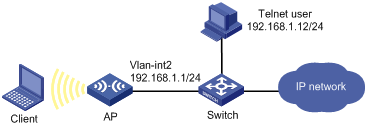
AAA configuration example
Network requirements
As shown in Figure 6, configure the AP to perform local authentication and authorization for Telnet users.
Configuration procedure
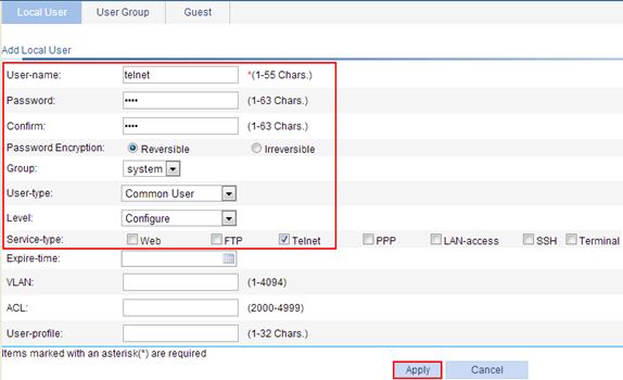
1. Configure a local user:
a. Select Authentication > Users from the navigation tree.
b. Click Add to enter the local user configuration page.
c. Enter the username telnet.
d. Enter the password abcd.
e. Enter abcd again to confirm the password.
f. Select Reversible for Password Encryption.
g. Select the user type Common User.
h. Select the level Configure.
i. Select the service type Telnet.
j. Click Apply.
Figure 7 Configuring a local user
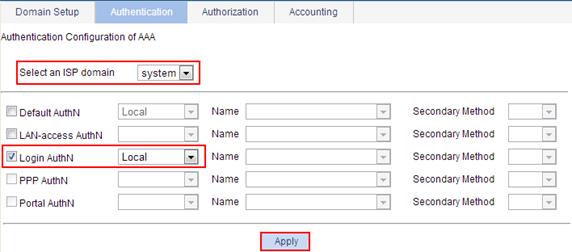
2. Configure the ISP domain system to use local authentication for login users:
a. Select Authentication > AAA from the navigation tree.
b. Click the Authentication tab.
c. Select the domain system.
d. Select Login AuthN, and select the authentication method Local.
e. Click Apply.
A configuration progress dialog box appears.
f. After the configuration process is complete, click Close.
Figure 8 Configuring the ISP domain to use local authentication for login users
3. Configure the ISP domain system to use local authorization for login users:
a. Select Authentication > AAA from the navigation tree.
b. Click the Authorization tab.
c. Select the domain system.
d. Select Login AuthZ, and select the authorization method Local.
e. Click Apply.
A configuration progress dialog box appears.
f. After the configuration process is complete, click Close.
Figure 9 Configuring the ISP domain to use local authorization for login users
4. In the CLI, enable the Telnet server, and configure the AP to use AAA for Telnet users.
<AP> system-view
[AP] telnet server enable
[AP] user-interface vty 0 4
[AP-ui-vty0-4] authentication-mode scheme
[AP-ui-vty0-4] quit
5. Verify the configuration.
Telnet to the AP and enter username telnet@system and password abcd. You will be serviced as a user in the domain system.
Remote Authentication Dial-In User Service (RADIUS) is a distributed information interaction protocol that uses a protocol for implementing client/server model to implement AAA. It can protect networks against unauthorized access and is often used in network environments that require high security and remote user access.
RADIUS uses UDP port 1812 for authentication and UDP port 1813 for accounting.
RADIUS was originally designed for dial-in user access. With the addition of new access methods, RADIUS has been extended to support additional access methods, for example, Ethernet and ADSL. RADIUS provides access authentication, authorization, and accounting services. The accounting function collects and records network resource usage information.
For more information about AAA and RADIUS, see Security Configuration Guide.
Configuring a RADIUS scheme
To configure a RADIUS scheme:
1. Select Authentication > RADIUS from the navigation tree.
Figure 10 RADIUS scheme list
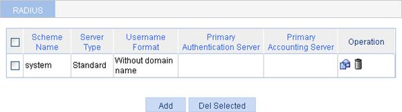
2. Click Add.
Figure 11 RADIUS scheme configuration page
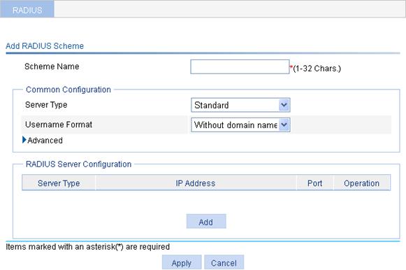
3. Enter a name for the scheme.
4. Configure the parameters, as described in Table 5.
|
Item |
Description |
|
Server Type |
Select the type of the RADIUS servers supported by the device, which can be: · Standard—Standard RADIUS servers. The RADIUS client and server communicate by using the standard RADIUS protocol and packet format defined in RFC 2865/2866 or later. · Extended—Extended RADIUS servers, usually running on IMC. The RADIUS client and server communicate by using a proprietary RADIUS protocol and packet format. |
|
Username Format |
Select the format for usernames sent to the RADIUS server. Typically, a username is in the format of userid@isp-name, of which isp-name is used by the device to determine the ISP domain for the user. If a RADIUS server does not accept a username that contains an ISP domain name, configure the device to remove the domain name of a username before sending the username to the RADIUS server. · Original format—Configure the device to send the username of a user on an "as is" basis. · With domain name—Configure the device to include the domain name in a username. · Without domain name—Configure the device to remove any domain name from a username. |
5. Click the expand button before Advanced in the Common Configuration area to expand the advanced configuration area.
Figure 12 Common configuration area
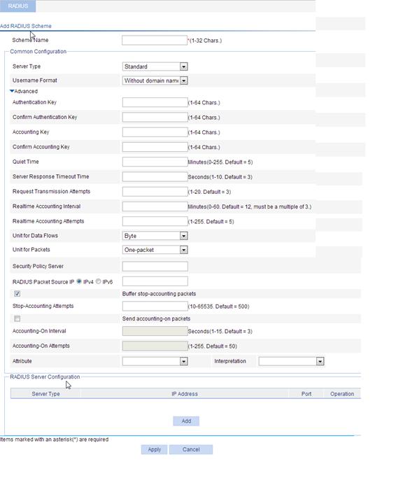
6. Configure the parameters, as described in Table 6.
|
Item |
Description |
|
Authentication Key Confirm Authentication Key Accounting Key Confirm Accounting Key |
Set the shared key for RADIUS authentication packets and that for RADIUS accounting packets. The RADIUS client and the RADIUS authentication/accounting server use MD5 to encrypt RADIUS packets. They verify the validity of packets through the specified shared key. The client and the server can receive and respond to packets from each other only when they use the same shared key.
· The shared keys configured on the device must be consistent with those configured on the RADIUS servers. · The shared keys configured in the common configuration part are used only when no corresponding shared keys are configured in the RADIUS server configuration part. |
|
Quiet Time |
Set the time the device keeps an unreachable RADIUS server in the blocked state. If you set the quiet time to 0, when the device needs to send an authentication or accounting request but finds that the current server is unreachable, it does not change the server's status that it maintains. It simply sends the request to the next server in the active state. As a result, when the device needs to send a request of the same type for another user, it still tries to send the request to the server because the server is in the active state. You can use this parameter to control whether the device changes the status of an unreachable server. For example, if you determine that the primary server is unreachable because the device's port for connecting the server is out of service temporarily or the server is busy, you can set the time to 0 so that the device uses the primary server as much. |
|
Server Response Timeout Time Request Transmission Attempts |
Set the RADIUS server response timeout time, and the maximum number of attempts for transmitting a RADIUS packet to a single RADIUS server. RADIUS uses UDP packets to carry data. If the device sends a RADIUS request to a RADIUS server but receives no response in the specified server response timeout time, it retransmits the request. If the number of transmission attempts exceeds the limit but the device still does not receive a response from the RADIUS server, the device tries to communicate with another server. If no active server exists, the device considers the request a failure.
The server response timeout time multiplied by the maximum number of RADIUS packet transmission attempts must not exceed 75. |
|
Realtime Accounting Interval |
Set the interval for sending real-time accounting information. The interval must be a multiple of 3. To implement real-time accounting, the device must send real-time accounting packets to the accounting server for online users periodically. Different real-time accounting intervals impose different performance requirements on the NAS and the RADIUS server. A shorter interval helps achieve higher accounting precision but requires higher performance. Use a longer interval when a large number of users (1000 or more) exist. For more information about the recommended real-time accounting intervals, see "Configuration guidelines." |
|
Realtime Accounting Attempts |
Set the maximum number of attempts for sending a real-time accounting request. |
|
Unit for Data Flows |
Specify the unit for data flows sent to the RADIUS server, which can be: · Byte. · Kilo-byte. · Mega-byte. · Giga-byte.
The units specified on the NAS must be consistent with those configured on the RADIUS server. Otherwise, accounting might be wrong. |
|
Unit for Packets |
Specify the unit for data packets sent to the RADIUS server, which can be: · One-packet. · Kilo-packet. · Mega-packet. · Giga-packet.
The units specified on the NAS must be consistent with those configured on the RADIUS server. Otherwise, accounting might be wrong. |
|
Security Policy Server |
Specify the IP address of the security policy server. |
|
RADIUS Packet Source IP |
Specify the source IP address for the device to use in RADIUS packets sent to the RADIUS server. The source IP address of RADIUS packets that a NAS sends must match the IP address of the NAS configured on the RADIUS server. A RADIUS server identifies a NAS by its IP address. Usually, the source address of outgoing RADIUS packets can be the IP address of the NAS's any interface that can communicate with the RADIUS server. In some special scenarios, however, you must change the source IP address. For example, if a NAT device is present between the NAS and the RADIUS server, the source IP address of outgoing RADIUS packets must be a public IP address of the NAS. If you do not specify this source IP address, the IP address of the outbound interface specified by the route is used.
This source IP address and the RADIUS server IP address specified in the RADIUS scheme must be of the same version. Otherwise, the configuration cannot take effect. |
|
Buffer stop-accounting packets |
Enable or disable buffering of stop-accounting requests for which no responses are received. |
|
Stop-Accounting Attempts |
Set the maximum number of stop-accounting attempts. The maximum number of stop-accounting attempts, together with some other parameters, controls how the NAS deals with stop-accounting request packets. Suppose that the RADIUS server response timeout period is three seconds, the maximum number of transmission attempts is five, and the maximum number of stop-accounting attempts is 20. For each stop-accounting request, if the device receives no response within three seconds, it retransmits the request. If it receives no responses after retransmitting the request five times, it considers the stop-accounting attempt a failure, buffers the request, and makes another stop-accounting attempt. If 20 consecutive attempts fail, the device discards the request. |
|
Send accounting-on packets |
Enable or disable the accounting-on feature. The accounting-on feature enables a device to send accounting-on packets to RADIUS servers after it reboots, making the servers forcedly log out users who logged in through the device before the reboot.
When enabling the accounting-on feature on a device for the first time, you must save the configuration so that the feature takes effect after the device reboots. |
|
Accounting-On Interval |
Set the interval for sending accounting-on packets. This field is configurable only after you select the Send accounting-on packets box. |
|
Accounting-On Attempts |
Set the maximum number of accounting-on packets transmission attempts. This field is configurable only after you select the Send accounting-on packets box. |
|
Attribute Interpretation |
Enable the device to interpret the RADIUS class attribute as CAR parameters. |
7. In the RADIUS Server Configuration area, click Add.
Figure 13 RADIUS server configuration page
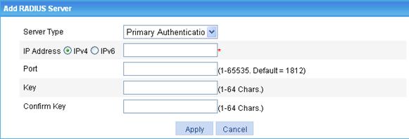
8. Configure the parameters, as described in Table 7.
9. Click Apply to add the server.
10. Repeat step 7 to step 9 to add more servers.
11. Click Apply on RADIUS scheme configuration page to complete the RADIUS scheme configuration.
|
Item |
Description |
|
Server Type |
Select the type of the RADIUS server to be configured. Possible values include primary authentication server, primary accounting server, secondary authentication server, and secondary accounting server. |
|
IP Address |
Specify the IPv4 or IPv6 address of the RADIUS server. The IP addresses of the primary and secondary servers for a scheme must be different. Otherwise, the configuration fails. RADIUS server addresses in the same scheme must use the same IP version. |
|
Port |
Specify the UDP port of the RADIUS server. |
|
Key Confirm Key |
Specify the shared key for communication with the RADIUS server. If no shared key is specified, the shared key specified in the common configuration part is used. |
RADIUS configuration example
Network requirements
Configure the AP to communicate with the RADIUS server, which runs on IMC, for Telnet user authentication, authorization, and accounting (online duration statistics):
· Set the shared key for secure communication between the RADIUS server and AP to expert.
· Set the authentication/authorization port and accounting port to 1812 and 1813, respectively.
· Configure the AP to carry the domain name of a username before sending it to the RADIUS server.
· Configure an account for the Telnet user, with the username hello@system and the password abc. The user has the privilege level of 3 after passing authentication.
Configuring the RADIUS server
This section assumes that the RADIUS server runs on IMC PLAT 7.0 (E0202) and IMC UAM 7.0 (E0202).
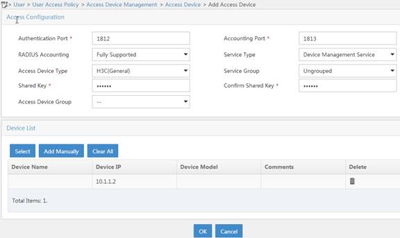
1. Add the AP to IMC as an access device:
a. Log in to IMC.
b. Click the User tab.
c. Select User Access Policy > Access Device Management > Access Device from the navigation tree.
d. Click Add.
e. Set the shared key for authentication and accounting to expert.
f. Select Device Management Service as the service type.
g. Select the access device from the device list or manually add the device with the IP address 10.1.1.2.
The IP address of the access device must be the same as the source IP address that the AP uses for outgoing RADIUS packets. By default, the AP uses the IP address of the outbound interface as the source IP address for outgoing RADIUS packets.
h. Use the default values for other parameters.
i. Click OK.
Figure 15 Adding an access device
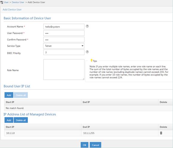
2. Add a user account for device management:
a. Click the User tab.
b. Select Device User from the navigation tree.
c. Click Add.
d. Enter hello@system as the username.
e. Enter abc as the password and confirm the password.
f. Select Telnet as the service type.
g. Set the EXEC privilege level to 3.
This value identifies the privilege level of the Telnet user after login, which is 0 by default.
h. Specify the IP address range of the hosts to be managed as 10.1.1.0 to 10.1.1.255. The IP address range must contain the IP address of the access device.
i. Click Add.
j. Click OK.
Figure 16 Adding a user account for device management
Configuring the AP
1. Configure RADIUS scheme system:
a. Select Authentication > RADIUS from the navigation tree.
b. Click Add.
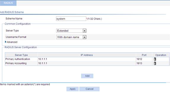
c. To add a RADIUS scheme, enter system as the scheme name, select Extended as the server type, and select With domain name for the username format.
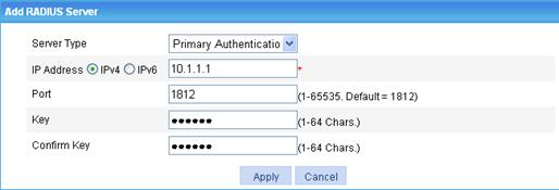
d. In the RADIUS Server Configuration area, to add the primary authentication server, click Add, select Primary Authentication as the server type, enter 10.1.1.1 as the IP address, enter 1812 as the port, enter expert as the key, type expert to confirm the key, and click Apply.
Figure 17 RADIUS authentication server configuration page
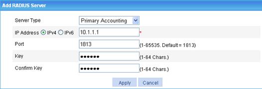
e. In the RADIUS Server Configuration area, to add a RADIUS accounting server, click Add again, select Primary Accounting as the server type, enter 10.1.1.1 as the IP address, enter 1813 as the port, enter expert as the key, enter expert to confirm the key, and click Apply.
The RADIUS scheme configuration page refreshes and the added servers appear in the server list.
Figure 18 RADIUS accounting server configuration page
f. Click Apply.
Figure 19 RADIUS scheme configuration
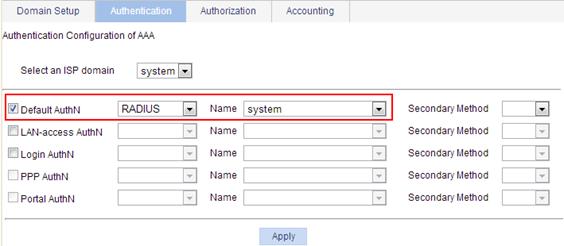
2. Configure the authentication method for the ISP domain system:
a. Click the Authentication tab.
b. Select the domain name system.
c. Select Default AuthN, and then select RADIUS as the authentication mode.
d. Select the scheme system.
e. Click Apply.
A configuration progress dialog box appears.
f. Click Close after the configuration process is complete.
Figure 20 Configuring the AAA authentication method for the ISP domain
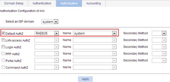
3. Configure the authorization method for the ISP domain system:
a. Click the Authorization tab.
b. Select the domain name system.
c. Select Default AuthZ, and then select RADIUS as the authorization mode.
d. Select the scheme system.
e. Click Apply.
A configuration progress dialog box appears.
f. Click Close after the configuration process is complete.
Figure 21 Configuring the AAA authorization method for the ISP domain
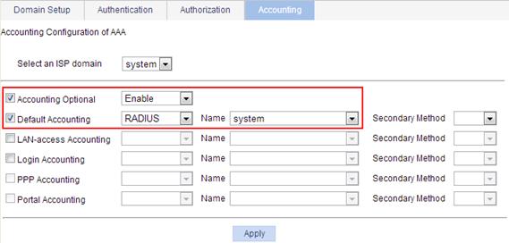
4. Configure the AAA accounting method for the ISP domain, and enable accounting optional:
a. Click the Accounting tab.
b. Select the domain name system.
c. Select Accounting Optional, and then select Enable from the list.
d. Select Default Accounting, and then select RADIUS as the accounting mode.
e. Select the scheme system.
f. Click Apply.
A configuration progress dialog box appears.
g. Click Close after the configuration process is complete.
Figure 22 Configuring the AAA accounting method for the ISP domain
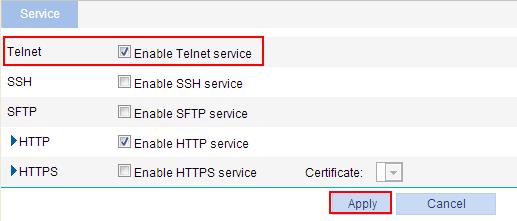
5. Enable the Telnet service:
a. Select Network > Service from the navigation tree.
b. Select Enable Telnet service.
c. Click Apply.
Figure 23 Enabling the Telnet service
6. In the CLI, configure the VTY user interfaces to use AAA for user access control.
<AP> system-view
[AP] user-interface vty 0 4
[AP-ui-vty0-4] authentication-mode scheme
[AP-ui-vty0-4] quit
Verifying the configuration
From the Telnet client, enter the username hello@bbb and password abc. The user interface of the AP appears and all the commands of level 0 to level 3 are available.
Configuration guidelines
When you configure the RADIUS client, follow these guidelines:
· Accounting for FTP users is not supported.
· If you remove the accounting server used for online users, the device cannot send real-time accounting requests and stop-accounting messages for the users to the server, and the stop-accounting messages are not buffered locally.
· The status of RADIUS servers, blocked or active, determines which servers the device will communicate with or turn to when the current servers are not available. In practice, you can specify one primary RADIUS server and multiple secondary RADIUS servers, with the secondary servers that function as the backup of the primary servers. Typically, the device chooses servers based on these rules:
¡ When the primary server is in the active state, the device communicates with the primary server. If the primary server fails, the device changes the state of the primary server to blocked, starts a quiet timer for the server, and turns to a secondary server in the active state (a secondary server configured earlier has a higher priority). If the secondary server is unreachable, the device changes the state of the secondary server to blocked, starts a quiet timer for the server, and continues to check the next secondary server in the active state. This search process continues until the device finds an available secondary server or has checked all secondary servers in the active state. If the quiet timer of a server expires or an authentication or accounting response is received from the server, the status of the server changes back to active automatically, but the device does not check the server again during the authentication or accounting process. If no server is found reachable during one search process, the device considers the authentication or accounting attempt a failure.
¡ Once the accounting process of a user starts, the device keeps sending the user's real-time accounting requests and stop-accounting requests to the same accounting server. If you remove the accounting server, real-time accounting requests and stop-accounting requests for the user can no longer be delivered to the server.
¡ If you remove an authentication or accounting server in use, the communication of the device with the server will soon time out, and the device will look for a server in the active state by checking any primary server first and then the secondary servers in the order they are configured.
¡ When the primary server and secondary servers are all in the blocked state, the device communicates with the primary server. If the primary server is available, its statues changes to active. Otherwise, its status remains to be blocked.
¡ If one server is in the active state but all the others are in the blocked state, the device only tries to communicate with the server in the active state, even if the server is unavailable.
¡ After receiving an authentication/accounting response from a server, the device changes the status of the server identified by the source IP address of the response to active if the current status of the server is blocked.
· Set a proper real-time accounting interval based on the number of users.
Table 8 Recommended real-time accounting intervals
|
Number of users |
Real-time accounting interval (in minutes) |
|
1 to 99 |
3 |
|
100 to 499 |
6 |
|
500 to 999 |
12 |
|
≥1000 |
≥15 |
HW Terminal Access Controller Access Control System (HWTACACS) is an enhanced security protocol based on TACACS (RFC 1492). Similar to RADIUS, it uses a client/server (C/S) model for information exchange between network access server (NAS) and HWTACACS server.
HWTACACS is mainly used to provide AAA services for PPP, VPDN, and terminal users. In a typical HWTACACS scenario, some terminal users need to log in to the NAS for operations. Working as the HWTACACS client, the NAS sends users' usernames and passwords to the HWTACACS sever for authentication. After passing authentication and getting authorized rights, a user logs in to the device and performs operations. The HWTACACS server records the operations that each user performs. For more information about HWTACACS, see Security Configuration Guide.
Recommended configuration procedure
|
Task |
Description |
|
Required. Create an HWTACACS scheme named system. By default, no HWTACACS scheme exists.
In the Web interface, only one HWTACACS scheme can be configured, and the scheme is named system. |
|
|
Authentication server and authorization server are mandatory and accounting server is optional. Specify the primary and the secondary HWTACACS servers. By default, no server is specified.
If redundancy is not required, specify only the primary HWTACACS authentication server. |
|
|
Optional. This section describes how to configure the parameters that are necessary for information exchange between the device and HWTACACS server. |
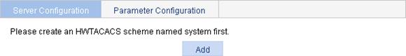
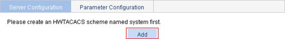
Creating the HWTACACS scheme system
1. Select Authentication > HWTACACS from the navigation tree.
2. Click Add.
If the HWTACACS scheme system already exists, you enter the HWTACACS server configuration page after selecting Authentication > HWTACACS from the navigation tree.
Figure 24 Creating the HWTACACS scheme system
Configuring HWTACACS servers for the scheme
1. Select Authentication > HWTACACS from the navigation tree.
Figure 25 HWTACACS server configuration
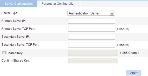
2. Specify HWTACACS servers and configure relevant parameters, as described in Table 9.
3. Click Apply.
|
Item |
Description |
|
Server Type |
Select the type of the server to be configured, which can be Authentication Server, Authorization Server and Accounting Sever. |
|
Primary Server IP |
Enter the IP address of the primary server. When no primary server is specified, the primary server IP address and the primary server TCP port are empty. If you leave the IP address field empty, the primary server (if configured) will be removed. The specified IP address of the primary server cannot be the same as that of the secondary server. |
|
Primary Server TCP Port |
Enter the TCP port of the primary server. You must configure different TCP port numbers for different service types. |
|
Secondary Server IP |
Enter the IP address of the secondary server. When no secondary server is specified, the secondary server IP and the secondary server TCP port are empty. If you leave the IP address field empty, the secondary server (if configured) will be removed. The specified IP address of the primary server cannot be the same as that of the secondary server. |
|
Secondary Server TCP Port |
Enter the TCP port of the secondary server. You must configure different TCP port numbers for different service types. |
|
Shared Key Confirm Shared Key |
Select the Shared Key box, enter the shared key of the server in the text box, and enter it again in the Confirm Shared Key field. The HWTACACS client (the NAS) and HWTACACS server use the MD5 algorithm to encrypt packets exchanged between them and a shared key to verify the packets. They can properly exchange packets only when they use the same shared key. |
Configuring HWTACACS parameters for the scheme
1. Select Authentication > HWTACACS from the navigation tree.
2. Click the Parameter Configuration tab.
Figure 26 HWTACACS parameter configuration
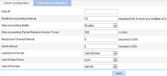
3. Configure HWTACACS parameters, as described in Table 10.
4. Click Apply.
|
Item |
Description |
|
NAS-IP |
Source IP address for the device to use in HWTACACS packets to be sent to the HWTACACS server. Use a loopback interface address instead of a physical interface address as the source IP address to make sure the response packets from the server can reach the device when the physical interface is down. |
|
Realtime-Accounting Interval |
Real-time accounting interval, whose value must be a multiple of 3. To implement real-time accounting on users, it is necessary to set the real-time accounting interval. After this parameter is specified, the device will send the accounting information of online users to the HWTACACS server every the specified interval. According to the protocol, the device will not disconnect the online users even if the server does not make any response properly. If you leave this field blank, the real-time accounting interval is restored to the default value.
Consider the performance of the NAS and the HWTACACS server when you set the real-time accounting interval. A short interval requires higher performance. Use a longer interval when the number of users exceeds 1000. For the recommended ratios of the interval to the number of users, see "Configuration guidelines." |
|
Stop-Accounting Buffer |
Enable or disable buffering stop-accounting requests without responses in the device. Because stop-accounting requests affect the charge to users, a NAS must make its best effort to send every stop-accounting request to the HWTACACS accounting servers. For each stop-accounting request getting no response in the specified period of time, the NAS buffers and resends the packet until it receives a response or the number of transmission retries reaches the configured limit. In the latter case, the NAS discards the packet. |
|
Stop-Accounting Packet Retransmission Times |
The maximum number of stop-accounting packet transmission attempts if no response is received for the stop-accounting packet. If stop-accounting buffer is disabled, this value is ineffective. If you leave this field blank, the number of retransmission times is restored to the default value. |
|
Response Timeout Interval |
Set the HWTACACS server response timeout time. If no response is received from the server within the timeout interval, it may lead to disconnection from the HWTACACS server. If you leave this field blank, the response timeout period is restored to the default value.
HWTACACS is based on TCP. The timeout of the server response timeout timer or the TCP timeout timer will cause the NAS to be disconnected from the HWTACACS server. |
|
Quiet Interval |
Specify the interval the primary server has to wait before being active. If you leave this field blank, the quiet interval is restored to the default value. |
|
Username Format |
Set the format of the username sent to the HWTACACS server. A username is generally in the format of userid@isp-name, of which isp-name is used by the device to determine the ISP domain to which the user belongs. If an HWTACACS server does not accept a username including an ISP domain name, you can configure the device to remove the domain name before sending it to the HWTACACS server. Options include: · Without-domain—The device removes the domain name of a username that is to be sent to the RADIUS server. · With-domain—The device keeps the domain name of a username that is to be sent to the RADIUS server. |
|
Unit of Data Flows |
Specify the unit for data flows sent to the HWTACACS server for traffic accounting. Options include: · Byte. · Kilo-byte. · Mega-byte. · Giga-byte. If you leave the field blank, the default unit is used. |
|
Unit of Packets |
Specify the unit for data packets sent to the HWTACACS server for traffic accounting. Options include: · Packet. · Kilo-packet. · Mega-packet. · Giga-packet. If you leave the field blank, the default unit is used. |
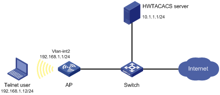
HWTACACS configuration example
Network requirements
As shown in Figure 27, configure the AP to use the HWTACACS server to provide authentication, authorization, and accounting services for the Telnet user. Set the shared keys for secure communication with the HWTACACS server to expert. Configure the AP to remove the domain name from a username sent to the HWTACACS server.
Configuring the HWTACACS server
On the HWTACACS server, set the shared keys to expert, add a Telnet user, and set a password for the user. (Details not shown.)
Configuring the AP
1. Create the HWTACACS scheme system:
a. From the navigation tree, select Authentication > HWTACACS.
b. On the page that appears, click Add.
Figure 28 Creating the HWTACACS scheme system
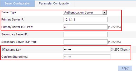
2. Configure the HWTACACS authentication server:
a. On the HWTACACS server configuration page (see Figure 29), select the server type Authentication Server.
b. Enter 10.1.1.1 as the IP address of the primary server.
c. Enter 49 as the TCP port number of the primary server.
d. Select Shared Key and enter expert as the shared key.
e. Click Apply.
Figure 29 Configuring the HWTACACS authentication server
3. Configure the HWTACACS authorization server:
a. On the HWTACACS server configuration page (see Figure 29), select the server type Authorization Server.
b. Enter 10.1.1.1 as the IP address of the primary server.
c. Enter 49 as the TCP port of the primary server.
d. Select Shared Key and enter expert as the shared key.
e. Click Apply.
4. Configure the HWTACACS accounting server:
a. On the HWTACACS server configuration page (see Figure 29), select the server type Accounting Server.
b. Enter 10.1.1.1 as the IP address of the primary server.
c. Enter 49 as the TCP port of the primary server.
d. Select Shared Key and enter expert as the shared key.
e. Click Apply.
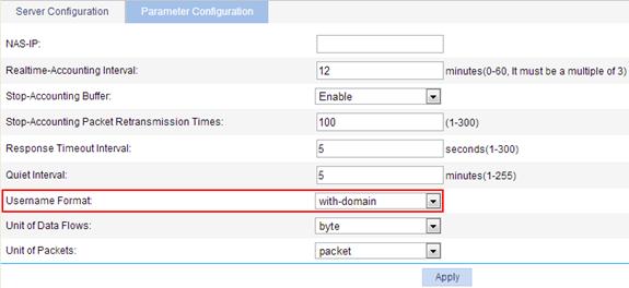
5. Configure the parameters for communication between the AP and the HWTACACS server:
a. From the navigation tree, select Authentication > HWTACACS.
b. Click the Parameter Configuration tab.
c. Select the username format without-domain.
d. Click Apply.
Figure 30 Configuring the parameters for communication
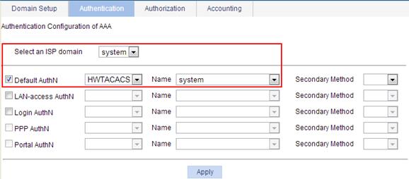
6. Configure an authentication method for the ISP domain system:
a. Click the Authentication tab.
b. Enter the domain name system.
c. Select Default AuthN, and then select HWTACACS from the following list.
d. Select the scheme system.
e. Click Apply.
A progress dialog box appears.
f. When the configuration progress is complete, click Close.
Figure 31 Configuring an authentication method for the ISP domain
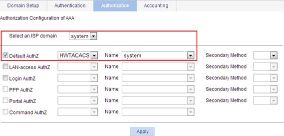
7. Configure an authorization method for the ISP domain system:
a. Click the Authorization tab.
b. Enter the domain name system.
c. Select Default AuthZ, and then select HWTACACS from the following list.
d. Select the scheme name system.
e. Click Apply.
A progress dialog box appears.
f. When the configuration progress is complete, click Close.
Figure 32 Configuring an authorization method for the ISP domain
8. Configure an accounting method for the ISP domain system:
a. Click the Accounting tab.
b. Enter the domain name system.
c. Select Accounting Optional, and then select Enable from the following list.
d. Select Default Accounting, and then select HWTACACS from the following list.
e. Select the scheme name system.
f. Click Apply.
A progress dialog box appears.
g. When the configuration progress is complete, click Close.
Figure 33 Configuring an accounting method for the ISP domain
9. In the CLI, enable the Telnet service on the AP, and configure the AP to use AAA for Telnet users.
<AP> system-view
[AP] telnet server enable
[AP] user-interface vty 0 4
[AP-ui-vty0-4] authentication-mode scheme
[AP-ui-vty0-4] quit
Verifying the configuration
On the Telnet client, enter the username in the format userid@test and the password. Then you can access the user interface of the AP.
Configuration guidelines
When you configure the HWTACACS client, follow these guidelines:
· You cannot delete an HWTACACS scheme that is being used for users, nor can you change the server IP addresses of the scheme.
· Except for deleting HWTACACS schemes and changing the IP addresses of the HWTACACS servers, you can make any changes to HWTACACS parameters, no matter whether there are users online or not.
· HWTACACS authentication must work with HWTACACS authorization. If only HWTACACS authentication is configured, but HWTACACS authorization is not, users cannot log in.
· You can remove an authentication/authorization/accounting server only when no active TCP connection for sending authentication/authorization/accounting packets is using it.
· HWTACACS does not support accounting for FTP users.
· Determine the real-time accounting interval based on the number of users, as shown in Table 11.
Table 11 Recommended real-time accounting interval settings
|
Number of users |
Real-time accounting interval (in minutes) |
|
1 to 99 |
3 |
|
100 to 499 |
6 |
|
500 to 999 |
12 |
|
≥1000 |
≥15 |
Overview
This module allows you to configure local users, user groups, guests, and user profiles.
Local user
A local user is an account configured on the device. It is uniquely identified by the username and has a set of user attributes, such as the password, user type, service type, and authorization attribute. For a user to pass local authentication, you must add a local user for the user on the device. For more information about local authentication, see "Configuring AAA."
User group
A user group consists of a group of local users and has a set of user attributes. You can configure user attributes for a user group to implement centralized management of user attributes for the local users in the group. All local users in a user group inherit the user attributes of the group, but if you configure user attributes for a local user, the settings of the local user take precedence over the settings for the user group.
By default, every newly added local user belongs to a user group named system, which is automatically created by the system.
Guest
A guest is a local user for specific applications. If portal or LAN-access users need to access the network temporarily, you can establish a guest account for them and control access of the users as required.
Configuring a local user
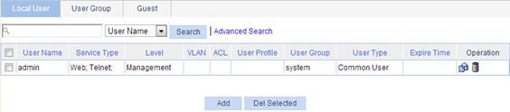
1. Select Authentication > Users from the navigation tree.
The local user management page appears, displaying information about all local users including common users, security log administrators, guest administrators, and guests.
On the Local User tab, you can modify a guest user, but the user type changes to another one after your modification.
Figure 34 Local user management page
2. Click Add to enter the local user configuration page, where you can create a local user of any type except guest.
Figure 35 Local user configuration page

3. Configure the local user, as described in Table 12.
4. Click Apply.
|
Item |
Description |
|
User-name |
Specify a name for the local user. |
|
Password Confirm |
Specify a password for the local user and confirm the password. The two passwords must be identical.
Leading spaces of a password are ignored. |
|
Password Encryption |
Set the encryption method for storing users' passwords: · Reversible—The device stores passwords by using reversible encryption. · Irreversible—The device stores passwords by using irreversible encryption. |
|
Group |
Select a user group for the local user. For information about user group configuration, see "Configuring a user group." |
|
User-type |
Specify the user type for the local user. Available values for this field include: · Common User. · Security Log Admin—Users of this type can only manage security log files in the Web interface. Only Users of this type can manage security log files. The device does not support the configuration of this user type. · Guest Admin—Users of this type can only manage guest accounts in the Web interface, log in to the Authentication > User > [Guest] page to add, modify, or delete a guest user. |
|
Level |
Select an authorization level for the local user, which can be Visitor, Monitor, Configure, or Management, in ascending order of priority. A local user has the rights of the specified level and all levels lower than the specified level (if any). · Visitor—A user of this level can perform ping and trace route operations but cannot read any data from the device or configure the device. · Monitor—A user of this level can read data from the device but cannot configure the device. · Configure—A user of this level can read data from the device and configure the device but cannot upgrade the device software, add/delete/modify users, or backup/restore configuration files. · Management—A user of this level can perform all operations.
This option is effective only for common users who use Web, FTP, Telnet, or SSH services. |
|
Service-type |
Select the service types for the local user to use, including Web, FTP, Telnet, PPP, portal, LAN access (accessing through the Ethernet, such as 802.1X users), and SSH.
· If you do not specify any service type for a local user who uses local authentication, the user cannot pass authentication and cannot log in. · The service type of the guest administrator and security log administrator is Web. · The service type of the guests is portal and LAN access. |
|
Expire-time |
Specify an expiration time for the local user. When authenticating a local user with the expiration time parameter configured, the access device checks whether the expiration time has elapsed. If not, the device permits the user to log in. |
|
VLAN |
Specify the VLAN to be authorized to the local user after the user passes authentication.
This option is effective only for common users who use portal or LAN access services. |
|
ACL |
Specify the ACL to be used by the access device to restrict the access of the local user after the user passes authentication.
This option is effective only for common users who use PPP, portal, or LAN access services. |
|
User-profile |
Specify the user profile for the local user. The device does not support the user profile configuration.
This option is effective only for common users who use PPP, portal, or LAN access services. |
Configuring a user group
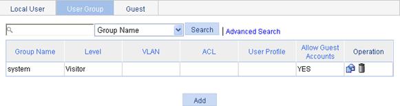
1. Select Authentication > Users from the navigation tree.
2. Click the User Group tab to enter the user group management page.
Figure 36 User group management page
3. Click Add to enter the user group configuration page.
Figure 37 User group configuration page
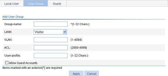
4. Configure the user group, as described in Table 13.
5. Click Apply.
|
Item |
Description |
|
Group-name |
Specify a name for the user group. |
|
Level |
Select an authorization level for the user group, which can be Visitor, Monitor, Configure, or Management, in ascending order of priority. |
|
VLAN |
Specify the VLAN to be authorized to a user in the user group after the user passes authentication. |
|
ACL |
Specify the ACL to be used by the access device to restrict the access of a user in the user group after the user passes authentication. |
|
User-profile |
Specify the user profile for the user group. The device does not support the user profile configuration. |
|
Allow Guest Accounts |
Specify whether to allow a guest to join the user group.
User group system is an optional group of guest accounts by default, and cannot be modified. |
Configuring a guest
Guests can be configured by common management-level users or guest administrators. For information about user type and authorization level, see Table 12.
Configuring a guest by a common management-level user
1. Select Authentication > Users from the navigation tree.
2. Click the Guest tab to enter the guest management page.
Figure 38 Guest management page
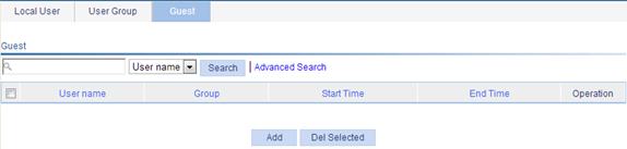
3. Click Add to add a guest.
Figure 39 Adding a guest
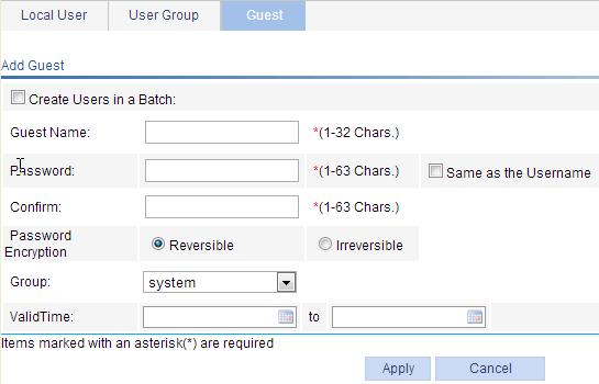
4. Configure a single guest or a batch of guests, as described in Table 14.
5. Click Apply.
|
Item |
Description |
|
Create Users in a Batch |
Specify whether to create a batch of guest accounts. |
|
Guest Name |
To create a single guest account, specify a username for the account. |
|
Username Prefix Number of Users |
To create a batch of guest accounts, specify the username prefix and the number of guest accounts. For example, if you enter the username prefix abc and the number 50, 50 guest accounts will be created, with the usernames from abc0 to abc49. |
|
Password Same as the Username Confirm |
Specify a password for the account or accounts and confirm the password, or select Same as the Username to use the usernames as the passwords.
Leading spaces of a password are ignored. |
|
Password Encryption |
Set the encryption method for storing users' passwords: · Reversible—The device stores passwords by using reversible encryption. · Irreversible—The device stores passwords by using irreversible encryption. |
|
Group |
Select a group to add the guest to the group. |
|
ValidTime |
Specify a validity time for the guest. When authenticating a guest with the validity time parameter configured, the access device checks whether the validity time has elapsed. If yes, the device denies the login request. |
Configuring a guest by a guest administrator
Guest administrators can manage only guest accounts and can only manage guest accounts in the Web interface.
To configure a guest:
1. Log in to the device as a guest administrator and select Authentication > User from the navigation tree.
The guest management page appears.
Figure 40 Guest management page
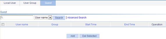
2. Click Add to enter the guest configuration page.
3. Configure a single guest or a batch of guests, as described in Table 14.
4. Click Apply.
Overview
Public Key Infrastructure (PKI) offers an infrastructure for securing network services. PKI, also called asymmetric key infrastructure, uses a pair of keys (one private and one public) for data encryption and decryption. Data encrypted with the public key can be decrypted only with the private key, and vice versa.
PKI uses digital certificates to distribute and employ public keys, and provides network communication and e-commerce with security services such as user authentication, data confidentiality, and data integrity.
H3C's PKI system provides certificate management for SSL.
The PKI technology can satisfy the security requirements of online transactions. As an infrastructure, PKI has a wide range of applications. Here are some application examples:
· VPN—A VPN is a private data communication network built on the public communication infrastructure. A VPN can leverage network layer security protocols (for instance, IPsec) in conjunction with PKI-based encryption and digital signature technologies to achieve confidentiality.
· Secure email—Emails require confidentiality, integrity, authentication, and non-repudiation. PKI can address these needs. A common secure email protocol is S/MIME, which is based on PKI and allows for transfer of encrypted mails with signature.
· Web security—For Web security, two peers can establish an SSL connection first for transparent and secure communications at the application layer. With PKI, SSL enables encrypted communications between a browser and a server. Both the communication parties can verify the identity of each other through digital certificates. For more information about PKI, see Security Configuration Guide.
Recommended configuration procedures
The system supports the following PKI certificate request modes:
· Manual—In manual mode, you need to manually retrieve a CA certificate, generate a local RSA key pair, and submit a local certificate request for an entity.
· Auto—In auto mode, an entity automatically requests a certificate through SCEP when it has no local certificate or the present certificate is about to expire.
You can specify the PKI certificate request mode for a PKI domain. Different PKI certificate request modes require different configurations.
Recommended configuration procedure for manual request
|
Step |
Remarks |
|
Required. Create a PKI entity and configure the identity information. A certificate is the binding of a public key and the identity information of an entity, where the distinguished name (DN) shows the identity information of the entity. A CA identifies a certificate applicant uniquely by an entity DN. The DN settings of an entity must be compliant to the CA certificate issue policy. Otherwise, the certificate request might be rejected. You must know the policy to determine which entity parameters are mandatory or optional. |
|
|
Required. Create a PKI domain, setting the certificate request mode to Manual. Before requesting a PKI certificate, an entity needs to be configured with some enrollment information, which is called a PKI domain. A PKI domain is intended only for convenience of reference by other applications like IKE and SSL, and has only local significance. |
|
|
Required. Generate a local RSA key pair. By default, no local RSA key pair exists. Generating an RSA key pair is an important step in certificate request. The key pair includes a public key and a private key. The private key is kept by the user, and the public key is transferred to the CA along with some other information.
If a local certificate already exists, you must remove the certificate before generating a new key pair, so as to keep the consistency between the key pair and the local certificate. |
|
|
Required. Certificate retrieval serves the following purposes: · Locally store the certificates associated with the local security domain for improved query efficiency and reduced query count, · Prepare for certificate verification.
If a local CA certificate already exists, you cannot perform the CA certificate retrieval operation. This mechanism helps avoid possible mismatch between certificates and registration information resulting from relevant changes. To retrieve the CA certificate, you must remove the CA certificate and local certificate first. |
|
|
Required. When requesting a certificate, an entity introduces itself to the CA by providing its identity information and public key, which are the major components of the certificate. A certificate request can be submitted to a CA in online mode or offline mode. · In online mode, if the request is granted, the local certificate is retrieved to the local system automatically. · In offline mode, you must retrieve the local certificate by an out-of-band means.
If a local certificate already exists, you cannot perform the local certificate retrieval operation. This mechanism helps avoid possible mismatch between the local certificate and registration information resulting from relevant changes. To retrieve a new local certificate, you must remove the CA certificate and local certificate first. |
|
|
Optional. If the certificate to be retrieved contains an RSA key pair, you must destroy the existing RSA key pair. Otherwise, the certificate cannot be retrieved. Destroying the existing RSA key pair also destroys the corresponding local certificate. |
|
|
Required if you request a certificate in offline mode. Retrieve an existing certificate and display its contents.
· If you request a certificate in offline mode, you must retrieve the CA certificate and local certificate by an out-of-band means. · Before retrieving a local certificate in online mode, be sure to complete LDAP server configuration. |
|
|
Optional. Retrieve a CRL and display its contents. |
Recommended configuration procedure for automatic request
|
Step |
Remarks |
|
Required. Create a PKI entity and configure the identity information. A certificate is the binding of a public key and the identity information of an entity, where the DN shows the identity information of the entity. A CA identifies a certificate applicant uniquely by an entity DN. The DN settings of an entity must be compliant to the CA certificate issue policy. Otherwise, the certificate request might be rejected. You must know the policy to determine which entity parameters are mandatory or optional. |
|
|
Required. Create a PKI domain, setting the certificate request mode to Auto. Before requesting a PKI certificate, an entity needs to be configured with some enrollment information, which is called a PKI domain. A PKI domain is intended only for convenience of reference by other applications like IKE and SSL, and has only local significance. |
|
|
Optional. If the certificate to be retrieved contains an RSA key pair, you must destroy the existing RSA key pair. Otherwise, the certificate cannot be retrieved. Destroying the existing RSA key pair also destroys the corresponding local certificate. |
|
|
Optional. Retrieve an existing certificate and display its contents.
· Before retrieving a local certificate in online mode, be sure to complete LDAP server configuration. · If a CA certificate already exists, you cannot retrieve another CA certificate. This restriction avoids inconsistency between the certificate and registration information due to related configuration changes. To retrieve a new CA certificate, remove the existing CA certificate and local certificate first. |
|
|
Optional. Retrieve a CRL and display its contents. |
Creating a PKI entity
1. From the navigation tree, select Authentication > Certificate Management.
The PKI entity list page is displayed by default.
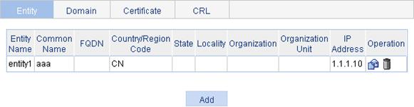
2. Click Add.
Figure 43 PKI entity configuration page
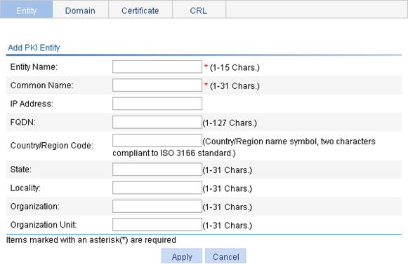
3. Configure the parameters, as described in Table 15.
4. Click Apply.
|
Item |
Description |
|
Entity Name |
Enter the name for the PKI entity. |
|
Common Name |
Enter the common name for the entity. |
|
IP Address |
Enter the IP address of the entity. |
|
FQDN |
Enter the FQDN for the entity. An FQDN is a unique identifier of an entity on the network. It consists of a host name and a domain name and can be resolved to an IP address. For example, www.whatever.com is an FQDN, where www indicates the host name and whatever.com the domain name. |
|
Country/Region Code |
Enter the country or region code for the entity. |
|
State |
Enter the state or province for the entity. |
|
Locality |
Enter the locality for the entity. |
|
Organization |
Enter the organization name for the entity. |
|
Organization Unit |
Enter the unit name for the entity. |
Creating a PKI domain
1. From the navigation tree, select Authentication > Certificate Management.
2. Click the Domain tab.
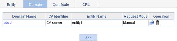
3. Click Add.
Figure 45 PKI domain configuration page
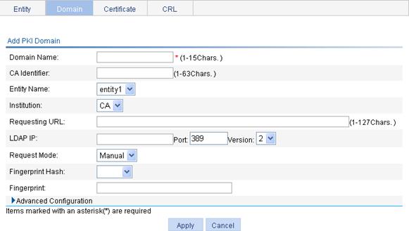
4. Configure the parameters, as described in Table 16.
5. Click Apply.
|
Item |
Description |
|
Domain Name |
Enter the name for the PKI domain. |
|
CA Identifier |
Enter the identifier of the trusted CA. An entity requests a certificate from a trusted CA. The trusted CA takes the responsibility of certificate registration, distribution, and revocation, and query. In offline mode, this item is optional. In other modes, this item is required. |
|
Entity Name |
Select the local PKI entity. When submitting a certificate request to a CA, an entity needs to show its identity information. Available PKI entities are those that have been configured. |
|
Institution |
Select the authority for certificate request. · CA—Entity requests a certificate from a CA. · RA—Entity requests a certificate from an RA. RA is recommended. |
|
Requesting URL |
Enter the URL of the RA. The entity will submit the certificate request to the server at this URL through the SCEP protocol. The SCEP protocol is intended for communication between an entity and an authentication authority. In offline mode, this item is optional. In other modes, this item is required.
This item does not support domain name resolution. |
|
LDAP IP |
Enter the IP address, port number and version of the LDAP server. In a PKI system, the storage of certificates and CRLs is a crucial problem, which is usually addressed by deploying an LDAP server.. |
|
Port |
|
|
Version |
|
|
Request Mode |
Select the online certificate request mode, which can be auto or manual. |
|
Password |
Set a password for certificate revocation and re-enter it for confirmation. The two boxes are available only when the certificate request mode is set to Auto.. |
|
Confirm Password |
|
|
Fingerprint Hash |
Specify the fingerprint used for verifying the CA root certificate. After receiving the root certificate of the CA, an entity needs to verify the fingerprint of the root certificate, namely, the hash value of the root certificate content. This hash value is unique to every certificate. If the fingerprint of the root certificate does not match the one configured for the PKI domain, the entity rejects the root certificate. · If you specify MD5 as the hash algorithm, enter an MD5 fingerprint. The fingerprint must a string of 32 characters in hexadecimal notation. · If you specify SHA1 as the hash algorithm, enter an SHA1 fingerprint. The fingerprint must a string of 40 characters in hexadecimal notation. · If you do not specify the fingerprint hash, do not enter any fingerprint. The entity does not verify the CA root certificate, and you must make sure the CA server is trusted.
The fingerprint must be configured if you specify the certificate request mode as Auto. If you specify the certificate request mode as Manual, you can leave the fingerprint settings null. If you do not configure the fingerprint, the entity does not verify the CA root certificate and you must make sure the CA server is trusted. |
|
Fingerprint |
|
|
Polling Count |
Set the polling interval and attempt limit for querying the certificate request status. After an entity makes a certificate request, the CA might need a long period of time if it verifies the certificate request in manual mode. During this period, the applicant needs to query the status of the request periodically to get the certificate as soon as possible after the certificate is signed.. |
|
Polling Interval |
|
|
Enable CRL Checking |
Select this box to specify that CRL checking is required during certificate verification. |
|
CRL Update Period |
Enter the CRL update period, that is, the interval at which the PKI entity downloads the latest CRLs. This item is available after you click the Enable CRL Checking box. By default, the CRL update period depends on the next update field in the CRL file. |
|
CRL URL |
Enter the URL of the CRL distribution point. The URL can be an IP address or a domain name. This item is available after you click the Enable CRL Checking box. If the URL of the CRL distribution point is not specified, get the CA certificate and a local certificate, and then get a CRL through SCEP. |
Generating an RSA key pair
1. From the navigation tree, select Authentication > Certificate Management.
2. Click the Certificate tab.
Figure 46 Certificate configuration page
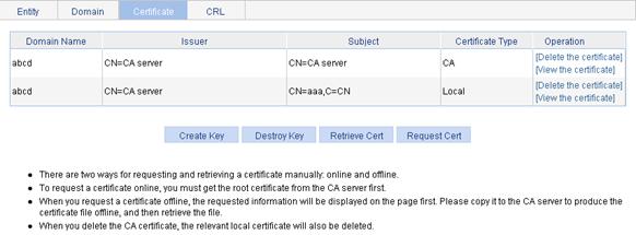
3. Click Create Key.
Figure 47 Key pair parameter configuration page
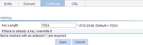
4. Set the key length.
5. Click Apply.
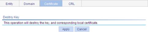
Destroying the RSA key pair
1. From the navigation tree, select Authentication > Certificate Management.
2. Click the Certificate tab.
3. Click Destroy Key.
4. Click Apply to destroy the existing RSA key pair and the corresponding local certificate.
Figure 48 Key pair destruction page
Retrieving and displaying a certificate
You can retrieve an existing CA certificate or local certificate from the CA server and save it locally. To do so, you can use offline mode or online mode. In offline mode, you must retrieve a certificate by an out-of-band means like FTP, disk, email and then import it into the local PKI system. By default, the retrieved certificate is saved in a file under the root directory of the device, and the filename is domain-name_ca.cer for the CA certificate, or domain-name_local.cer for the local certificate.
To retrieve a certificate:
1. From the navigation tree, select Authentication > Certificate Management.
2. Click the Certificate tab.
3. Click Retrieve Cert.
Figure 49 PKI certificate retrieval page
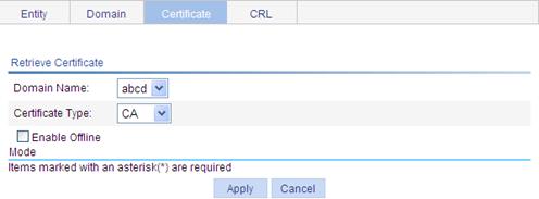
4. Configure the parameters, as described in Table 17.
5. Click Apply.
|
Item |
Description |
|
Domain Name |
Select the PKI domain for the certificate. |
|
Certificate Type |
Select the type of the certificate to be retrieved, which can be CA or local. |
|
Enable Offline Mode |
Click this box to retrieve a certificate in offline mode (that is, by an out-of-band means like FTP, disk, or email), and then import the certificate into the local PKI system. |
|
Get File From Device |
Specify the path and name of the certificate file to import if you enable offline mode: · If the certificate file is saved on the device, select Get File From Device and then specify the path and name of the file on the device. If no file is specified, the system, by default, gets the file domain-name_ca.cer (for the CA certificate) or domain-name_local.cer (for the local certificate) under the root directory of the device. · If the certificate file is saved on a local PC, select Get File From PC and. then specify the path and name of the file and specify the partition that saves the file.. |
|
Get File From PC |
|
|
Password |
If you retrieve the certificate in offline mode, enter the password for protecting the private key, which was specified when the certificate was exported. |
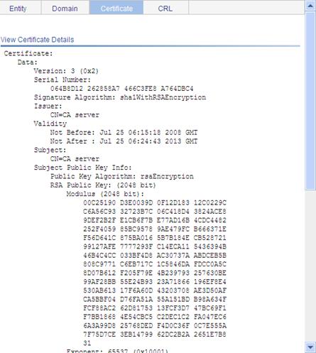
After retrieving a certificate, you can click View Cert corresponding to the certificate from the PKI certificates list to display the contents of the certificate.
Figure 50 Certificate information
Requesting a local certificate
1. From the navigation tree, select Authentication > Certificate Management.
2. Click the Certificate tab.
3. Click Request Cert.
Figure 51 Local certificate request page
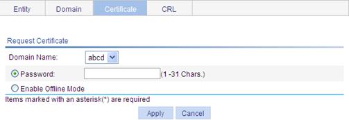
4. Configure the parameters, as described in Table 18.
|
Item |
Description |
|
Domain Name |
Select the PKI domain for the certificate. |
|
Password |
Enter the password for certificate revocation. |
|
Enable Offline Mode |
Select this option to request a certificate in offline mode, that is, by an out-of-band means like FTP, disk, or email. |
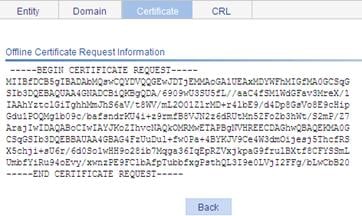
5. Click Apply.
If you request the certificate in online mode, the system displays "Certificate request has been submitted." Click OK to confirm. If you request the certificate in offline mode, the system displays the offline certificate request information. You can submit the information to the CA by an out-of-band means.
Figure 52 Offline certificate request information page
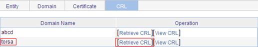
Retrieving and displaying a CRL
1. From the navigation tree, select Authentication > Certificate Management.
2. Click the CRL tab.
Figure 53 CRL page
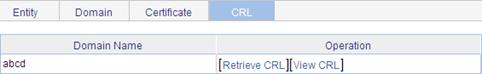
3. Click Retrieve CRL to retrieve the CRL of a domain.
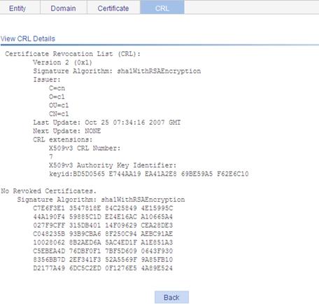
4. Click View CRL for the domain to display the contents of the CRL.
PKI configuration example
Network requirements
As shown in Figure 55, configure the AP working as the PKI entity, so that:
· The AP submits a local certificate request to the CA server, which runs the RSA Keon software.
· The AP retrieves CRLs for certificate verification.
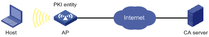
Configuring the CA server
1. Create a CA server named myca:
In this example, you must first configure the basic attributes of Nickname and Subject DN on the CA server: the nickname is the name of the trusted CA, and the subject DN is the DN attributes of the CA, including the common name, organization unit, organization, and country. Leave the default values of the other attributes.
2. Configure extended attributes:
After you configure the basic attributes, perform configuration on the Jurisdiction Configuration page of the CA server. This includes selecting the proper extension profiles, enabling the SCEP autovetting function, and adding the IP address list for SCEP autovetting.
3. Configure the CRL publishing behavior:
After you complete the configuration, perform CRL related configurations.
In this example, select the local CRL publishing mode of HTTP and set the HTTP URL to http://4.4.4.133:447/myca.crl.
After the configuration, make sure the system clock of the device and that of the CA are synchronized, so that the device can request certificate correctly.
Configuring the AP
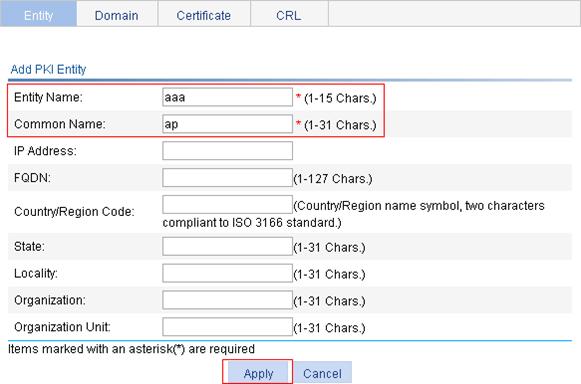
1. Create a PKI entity:
a. From the navigation tree, select Authentication > Certificate Management.
The PKI entity list page is displayed by default.
b. Click Add.
c. Enter aaa as the PKI entity name, enter ap as the common name, and click Apply.
Figure 56 Creating a PKI entity
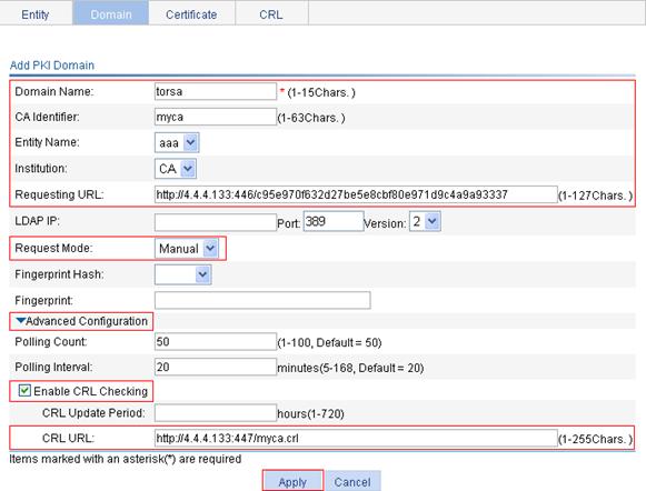
2. Create a PKI domain:
a. Click the Domain tab.
b. Click Add.
The page in Figure 57 appears.
c. In the upper area of the page, enter torsa as the PKI domain name, enter myca as the CA identifier, select aaa as the local entity, select CA as the authority for certificate request, enter http://4.4.4.133:446/c95e970f632d27be5e8cbf80e971d9c4a9a93337 as the URL for certificate request (the URL must be in the format of http://host:port/Issuing Jurisdiction ID, where Issuing Jurisdiction ID is the hexadecimal string generated on the CA), and select Manual as the certificate request mode.
d. Click the expansion button before Advanced Configuration to display the advanced configuration items.
e. In the advanced configuration area, click the Enable CRL Checking box, and enter http://4.4.4.133:447/myca.crl as the CRL URL.
f. Click Apply.
A dialog box appears, asking "Fingerprint of the root certificate not specified. No root certificate validation will occur. Continue?"
g. Click OK.
Figure 57 Creating a PKI domain
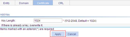
3. Generate an RSA key pair:
a. Click the Certificate tab.
b. Click Create Key.
c. Enter 1024 as the key length, and click Apply.
Figure 58 Generating an RSA key pair
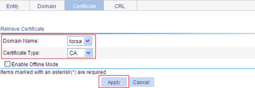
4. Retrieve the CA certificate:
a. Click the Certificate tab.
b. Click Retrieve Cert.
c. Select torsa as the PKI domain, select CA as the certificate type, and click Apply.
Figure 59 Retrieving the CA certificate
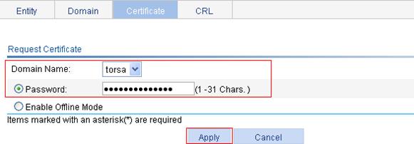
5. Request a local certificate:
a. Click the Certificate tab.
b. Click Request Cert.
c. Select torsa as the PKI domain, select Password, and enter challenge-word as the password.
d. Click Apply.
The system displays "Certificate request has been submitted."
e. Click OK to confirm.
Figure 60 Requesting a local certificate
6. Retrieve the CRL:
a. Click the CRL tab.
b. Click Retrieve CRL of the PKI domain of torsa.
Verifying the configuration
After the configuration, you can select Certificate Management > Certificate from the navigation tree to display detailed information about the retrieved CA certificate and local certificate, or select Certificate Management > CRL from the navigation tree to display detailed information about the retrieved CRL.
Configuration guidelines
When you configure PKI, follow these guidelines:
· Make sure the clocks of entities and the CA are synchronous. Otherwise, the validity periods of certificates are abnormal.
· The Windows 2000 CA server has some restrictions on the data length of a certificate request. If the PKI entity identity information in a certificate request goes beyond a certain limit, the server does not respond to the certificate request.
· The SCEP plug-in is required when you use the Windows Server as the CA. In this case, specify RA as the authority for certificate request when you configure the PKI domain.
· The SCEP plug-in is not required when you use the RSA Keon software as the CA. In this case, specify CA as the authority for certificate request when you configure the PKI domain.