- Table of Contents
- Related Documents
-
| Title | Size | Download |
|---|---|---|
| 03-Summary | 1.46 MB |
Displaying detailed information about WLAN services
Displaying statistics of WLAN service
Displaying connection history information of WLAN service
Displaying WLAN services bound to a radio
Displaying detailed radio information
Displaying client detailed information
Displaying RF ping information
Displaying beacon measurement reports
The interface types and output information vary by device model and radio type.
Device information
The device info page displays the following information:
· Device information
· System resource state
· Device interface information
· Recent system logs (at most five)
When you are logged in to the Web interface, you are placed on the Summary > Device Info page.
Figure 1 Device info page
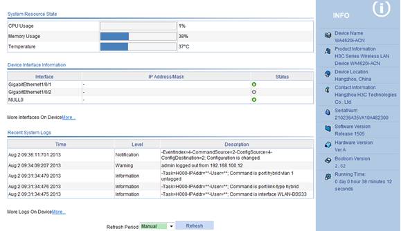
The information displayed on the device info page varies with devices.
Select a refresh mode in the Refresh Period list.
· If you select a specific refresh period (for example, 1 minute), the system periodically refreshes the Device Info page according to the selected refresh period.
· If you select Manual, click Refresh to refresh the page.
Device info
Table 1 Field description
|
Field |
Description |
|
Device Name |
Device model. |
|
Product Information |
Product information. |
|
Device Location |
Location of the device. To configure the device location information, select Device > SNMP > Setup; for more information, see "Configuring SNMP." |
|
Contact Information |
Contact information for device maintenance. To configure the contact information, select Device > SNMP > Setup; for more information, see "Configuring SNMP." |
|
SerialNum |
Serial number of the device. |
|
Software Version |
Software version of the device. |
|
Hardware Version |
Hardware version of the device. |
|
Bootrom Version |
Boot ROM version of the device. |
|
Running Time |
Running time after the latest boot of the device. |
System resource state
|
Field |
Description |
|
CPU Usage |
Real-time CPU usage. |
|
Memory Usage |
Real-time memory usage and the total memory size. Support for the display of the total memory size depends on the device model. |
|
Temperature |
Temperature of the device. |
Device interface information
|
Field |
Description |
|
Interface |
Interface name and interface number. |
|
IP Address/Mask |
IP address and mask of an interface. |
|
Status |
Interface status. ·
·
·
|
To know more information about device interfaces, click the More hyperlink under the Device Interface Information area to enter the Device > Interface page to view and operate the interfaces. For more information, see "Configuring interface management."
Recent system logs
|
Field |
Description |
|
Time |
Time when the system logs are generated. |
|
Level |
Level of the system logs. |
|
Description |
Contents of the system logs. |
To know more information about system logs, click the More hyperlink under the Recent System Operation Logs area to enter the Device > Syslog > Loglist page to view the logs. For more information, see "Configuring log management."
Displaying WLAN service
Select Summary > WLAN Service from the navigation tree and click the name of the specified WLAN service to view the detailed information, statistics, or connection history.
Displaying detailed information about WLAN services
Figure 2 shows the page that displays detailed information about clear-type WLAN services. Table 5 describes the fields on the page.
Figure 2 Displaying detailed information about clear-type WLAN services
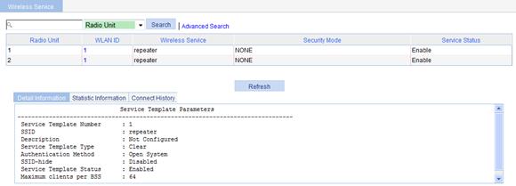
Table 5 Field description
|
Field |
Description |
|
Service Template Number |
Service template number. |
|
SSID |
Service set identifier (SSID) for the ESS. |
|
Description |
Description for the service template. If no description is configured, this field displays Not Configured. |
|
Service Template Type |
Service template type. |
|
Authentication Method |
Type of authentication used. WLAN service of the clear type only uses open system authentication. |
|
Beacon-measurement |
Enable—Enables beacon measurement. |
|
Beacon-measurement Interval |
Intervals (in seconds) at which beacon measurement requests are sent. |
|
Beacon-measurement Type |
Beacon measurement type: Passive, Active, or Beacon-table. |
|
SSID-hide |
· Disable—The SSID is advertised in beacon frames. · Enable—Disable the advertisement of the SSID in beacon frames. |
|
Service Template Status |
Status of service template: · Enable—Enable WLAN service. · Disable—Disable WLAN service. |
|
Maximum clients per BSS |
Maximum number of associated clients per BSS. |
Figure 3 shows the page that displays detailed information about crypto-type WLAN services. Table 6 describes the fields on the page.
Figure 3 Displaying detailed information about crypto-type WLAN services
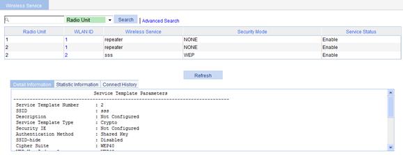
Table 6 Field description
|
Field |
Description |
|
Service Template Number |
Service template number. |
|
SSID |
SSID provided by the AP. |
|
Description |
Description for the service template. If no description is configured, this field displays Not Configured. |
|
Service Template Type |
Service template type. |
|
Security IE |
Security IE: WPA or WPA2(RSN). |
|
Authentication Method |
Authentication method: open system or shared key. |
|
Beacon-measurement |
Enable—Enables beacon measurement. |
|
Beacon-measurement Interval |
Intervals (in seconds) at which beacon measurement requests are sent. |
|
Beacon-measurement Type |
Beacon measurement type: Passive, Active, or Beacon-table. |
|
SSID-hide |
· Disable—The SSID is advertised in beacon frames. · Enable—Disable the advertisement of the SSID in beacon frames. |
|
WEP Key Index |
Key index to encrypt or decrypt frames. |
|
WEP Key Mode |
WEP key format: · HEX—Hexadecimal string. · ASCII—ASCII character string. |
|
WEP Key |
WEP key. |
|
Cipher Suite |
Cipher suite: AES-CCMP, TKIP, WEP40, WEP104, or WEP128. |
|
TKIP Countermeasure Time(s) |
TKIP countermeasure time in seconds. |
|
PTK Life Time(s) |
PTK lifetime in seconds. |
|
GTK Rekey |
GTK rekey configured. |
|
GTK Rekey Method |
GTK rekey method configured: packet based or time based. |
|
GTK Rekey Time(s) |
Time for GTK rekey in seconds. · If Time is selected, the GTK is refreshed after a specified period of time. · If Packet is selected, the GTK is refreshed after a specified number of packets are transmitted. |
|
PMF Status |
Status of management frame protection: · Disable—Management frame protection is disabled. · Optional—Management frame protection is enabled and all clients can associate with the AP. · Mandatory—Management frame protection is enabled and only clients supporting management frame protection can associate with the AP. |
|
Service Template Status |
Status of service template: · Enable—Enable WLAN service. · Disable—Disable WLAN service. |
|
Maximum clients per BSS |
Maximum number of associated clients per BSS. |
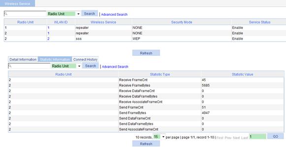
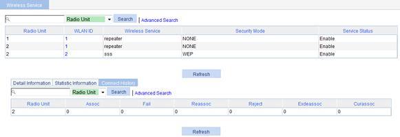
Displaying statistics of WLAN service
Figure 4 Displaying WLAN service statistics
Displaying connection history information of WLAN service
Figure 5 Displaying the connection history information of WLAN service
Displaying radio
Displaying WLAN services bound to a radio
Select Summary > Radio from the navigation tree, click the specified radio unit, and select the Wireless Service tab to view the WLAN services bound to the radio.
Figure 6 Displaying WLAN services bound to the radio
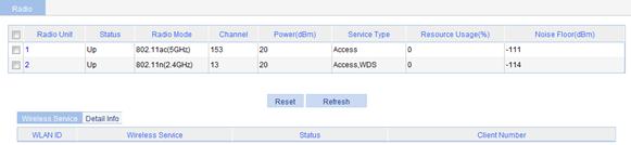
The Noise Floor item in the table indicates various random electromagnetic waves during the wireless communication. For the environment with a high noise floor, you can improve the signal-to-noise ratio (SNR) by increasing the transmit power or reducing the noise floor.
The Service Type item in the table has three options: None, Access, and Mesh.
Res Using Ratio represents the resource utilization of a radio within a certain period. For example, in a period of 10 seconds, if a radio has occupied the channel for five seconds, the resource utilization of the radio is 5 seconds divided by 10 seconds: 50%.
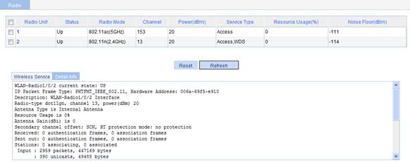
Displaying detailed radio information
Select Summary > Radio from the navigation tree, click the specified radio unit, and select the Detail Info tab to view the corresponding detailed information.
Figure 7 Displaying detailed radio information
Displaying WDS
Select Summary > WDS from the navigation tree to enter the WDS page.
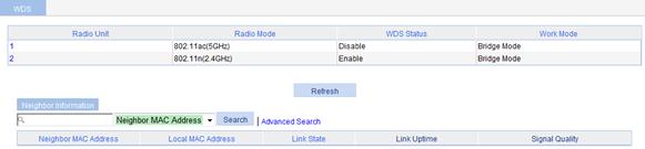
The AP can operate in two modes:
· Bridge mode—The AP operates in the network as a Layer 2 device.
· Route mode—The AP operates in the network as a Layer 3 device.
At present, the AP operates in bridge mode only.
Table 7 Field description
|
Field |
Description |
|
Neighbor MAC Address |
MAC address of the radio interface of the neighbor. |
|
Local MAC Address |
MAC address of the local radio interface. |
|
Link State |
Link state, which can be up, down, or processing. |
|
Link Uptime |
Up time of the current WDS link. |
|
Signal Quality |
|
Displaying client
Displaying client detailed information
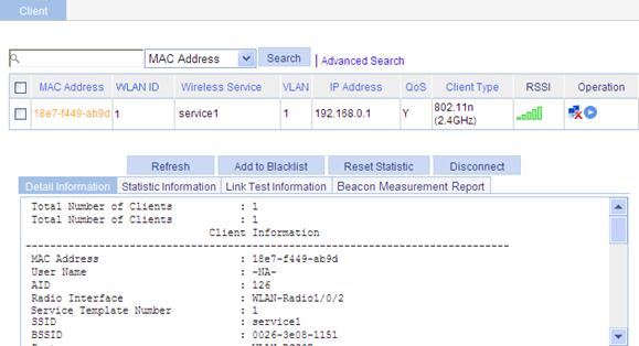
Select Summary > Client from the navigation tree to enter the Client page, click the Detail Information tab on the page, and click the name of the specified client to view the detailed information of the client.
The detailed information about a client is as shown in Figure 9. For the description of the fields in the client detailed information, see Table 8. For the description of the buttons on this page, see Table 9.
|
Field |
Description |
|
MAC Address |
MAC address of the client. |
|
User Name |
Username of the client: · The field is displayed as -NA- if the client adopts plain-text authentication or cipher-text authentication with no username. · The field is irrelevant to the portal authentication method. If the client uses the portal authentication method, the field does not display the portal username of the client. |
|
IP address |
IP address of the client. |
|
AID |
Association ID of the client. |
|
Radio Interface |
Radio interface associated with the client. |
|
Service Template Number |
Service template number of the client. |
|
SSID |
SSID associated with the client. |
|
BSSID |
Basic SSID. |
|
Port |
WLAN-DBSS interface associated with the client. |
|
VLAN |
Number of the VLAN interface to which the client belongs. |
|
State |
State of the client such as running. |
|
Power Save Mode |
Client’s power save mode: active or sleep. |
|
Wireless Mode |
Wireless mode such as 802.11a, 802.11b, 802.11g, 802.11an, 802.11gn, and 802.11ac. |
|
Channel Band-width |
Channel bandwidth, 20 MHz, 40 MHz, or 80 MHz. |
|
SM Power Save Enable |
SM Power Save enables a client to have one antenna in the active state, and others in sleep state to save power. · Enabled—SM Power Save is supported. · Disabled—SM Power Save is not supported. |
|
Short GI for 20MHz |
Whether the client supports short GI when its channel bandwidth is 20 MHz. |
|
Short GI for 40MHz |
Whether the client supports short GI when its channel bandwidth is 40 MHz. |
|
Short GI for 80MHz |
Whether the client supports short GI when its channel bandwidth is 80 MHz. |
|
Short GI for 160/80+80MHz |
Whether the client supports short GI when its channel bandwidth is 160/80+80 MHz. |
|
LDPC |
Whether LDPC is supported: · Not Supported. · Supported. |
|
STBC Tx Capability |
STBC transmission capability: · Not Supported. · Supported. The AP and a client negotiate the STBC transmission capability. The negotiation can succeed only when both the AP and client have STBC transmission capability. |
|
STBC Rx Capability |
STBC receive capability: · Not Supported. · Supported. The AP and a client negotiate the STBC receive capability. The negotiation can succeed only when both the AP and client have STBC receive capability. |
|
Support MCS Set |
MCS supported by the client. |
|
Support VHT-MCS and Nss Set |
VHT-MCS and NSS supported by the client. |
|
BLOCK ACK-TID |
BLOCK ACK is negotiated based on QoS priority ID: · OUT—Outbound direction. · IN—Inbound direction. · BOTH—Both directions. |
|
QoS Mode |
Whether the AP supports the WMM function. |
|
Listen Interval (Beacon Interval) |
How often the client wakes up to receive frames saved in the AP and is expressed in units of beacon interval. |
|
RSSI |
Received signal strength indication. This value indicates the client signal strength detected by the AP. |
|
Rx/Tx Rate |
Transmission/reception rate of packets (including data, management and control packets). |
|
Client Type |
Client type such as RSN, WPA, or Pre-RSN. |
|
Authentication Method |
Authentication method such as open system or shared key. |
|
AKM Method |
AKM suite used such as Dot1X or PSK. |
|
Key Derivation |
Key derivation type: · SHA1—Uses the HMAC-SHA1 hash algorithm. · SHA256—Uses the HMAC-SHA256 hash algorithm. · -NA-—No key derivation algorithm is involved for the authentication type. |
|
4-Way Handshake State |
Four-way handshake state: · IDLE—Displayed in initial state. · PTKSTART—Displayed when the 4–way handshake is initialized. · PTKNEGOTIATING—Displayed after the third message was sent. · PTKINITDONE—Displayed when the 4-way handshake is successful. |
|
Group Key State |
Group key state: · IDLE—Displayed in initial state. · REKEYNEGOTIATE—Displayed after the initial message is sent to the client. · REKEYESTABLISHED—Displayed when re-keying is successful. |
|
Encryption Cipher |
Encryption cipher: clear or crypto. |
|
PMF Status |
Management frame protection state: · Active. · Inactive. · -NA-—No PMF is involved for the authentication type. |
|
Roam Status |
Roaming status: Normal. |
|
Roam Count |
Roaming count of the client. |
|
Up Time |
Time for which the client has been associated with the AP. |
|
Field |
Description |
|
Refresh |
Refresh the current page. |
|
Add to Blacklist |
Add the selected client to the static blacklist, which you can display by selecting Security > Filter from the navigation tree. |
|
Reset Statistic |
Clear statistics of the specified client. |
|
Disconnect |
Log off the selected client. |
Displaying client statistics
Select Summary > Client from the navigation tree to enter the Client page, click the Statistic Information tab on the page, and click the name of the specified client to view the statistics of the client.
Figure 10 Displaying client statistics
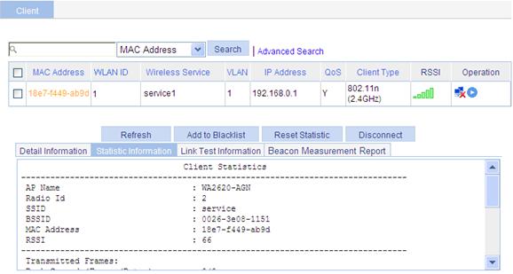
To view the IP address of the client, enable the ARP snooping function in system view at the CLI. By default, the ARP snooping function is disabled, and NA is displayed in the IP Address column.
|
Field |
Description |
|
AP Name |
Name of the associated AP. |
|
Radio Id |
ID of the radio interface associated with the client. |
|
SSID |
SSID associated with the client. |
|
BSSID |
Basic SSID. |
|
MAC Address |
MAC Address of the client. |
|
RSSI |
Received signal strength indication. This value indicates the client signal strength detected by the AP. |
|
Transmitted Frames |
Number of transmitted frames. |
|
Back Ground(Frames/Bytes) |
Statistics of background traffic, in frames or in bytes. |
|
Back Ground(Frames/Bytes) |
Statistics of background traffic, in frames or in bytes. |
|
Best Effort(Frames/Bytes) |
Statistics of best effort traffic, in frames or in bytes. |
|
Video(Frames/Bytes) |
Statistics of video traffic, in frames or in bytes. |
|
Voice(Frames/Bytes) |
Statistics of voice traffic, in frames or in bytes. |
|
Received Frames |
Number of received frames. |
|
Discarded Frames |
Number of discarded frames. |
Displaying RF ping information
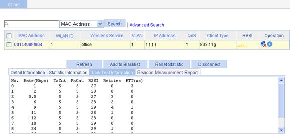
Radio Frequency Ping (RF Ping) is a ping function performed on wireless links. This function enables you to get the connection information between the AP and its associated clients, such as signal strength, packet re-transmission attempts, and Round-trip Time (RTT).
Select Summary > Client from the navigation tree to enter the Client page, click the Link Test Information tab on the page, and click the name of the specified client to view the link test information of the client. For the description of the fields in the client link test information, see Table 11.
Figure 11 Viewing link test information
|
Field |
Description |
|
No./MCS |
· Rate number for a non-802.11n client. · MCS value for an 802.11n client. |
|
Rate(Mbps) |
Rate at which the radio interface sends wireless ping frames. |
|
TxCnt |
Number of wireless ping frames that the radio interface sent. |
|
RxCnt |
Number of wireless ping frames that the radio interface received from the client. |
|
RSSI |
Received signal strength indication. This value indicates the client signal strength detected by the AP. |
|
Retries |
Total number of retransmitted ping frames. |
|
RTT(ms) |
Round trip time. |
Displaying beacon measurement reports
1. Select Summary > Client from the navigation tree.
2. Click the Beacon Measurement Report tab.
3. Click the name of the specified client to view the beacon measurement reports of the client.
Figure 12 Displaying beacon measurement reports
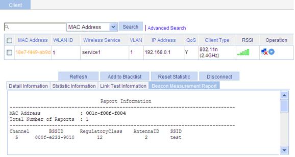
Table 12 Field description
|
Field |
Description |
|
MAC Address |
MAC address of the client. |
|
Total Number of Reports |
Number of beacon measurement reports. |
|
Channel |
Channel number. |
|
BSSID |
Basic service set identifier. |
|
Regulatory Class |
Regulatory class: 12 or 5. For more information, see the 802.11k protocols. |
|
Antenna ID |
Antenna identifier. |
|
SSID |
Service set identifier. |