- Table of Contents
- Related Documents
-
| Title | Size | Download |
|---|---|---|
| 04-Device | 1.11 MB |
Configuring basic device settings·
Configuring Web idle timeout period
Setting the time zone and daylight saving time
Setting buffer capacity and refresh interval
Displaying interface information and statistics
Interface management configuration example
Feature and hardware compatibility
Switching to the management level
SNMPv1/v2c configuration example
Configuring the AP (SNMP agent)
The device basic information feature enables you to do the following:
· Set the system name of the device.
The configured system name appears at the top of the navigation bar.
· Set the idle timeout period for a logged-in user.
The system logs an idle user off the Web for security purpose after the configured period.
Configuring system name
1. Select Device > Basic from the navigation tree to enter the system name page, as shown in Figure 1.
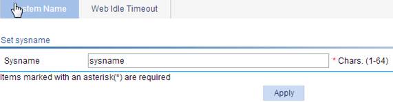
2. Set the system name.
3. Click Apply.
Configuring Web idle timeout period
1. Select Device > Basic from the navigation tree
2. Click the Web Idle Timeout tab and enter the Web idle timeout page, as shown in Figure 2.
Figure 2 Configuring Web idle timeout period
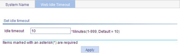
3. Set the Web idle timeout period for a logged-in user.
4. Click Apply.
Software upgrade
|
|
CAUTION: A software upgrade takes some time. Avoid performing any operation on the Web interface during the upgrading procedure. Otherwise, the upgrade operation may be interrupted. |
A boot file, also known as the system software or device software, is an application file used to boot the device. Software upgrade allows you to get a target application file from the local host and set the file as the boot file to be used at the next reboot. In addition, you can select whether to reboot the device to bring the upgrade software into effect.
After you get the target application file from the local host, you need to keep the original file name.
1. Select Device > Device Maintenance from the navigation tree to enter the Software Upgrade tab.
Figure 3 Software upgrade configuration page
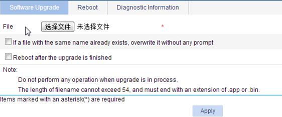
2. Configure software upgrade parameters as described in Table 1.
3. Click Apply.
|
Item |
Description |
|
File |
Specify the path of the local application file. Make sure the file has the extension .app or .bin. |
|
If a file with the same name already exists, overwrite it without any prompt |
Specify whether to overwrite the file with the same name. If you do not select the option and there is another file with the same name, the system prompts "The file has existed," and you cannot upgrade the software. |
|
Reboot after the upgrade is finished. |
Specify whether to reboot the device to make the upgraded software take effect after the application file is uploaded. |
Reboot
|
|
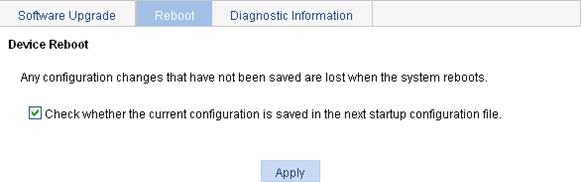
CAUTION: Before you reboot the device, save the configuration. Otherwise, all unsaved configurations are lost after device reboot. |
To reboot the device:
1. Select Device > Device Maintenance from the navigation tree.
2. Click Device Reboot.
3. Do one of the following:
¡ Clear the box before "Check whether the current configuration is saved in the next startup configuration file".
¡ Keep the box selection for "Check whether the current configuration is saved in the next startup configuration file."
4. Click Apply.
A confirmation dialog box appears.
5. Click OK.
¡ If you select the box before "Check whether the current configuration is saved in the next startup configuration file", the system checks the configuration before rebooting the device. If the check succeeds, the system reboots the device. If the check fails, the system displays a dialog box to inform you that the current configuration and the saved configuration are inconsistent, and does not reboot the device. In this case, you must manually save the current configuration before you can reboot the device.
¡ If you do not select the box, the system reboots the device directly.
Log in again to the Web interface after the device reboots.
Diagnostic information
Each functional module has its own running information. Generally, you need to view the output for each module one by one. To get as much information as possible in one operation during daily maintenance or when system failure occurs, the device supports generating diagnostic information. When you perform the diagnostic information generation operation, the system saves the running statistics of multiple functional modules to a file named default.diag. Then you can locate problems faster by checking this file.
1. Select Device > Device Maintenance from the navigation tree.
2. Click the Diagnostic Information tab.
Figure 5 Diagnostic information
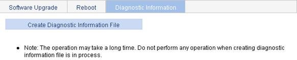
3. Click Create Diagnostic Information File.
The system begins to generate the diagnostic information file.
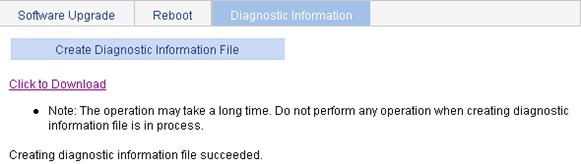
4. Click Click to Download.
The File Download dialog box appears.
5. Select to open this file or save this file to the local host.
Figure 6 The diagnostic information file is created
The generation of the diagnostic file will take a period of time. During this process, do not perform any operation on the Web page.
To view this file after the diagnostic file is generated successfully, select Device > File Management, or download this file to the local host. For more information, see "Managing files."
You must configure a correct system time so that the device can work with other devices properly. System time allows you to display and set the device system time, system zone, and daylight saving time on the Web interface.
The device supports setting system time through manual configuration and automatic synchronization of NTP server time.
An administrator cannot keep time synchronized among all the devices within a network by changing the system clock on each device, because this is a huge amount of workload and cannot guarantee clock precision.
Defined in RFC 1305, the NTP synchronizes timekeeping among distributed time servers and clients.
NTP can keep consistent timekeeping among all clock-dependent devices within the network and ensure a high clock precision so that the devices can provide diverse applications based on consistent time.
Displaying the system time
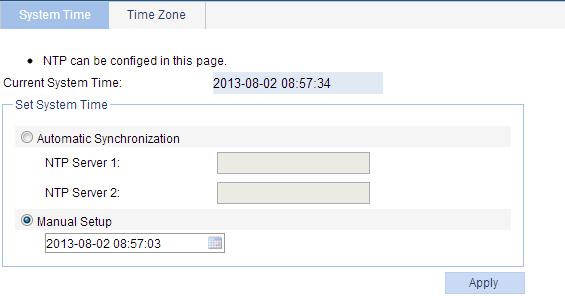
Select Device > System Time from the navigation tree to enter the System Time tab, as shown in Figure 7.
Figure 7 System time configuration page
Configuring the system time
1. Select Device > System Time from the navigation tree.
2. Configure the system time as described in Table 2 .
3. Click Apply.
|
Item |
Description |
|
|
Automatic Synchronization |
NTP Server 1. |
Enable clock automatic synchronization with an NTP server. You can specify two NTP servers by entering their IP addresses. NTP Server 1 is the primary and NTP Server 2 is the secondary.
· With automatic synchronization configured, the device periodically synchronizes its time with the NTP server. If the synchronization fails, the system uses the manually configured time. After the synchronization recovers, the system uses the synchronized time. · The IP address of an NTP server is a host address, and cannot be a broadcast or a multicast address, or the IP address of the local clock. · If the system time of the NTP server is ahead of the system time of the device, and the difference between them exceeds the Web idle time specified on the device, all online Web users are logged out because of timeout. |
|
NTP Server 2. |
||
|
Manual Setup |
Set the system time manually. You can type the system date and time in the text box, or select the date and time in the calendar as follows: · Click Today. The date in the calendar becomes the local date, and the time in the calendar does not change. · Select the year, month, date, and time. · Click OK. |
|
Figure 8 Calendar page

Setting the time zone and daylight saving time
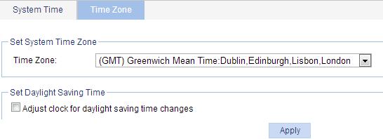
1. Select Device > System Time from the navigation tree.
2. Click the Time Zone tab.
The page for setting the time zone appears.
Figure 9 Setting the time zone
3. Select the time zone and daylight saving time as described in Table 3.
4. Click Apply.
|
Item |
Description |
|
Time Zone |
Set the time zone for the system. |
|
Adjust clock for daylight saving time changes |
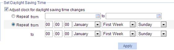
Adjust the system clock for daylight saving time changes, which means adding one hour to the current system time. Click Adjust clock for daylight saving time changes to expand the option, as shown in Figure 10. You can configure the daylight saving time changes in the following ways: Specify that the daylight saving time starts on a specific date and ends on a specific date. The time range must be greater than one day and smaller than one year. For example, configure the daylight saving time to start on August 1st, 2006 at 06:00:00 a.m., and end on September 1st, 2006, at 06:00:00 a.m.. Specify that the daylight saving time starts and ends on the corresponding specified days every year. The time range must be greater than one day and smaller than one year. For example, configure the daylight saving time to start on the first Monday in August at 06:00:00 a.m., and end on the last Sunday in September at 06:00:00 a.m.. |
Figure 10 Setting the daylight saving time
System logs record network and device information, including running status and configuration changes. With system logs, administrators can take corresponding actions against network problems and security problems.
The system sends system logs to the following destinations:
· Console.
· Monitor terminal, a terminal that has logged in to the device through the AUX, VTY, or TTY user interface.
· Log buffer.
· Loghost.
· Web interface.
Displaying syslogs
1. Select Device > Syslog from the navigation tree to enter the syslog display page, as shown in Figure 11.
You can click Reset to clear all system logs saved in the log buffer. You can click Refresh to manually refresh the page, or you can set the refresh interval on the Log Setup page to enable the system to automatically refresh the page periodically. For more information, see "Setting buffer capacity and refresh interval."
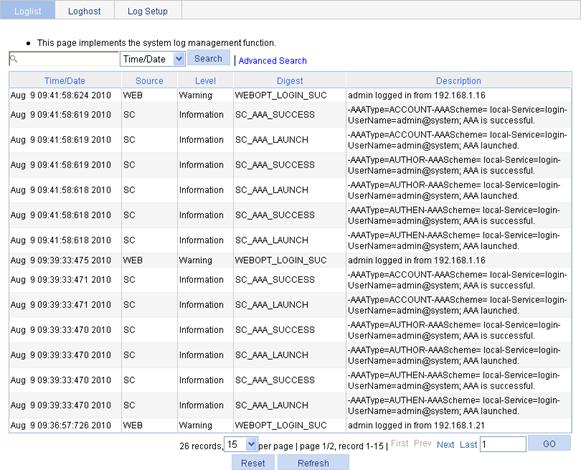
2. View system logs.
Table 4 Field description
|
Field |
Description |
|
Time/Date |
Displays the time/date when the system log was generated. |
|
Source |
Displays the module that generated the system log. |
|
Level |
Displays the severity level of the system log. The information is classified into eight levels by severity: · Emergency—The system is unusable. · Alert—Action must be taken immediately. · Critical—Critical condition. · Error—Error condition. · Warning—Warning condition. · Notification—Normal but significant condition. · Information—Informational message. · Debug—Debug-level message. |
|
Digest |
Displays the brief description of the system log. |
|
Description |
Displays the content of the system log. |
Setting the log host
You can set the loghost on the Web interface to enable the system to output syslogs to the log host. You can specify up to four log hosts.
To set the log host:
1. Select Device > Syslog from the navigation tree
2. Click the Loghost tab to enter the loghost configuration page, as shown in Figure 12.
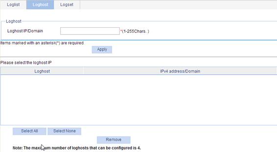
3. Set the log host as described in Table 5.
4. Click Apply.
Table 5 Loghost configuration items
|
Item |
Description |
|
Loghost IP/Domain |
Set the IP address, or domain name of the loghost. You can specify up to four log hosts. |
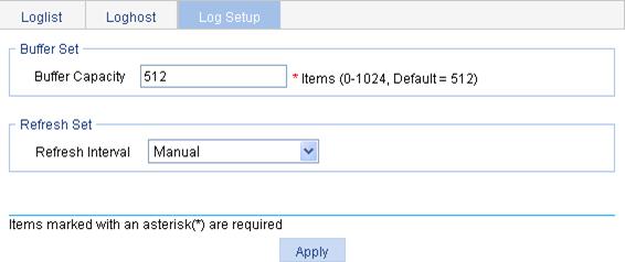
Setting buffer capacity and refresh interval
1. Select Device > Syslog from the navigation tree.
2. Click the Log Setup tab.
The syslog configuration page appears.
Figure 13 Setting system logs related parameters
3. Set the buffer capacity and refresh interval as described in Table 6.
4. Click Apply.
|
Item |
Description |
|
Buffer Capacity |
Set the number of logs that can be stored in the log buffer. |
|
Refresh Interval |
Set the log refresh interval. You can select manual refresh or automatic refresh: · Manual—Click Refresh to view latest log information. · Automatic—Select to refresh the Web interface every 1 minute, 5 minutes, or 10 minutes. |
Administrators can back up, restore, save, or reset the device configuration.
Backing up the configuration
Configuration backup provides the following functions:
· Open and view the configuration file (.cfg or .xml file) for the next startup.
· Back up the configuration file (.cfg or .xml file) for the next startup to the host of the administrator.
|
|
IMPORTANT: H3C recommends backing up both the .cfg and .xml configuration files. If you back up only the .cfg configuration file, some configuration information might not be restored when, for example, the configuration is mistakenly removed. |
To back up the configuration:
1. Select Device > Configuration from the navigation tree.
The Backup page appears.
Figure 14 Backing up the configuration
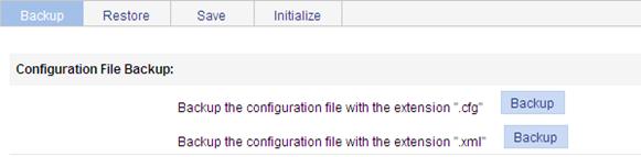
2. Click the upper Backup button.
A file download dialog box appears.
3. Select to view the .cfg file or to save the file to the local host.
4. Click the lower Backup button.
A file download dialog box appears.
5. Select to view the .xml file or to save the file to the local host.
Restoring the configuration
Configuration restore provides the following functions:
· Upload the .cfg file on the host of the administrator to the device for the next startup.
· Upload the .xml file on the host of the administrator to the device for the next startup, and delete the previous .xml configuration file that was used for the next startup.
The restored configuration takes effect at the next boot of the device.
To restore the configuration:
1. Select Device > Configuration from the navigation tree.
2. Click the Restore tab to enter the configuration restore page.
Figure 15 Restoring the configuration
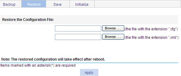
3. Click the upper Browse button.
The file upload dialog box appears.
4. Select the .cfg file to be uploaded, and then click OK.
5. Click the lower Browse button.
The file upload dialog box appears.
6. Select the .xml file to be uploaded, and then click OK.
7. Click Apply.
Saving the configuration
The save configuration module allows administrators to save the running configuration to the configuration file (.cfg or .xml file) to be used at the next startup.
Only one administrator can save the configuration at a moment, and saving the configuration takes some time. If one administrator saves the configuration while the system is saving the configuration as required by another administrator, the system prompts the second administrator to try later.
This module supports saving the configuration in either of the following two modes: fast or common.
Saving the configuration in fast mode
To save the configuration in fast mode, click the Save button at the upper right of the auxiliary area.
Figure 16 Saving the configuration
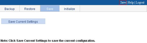
Saving the configuration in common mode
1. Select Device > Configuration from the navigation tree.
2. Click the Save tab, as shown in Figure 16.
3. Click Save Current Settings.
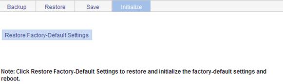
Resetting the configuration
This operation restores the device's factory defaults, deletes the current configuration file, and reboots the device.
To reset the configuration:
1. Select Device > Configuration from the navigation tree.
2. Click the Initialize tab to enter the initialize confirmation page.
3. Click Restore Factory-Default Settings to restore the factory defaults.
Figure 17 Resetting the configuration
The file management function allows you to manage the files on the storage media.
Displaying files
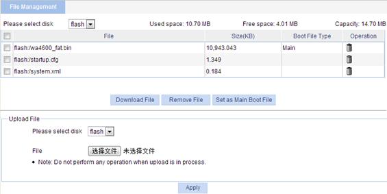
1. Select Device > File Management from the navigation tree to enter the file management page.
Figure 18 File management page
|
|
NOTE: Support for the file information displayed on the page varies by device model. |
2. Select a medium from the Please select disk list at the top of the page.
Two categories of information are displayed:
¡ Medium Information, including the used space, free space, and the capacity of the medium.
¡ File information, including all files on the medium, the file sizes, and the boot file types (Main or Backup). The boot file type is only displayed for an application file (with the extension .bin or .app) that will be used as the main or backup boot file.
Downloading a file
1. Select Device > File Management from the navigation tree to enter the file management page (see Figure 18).
2. From the Please select disk list, select the medium where the file to be downloaded resides.
3. Select the file from the list.
Only one file can be downloaded at a time.
4. Click the Download File button.
The File Download dialog box appears.
5. Open the file or save the file to a specified path.
Uploading a file
|
|
IMPORTANT: Uploading a file takes some time. H3C does not recommend performing any operation on the Web interface during the upload. |
To upload a file:
1. Select Device > File Manage from the navigation tree to enter the file management page (see Figure 18).
2. In the Upload File area, select the medium for saving the file from the Please select disk list.
3. Click Browse to navigate to the file to be uploaded.
4. Click Apply.
Removing a file
1. Select Device > File Management from the navigation tree to enter the file management page (see Figure 18).
2. Do one of the following :
¡ Click the ![]() icon of a file to remove the file.
icon of a file to remove the file.
¡ Select a file from the file list and click Remove File.
To remove multiple files, repeat step 2, or select the files from the file list and click Remove File.
Specifying the main boot file
1. Select Device > File Management from the navigation tree to enter the file management page (see Figure 18).
2. From the Please select disk list, select the medium that holds the application file to be used as the main boot file.
3. Select the application file (with the extension .bin or .app) from the file list.
4. Click Set as Main Boot File.
An interface is the point of interaction or communication used for exchanging data between entities. There are two types of interfaces: physical and logical. A physical interface refers to an interface that physically exists as a hardware component. An example is an Ethernet interface. A logical interface refers to an interface that can implement data switching but does not exist physically. A logical interface must be created manually. An example is a VLAN interface.
You can use the interface management feature on the Web-based configuration interface to manage the following types of interfaces:
· Layer 2 Ethernet interface—Physical interface operating on the data link layer for forwarding Layer 2 protocol packets.
· WLAN radio interface—Physical interface used for providing wireless access service. A WLAN radio interface can be bound with a WLAN-BSS interface, or a WLAN Ethernet interface.
· Loopback interface—Software-only virtual interface. The physical layer state and link layer protocols of a loopback interface are always up unless the loopback interface is manually shut down. You can enable routing protocols on a loopback interface, and a loopback interface can send and receive routing protocol packets. When you assign an IPv4 address to a loopback interface, the mask of the address must be 32-bit long.
· Null interface—Software-only virtual interface. A null interface is always up. A null interface does not forward packets, and you cannot configure an IP address or enable a link-layer protocol on a null interface. With a null interface specified as the next hop of a static route to a specific network segment, any packets routed to the network segment are dropped. The null interface provides a simpler way to filter packets than an ACL. You can filter unwanted traffic by transmitting it to a null interface instead of applying an ACL.
· VLAN interface—Virtual Layer 3 interface used for Layer 3 communications between VLANs. A VLAN interface corresponds to a VLAN. You can assign an IP address to a VLAN interface and specify it as the gateway of the corresponding VLAN to forward traffic destined for an IP network segment different from that of the VLAN.
· BAGG interface—Also known as "Layer 2 aggregate interface." When you create a Layer 2 aggregate interface, the system automatically creates a Layer 2 aggregation group numbered the same. You can assign only Layer 2 Ethernet interfaces to a Layer 2 aggregation group.
· Dialer interface—Logical interface for dialup services. You can bind a physical interface (such as a serial, BRI, or Async interface) to a dialer interface to inherit the configuration information of the dialer interface. The baud rate of a dialer interface is fixed at 64000 bps.
· Cellular-Ethernet interface—Physical 3G/4G modem interface used as an uplink interface for LTE networks.
Displaying interface information and statistics
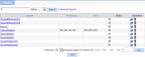
1. Select Device > Interface from the navigation tree to enter the page shown in Figure 19.
The page displays the interfaces' names, IP addresses, masks, and status.
Figure 19 Interface management page
|
|
NOTE: Support for the interface information displayed on the page varies by device model. |
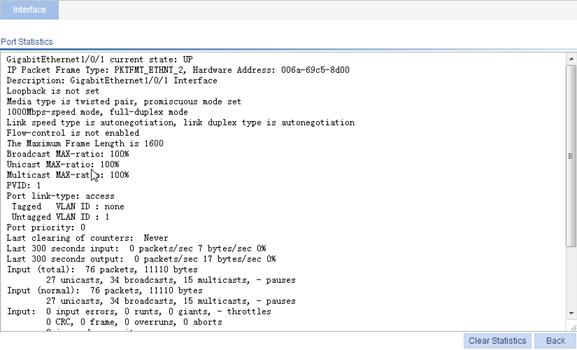
2. Click an interface name in the Name column to display the statistics of that interface.
Figure 20 Statistics on an interface
Creating an interface
1. Select Device > Interface from the navigation tree to enter the page shown in Figure 19.
2. Click Add to enter the page for creating an interface.
The page for creating an interface appears.
Figure 21 Creating an interface
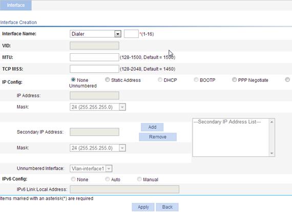
3. Configure the interface as described in Table 7.
4. Click Apply.
|
Item |
Description |
|
Interface Name |
Set the type and number of a logical interface. |
|
VID |
If you are creating a Layer 3 Ethernet subinterface, set the VLANs associated with the subinterface. This parameter is available only for Layer 3 Ethernet subinterfaces. This configuration item is not configurable because the device does not support Layer 3 Ethernet subinterfaces. |
|
MTU |
Set the MTU of the interface. |
|
TCP MSS |
Set the maximum segment size for TCP on the interface. |
|
IP Config |
Set the way for the interface to obtain an IP address: · None—Select this option if you do not want to assign an IP address to the interface. · Static Address—Select the option to manually assign an IP address and mask to the interface. If you select this option, you must set the IP Address and Mask fields. · DHCP—Select the option for the interface to obtain an IP address through DHCP automatically. · BOOTP—Select the option for the interface to obtain an IP address through BOOTP automatically. · PPP Negotiate—Select the option for the interface to obtain an IP address through PPP negotiation. · Unnumbered—Select this option to borrow the IP address of another interface on the same device for the interface. If you select this option, you must select the interface whose IP address you want to borrow in the Unnumbered Interfaces list. Support for the way of obtaining an IP address depends on the interface type. |
|
IP Address/Mask |
After you select the Static Address option for the IP Config configuration item, you must set the primary IP address and mask, and secondary IP addresses and masks for the interface. · The primary and secondary IP addresses cannot be 0.0.0.0. · For a loopback interface, the mask is fixed to 32 bits and is not configurable. · A fat AP supports only one secondary IP address. |
|
Secondary IP Address/Mask |
|
|
Unnumbered Interface |
If you select the Unnumbered option as the way for the interface to get an IP address, you must set the interface whose IP address is to be borrowed. |
|
IPv6 Config |
Set the way for the interface to obtain an IPv6 link-local address, including: · None—Select this option if you do not want to assign an IPv6 link-local address to the interface. · Auto—Select this option for the system to automatically assign an IPv6 link-local address to the interface. · Manual—Select this option to manually assign an IPv6 link-local address to the interface. If you select this option, you must set the IPv6 Link Local Address field. |
|
IPv6 Link Local Address |
If you select the Manual option as the way for the interface to get an IPv6 link-local address, you must set an IPv6 link-local address for the interface. |
Modifying a Layer 2 interface
1. Select Device > Interface from the navigation tree to enter the page shown in Figure 19.
2.
Click the ![]() icon for a Layer 2 interface.
icon for a Layer 2 interface.
The page for modifying a Layer 2 physical interface appears.
Figure 22 Modifying a Layer 2 physical interface
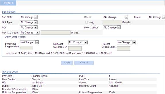
3. Modify the Layer 2 physical interface as described in Table 8.
4. Click Apply.
|
Item |
Description |
|
Port State |
Enable or disable the interface. In some cases, modification to the interface parameters does not take effect immediately. You must shut down and then bring up the interface to make the modification work. |
|
Speed |
Set the transmission rate of the interface. Available options include: · 10—10 Mbps. · 100—100 Mbps. · 1000—1000 Mbps. · Auto—Auto-negotiation. · Auto 10—The auto-negotiation rate of the interface is 10 Mbps. · Auto 100—The auto-negotiation rate of the interface is 100 Mbps. · Auto 1000—The auto-negotiation rate of the interface is 1000 Mbps. · Auto 10 100—The auto-negotiation rate of the interface is 10 Mbps or 100 Mbps. · Auto 10 1000—The auto-negotiation rate of the interface is 10 Mbps or 1000 Mbps. · Auto 100 1000—The auto-negotiation rate of the interface is 100 Mbps or 1000 Mbps. · Auto 10 100 1000—The auto-negotiation rate of the interface is 10 Mbps, 100 Mbps or 1000 Mbps. |
|
Duplex |
Set the duplex mode of the interface: · Auto—Auto-negotiation. · Full—Full duplex. · Half—Half duplex. |
|
Link Type |
Set the link type of the current interface, which can be access, hybrid, or trunk. For more information, see Table 9. To change the link type of a port from trunk to hybrid or vice versa, you must first set its link type to access. |
|
PVID |
Set the port VLAN ID of the hybrid or trunk port. The trunk ports at the two ends of a link must have the same PVID. |
|
MDI |
Set the MDI mode for the interface. Two types of Ethernet cables can be used to connect Ethernet devices: crossover cable and straight-through cable. To accommodate these two types of cables, an Ethernet interface on the device can operate in one of the following three MDI modes: · Across mode. · Normal mode. · Auto mode. An Ethernet interface is composed of eight pins. By default, each pin has its particular role. For example, pin 1 and pin 2 are used for transmitting signals, while pin 3 and pin 6 are used for receiving signals. You can change the pin roles through setting the MDI mode. · In across mode, the default pin roles are kept, that is, pin 1 and pin 2 for transmitting signals, and pin 3 and pin 6 for receiving signals. · In auto mode, the pin roles are determined through auto negotiation. · In normal mode, pin 1 and pin 2 are used for receiving signals while pin 3 and pin 6 are used for transmitting signals. To enable normal communication, connect the local transmit pins to the remote receive pins, and configure the MDI mode depending on the cable types. · Generally, the auto mode is recommended. The other two modes are useful only when the device cannot determine the cable types. · When you use straight-through cables, the local MDI mode must be different from the remote MDI mode. · When you use crossover cables, the local MDI mode must be the same as the remote MDI mode, or the MDI mode of at least one end must be set to auto. |
|
Flow Control |
Enables or disables flow control on the interface. After flow control is enabled on both ends, if there is traffic congestion on the device on the local end, it sends information to notify the peer end to stop sending packets temporarily. Upon receiving the information, the peer end stops sending packets. This is used to avoid packet loss. Flow control can be realized only when it is enabled on both ends. |
|
Max MAC Count |
Set the maximum number of MAC addresses the interface can learn. Available options include: · User Defined—Select this option to set the limit manually. · No Limited—Select this option to set no limit. |
|
Broadcast Suppression |
Set broadcast suppression. You can suppress broadcast traffic by percentage or by PPS as follows: · ratio—Sets the maximum percentage of broadcast traffic to the total transmission capability of an Ethernet interface. When you select this option, you must enter a percentage in the box below. · pps—Sets the maximum number of broadcast packets that can be forwarded on an Ethernet interface per second. When you select this option, you must enter a number in the box below. |
|
Multicast Suppression |
Set multicast suppression. You can suppress multicast traffic by percentage or by PPS as follows: · ratio—Sets the maximum percentage of multicast traffic to the total transmission capability of an Ethernet interface. When you select this option, you must enter a percentage in the box below. · pps—Sets the maximum number of multicast packets that can be forwarded on an Ethernet interface per second. When you select this option, you must enter a number in the box below. |
|
Unicast Suppression |
Set unicast suppression. You can suppress unicast traffic by percentage or by PPS as follows: · ratio—Sets the maximum percentage of unicast traffic to the total transmission capability of an Ethernet interface. When you select this option, you must enter a percentage in the box below. · pps—Sets the maximum number of unicast packets that can be forwarded on an Ethernet interface per second. When you select this option, you must enter a number in the box below. |
|
Link type |
Description |
|
Access |
An access port can belong to only one VLAN. Usually it is used to connect a user device. |
|
Hybrid |
A hybrid port can be assigned to multiple VLANs to receive and send packets for them and allows packets of multiple VLANs to pass through untagged. You can use hybrid ports to connect network devices and user devices. |
|
Trunk |
A trunk port can be assigned to multiple VLANs to receive and send packets for them, but allows only packets of the default VLAN to pass through untagged. Usually, you can use trunk ports to connect network devices. |
Modifying a Layer 3 interface
1. Select Device > Interface from the navigation tree to enter the page shown in Figure 19.
2.
Click the ![]() icon for a Layer 3 interface to enter
the page as shown in Figure 23.
icon for a Layer 3 interface to enter
the page as shown in Figure 23.
Figure 23 Modify a Layer 3 physical interface
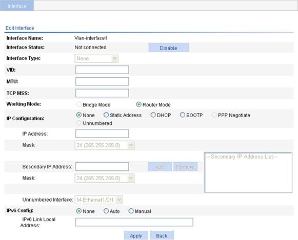
3. Modify the Layer 3 interface as described in Table 10.
4. Click Apply.
|
Item |
Description |
|
Interface Type |
Set the interface type, which can be Electrical port, Optical port, or None. |
|
Interface Status |
Display and set the interface status: · Connected—Indicates that the current status of the interface is up and connected. You can click the Disable button to shut down the interface. · Not connected—Indicates that the current status of the interface is up but not connected. You can click the Disable button to shut down the interface. · Administratively Down—Indicates that the interface is shut down by the administrator. You can click the Enable button to bring up the interface. After you click the Enable or Disable button, the page displaying interface information appears. For an interface whose status cannot be changed, the Enable or Disable button is not available. |
|
Working Mode |
Set the interface to operate in bridge mode or router mode. |
Interface management configuration example
Network requirements
As shown in Figure 24, create VLAN-interface 100, and specify its IP address as 10.1.1.2.
Configuration procedure
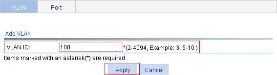
1. Create VLAN 100:
a. Select Network > VLAN from the navigation tree to enter the VLAN tab.
b. Click Add.
c. Enter 100 for VLAN ID.
d. Click Apply.
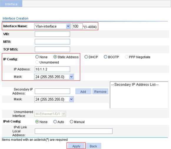
2. Create VLAN-interface 100, and assign an IP address to it:
a. Select Device > Interface from the navigation tree.
b. Click Add.
c. Select Vlan-interface from the Interface Name list, and then type the interface ID 100.
d. Select the Static Address option in the IP Config area.
e. Enter the IP address 10.1.1.2.
f. Select 24 (255.255.255.0) from the Mask list.
g. Click Apply.
Figure 25 Creating VLAN-interface 100
Overview
TR-069 is a DSL Forum technical specification for remote management of home network devices. It defines the general framework, message format, management method, and data model for managing and configuring home network devices.
TR-069 applies mainly to DSL access networks, which are hard to manage because end-user devices are dispersed and large in number. CWMP makes the management easier by using an autoconfiguration server to perform remote centralized management of customer premises equipment.
Figure 26 TR-069 network framework
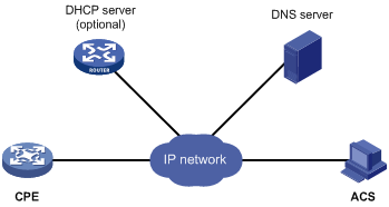
The basic CWMP network elements include:
· ACS—Autoconfiguration server, the management device in the network.
· CPE—Customer premises equipment, the managed device in the network.
· DNS server—TR-069 defines that an ACS and a CPE use URLs to identify and access each other. DNS is used to resolve the URLs.
· DHCP server—Assigns an IP address to an ACS and a CPE, and uses the options filed in the DHCP packet to issue configuration parameters to the CPE.
The H3C device is a CPE and uses TR-069 to communicate with an ACS.
For more information about TR-069, see Network Management and Monitoring Configuration Guide.
Feature and hardware compatibility
|
Hardware series |
model |
TR-069 compatibility |
|
WA4300 series |
WA4320-ACN WA4320H-ACN WA4320i-ACN WA4320-ACN-PI |
Yes |
|
WA4600 series |
WA4620i-ACN WA4620E-ACN |
No |
Configuration procedure
1. Select Device > TR-069 from the navigation tree to enter the TR-069 configuration page.
Figure 27 TR-069 configuration page
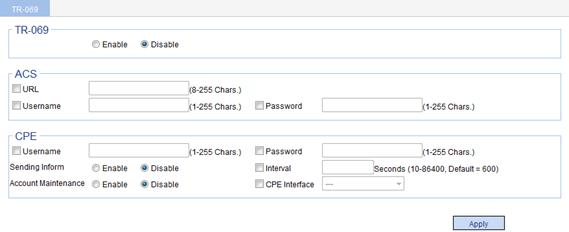
2. Set TR-069 parameters as described in Table 11.
3. Click Apply.
|
Item |
Description |
|
|
TR-069 |
Enable or disable TR-069. TR-069 configurations can take effect only after you enable TR-069. |
|
|
ACS |
URL. |
Configure the URL used by a CPE to initiate a connection to the ACS. |
|
Username. |
Configure the username used by a CPE to initiate a connection to the ACS. |
|
|
Password. |
Configure the password used by a CPE to initiate a connection to the ACS. You can specify a username without a password that is used in the authentication. If so, the configuration on the ACS and that on the CPE must be the same. |
|
|
CPE |
Username. |
Configure the username used by the CPE to authenticate the connection sent from the ACS. |
|
Password. |
Configure the password used by the CPE to authenticate the connection sent from the ACS. You can specify a username without a password that is used in the authentication. If so, the configuration on the ACS and that on the CPE must be the same. |
|
|
Sending Inform. |
Enable or disable CPE's periodical sending of Inform messages. |
|
|
Interval. |
Configure the interval between sending the Inform messages. |
|
|
Account Maintenance. |
Enable or disable the CPE to inform the ACS to change the password of the account TelecomAdmin. |
|
|
CPE Interface. |
Set the CPE connection interface. The CPE sends inform packets carrying the IP address of this interface to make the ACS establish a connection with the CPE using this IP address. |
|
Configuration guidelines
Follow these guidelines when you configure TR-069:
· Do not configure TR-069 on the Web to modify the TR-069 parameter settings if you have autoconfigured the CPE from the ACS. The autoconfigured settings from the ACS always take precedence over the settings on the Web.
· To remove the setting of a parameter, select the box in front of the parameter, clear its value, and click Apply.
The user management Web interface provides the following functions:
· Adding a local user, and specifying the password, access level, and service types for the user.
· Setting the super password for non-management level users to switch to the management level.
· Switching to the management level from a lower level.
Adding a local user
1. Select Device > Users from the navigation tree.
2. Click the Create tab.
The local user configuration page appears.
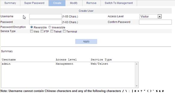
3. Configure the local user as described in Table 12.
4. Click Apply.
|
Item |
Description |
|
Username |
Enter a username for the user. |
|
Access Level |
Select an access level for the user. Users of different levels can perform different operations. User levels, in order from low to high, are as follows: · Visitor—Users of this level can perform only ping and traceroute operations. They can neither access the device data nor configure the device. · Monitor—Users of this level can perform ping and traceroute operations and access the device data, but they cannot configure the device. · Configure—Users of this level can perform ping and traceroute operations, access data on the device, and configure the device, but they cannot upgrade the host software, add/delete/modify users, or back up or restore the configuration file. · Management—Users of this level can perform any operations on the device. |
|
Password |
Set the password for the user. |
|
Confirm Password |
Enter the same password again. Otherwise, the system will prompt that the two passwords entered are not consistent when you apply the configuration. |
|
Password Encryption |
Set the encryption method for storing users' passwords: · Reversible—The device stores passwords by using reversible encryption. · Irreversible—The device stores passwords by using irreversible encryption. |
|
Service Type |
Select the service types for the user to use, including Web, FTP, Telnet, and terminal. You must select at least one service type. |
Setting the super password
A management level user can set the password for non-management level users to switch to the management level. If you do not configure the password, users cannot switch to the management level from a lower level.
To set the super password:
1. Select Device > Users from the navigation tree.
2. Click the Super Password tab.
Figure 29 Setting the super password
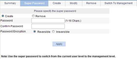
3. Set the super password as described in Table 13.
4. Click Apply.
|
Item |
Description |
|
Create/Remove |
Select the operation type: · Create—Configure or change the super password. · Remove—Remove the current super password. |
|
Password |
Set the password for non-management level users to switch to the management level. |
|
Confirm Password |
Enter the same password again. Otherwise, the system will prompt that the two passwords entered are not consistent when you apply the configuration. |
|
Password Encryption |
Set the encryption method for storing users' passwords: · Reversible—The device stores passwords by using reversible encryption. · Irreversible—The device stores passwords by using irreversible encryption. |
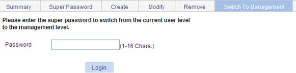
Switching to the management level
This function allows a user to switch from the current user level to the management level. To switch to the management level, a user must provide the correct super password.
The switchover operation does not change the access level configured for the user. The access level switchover of a user is only effective for the current login. When the user logs in to the Web interface again, the access level of the user is still the original level.
To switch to the management level:
1. Select Device > Users from the navigation tree.
2. Click the Switch To Management tab.
3. Enter the super password.
4. Click Login.
Figure 30 Switching to the management level
Overview
SNMP enables network administrators to read and set the variables on managed devices for state monitoring, troubleshooting, statistics collection, and other management purposes.
The SNMP framework comprises the following elements:
· SNMP manager—Works on an NMS to monitor and manage the SNMP-capable devices in the network.
· SNMP agent—Works on a managed device to receive and handle requests from the NMS, and send traps to the NMS when some events, such as interface state change, occur.
· Management Information Base (MIB)—Specifies the variables (for example, interface status and CPU usage) maintained by the SNMP agent for the SNMP manager to read and set.
An NMS and an SNMP agent must use the same SNMP version to communicate with each other.
H3C supports SNMPv1, SNMPv2c, and SNMPv3:
· SNMPv1—Uses community names for authentication. To access an SNMP agent, an NMS must use the same community name as set on the SNMP agent. If the community name used by the NMS is different from the community name set on the agent, the NMS cannot establish an SNMP session to access the agent or receive traps and notifications from the agent.
· SNMPv2c—Uses community names for authentication. SNMPv2c is compatible with SNMPv1, but supports more operation modes, data types, and error codes.
· SNMPv3—Uses a user-based security model (USM) to secure SNMP communication. You can configure authentication and privacy mechanisms to authenticate and encrypt SNMP packets for integrity, authenticity, and confidentiality.
For more information about SNMP, see Network Management and Monitoring Configuration Guide.
Configuring the SNMP agent
1. Select Device > SNMP from the navigation tree to enter the SNMP configuration page.
Figure 31 SNMP configuration page
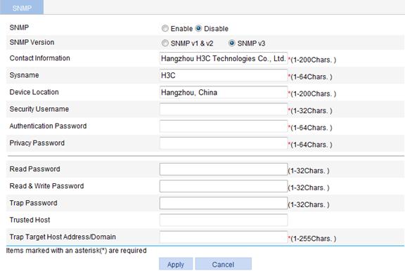
2. Configure SNMP settings as described in Table 14.
3. Click Apply.
|
Item |
Description |
|
SNMP |
Enable or disable the SNMP agent.
Disabling the SNMP agent can cause the removal of all SNMP-related settings. |
|
SNMP Version |
Set the SNMP version. Make sure the SNMP agent is using the same SNMP version as the NMS. On this page, v2 specifies SNMPv2c. |
|
Contact |
Configure contact information for system maintenance. |
|
Sysname |
Set the system name of the device. The configured system name appears at the top of the navigation tree. |
|
Device Location |
Configure the physical location of the device. |
|
Security Username |
Set a SNMP security username when the SNMP version is SNMPv3. This username must be the same as configured on the NMS. |
|
Authentication Password |
Set the authentication key when the SNMP version is SNMPv3. This authentication key must be the same as configured on the NMS. The authentication protocol is MD5 for the agent and NMS. |
|
Privacy Password |
Set the privacy key when the SNMP version is SNMPv3. This privacy password must be the same as configured on the NMS. The privacy protocol is DES56 for the agent and NMS. |
|
Read Password |
Set the read-only password when the SNMP version is SNMPv1 or SNMPv2c, with which the NMS can perform only read operation to the agent. The read password on the NMS and agent must be the same. |
|
Read & Write Password |
Set the read and write password when the SNMP version is SNMPv1 or SNMP v2c, with which the NMS can perform both read and write operations to the agent. The read and write password on the NMS and agent must be the same. |
|
Trap Password |
· Set the authentication password when the SNMP version is SNMPv1 or SNMP v2c, with which the agent can send traps to the NMS. The trap password must be the same as either the read password or the read & write password. The NMS and the agent must use the same password. · This item can be configured the trap password defaults to the security username and is not configurable when the SNMP version is SNMPv3. |
|
Trusted Host |
Set the trusted IP address of the agent. · If the trusted host is specified, only the NMS with the specified source IP address can access the agent. · If no trusted host is specified, there is no IP-address-based access control to the NMS. |
|
Trap Target Host Address/Domain |
Set the IP address or host name of the SNMP trap target host. |
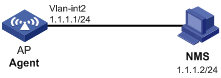
SNMPv1/v2c configuration example
Network requirements
As shown in Figure 32, the NMS (1.1.1.2/24) uses SNMPv1 or SNMPv2c to manage the AP (1.1.1.1/24), and the AP automatically sends traps to report events to the NMS.
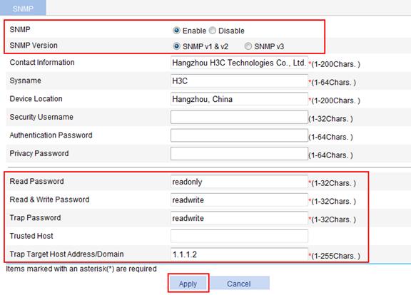
Configuring the AP (SNMP agent)
1. Select Device > SNMP from the navigation tree.
The SNMP configuration page appears, as shown in Figure 33.
2. Select Enable.
3. Select SNMPv1 & v2.
4. Enter readonly in the Read Password field.
5. Enter read&write in the Read & Write Password field.
6. Enter read&write in the Trap Password field.
7. Enter 1.1.1.2 in the Trap Target Host field.
8. Click Apply.
Figure 33 Configuring the SNMP agent
Configuring the NMS
The SNMP settings on the agent and the NMS must match.
1. Specify the SNMPv1 or SNMPv2c version.
2. Set the read-only community name to readonly, and the read and write community name to readwrite.
For the configuration procedure on the NMS, see the NMS user manual.
Verifying the configuration
· Verify that the NMS can access and set some MIB variables on the AP.
· Shut down and bring up an idle interface on the AP, and verify that the NMS can receive the link traps from the AP.
SNMPv3 configuration example
Network requirements
As shown in Figure 34, the NMS (1.1.1.2/24) uses SNMPv3 to monitor and manage the AP (1.1.1.1/24), and the AP automatically sends traps to report events to the NMS.
The NMS and the AP perform authentication when they set up an SNMP session, and the authentication key is authkey. The NMS and agent also encrypt the SNMP packets between them, and the privacy key prikey.

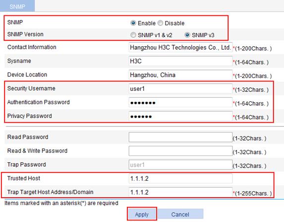
Configuring the SNMP agent
1. Select Device > SNMP from the navigation tree, as shown in Figure 35.
The SNMP configuration page appears, as shown Figure 35.
2. Select Enable.
3. Select SNMPv3.
4. Enter user1 in the Security Username field.
5. Enter authkey in the Authentication Password field.
6. Enter prikey in the Privacy Password field.
7. Enter 1.1.1.2 in the Trusted Host field.
8. Enter 1.1.1.2 in the Trap Target Host field.
9. Click Apply.
Figure 35 Configuring the SNMP agent
Configuring the SNMP NMS
The SNMP settings on the agent and the NMS must match.
1. Specify the SNMPv3 version.
2. Set the username to user1, authentication algorithm to MD5, authentication key to authkey, encryption algorithm to DES56, and privacy key to prikey.
For information about configuring the NMS, see the NMS user manual.
Verifying the configuration
· Verify that the NMS can access and set some MIB variables on the AP.
· Shut down and bring up an idle interface on the AP, and verify that the NMS can receive the link traps from the agent.
You can perform the Ethernet port loopback test to check whether an Ethernet port works normally. During the test, the port cannot forward data packets normally.
Ethernet port loopback test can be one of the following types:
· Internal loopback test—A self loop is established in the switching chip to check whether there is a chip failure related to the functions of the port.
· External loopback test—A self-loop header is used on the port. Packets forwarded by the port will be received by itself through the self-loop header. You can use the external loopback test to check whether there is a hardware failure on the port.
Configuration procedure
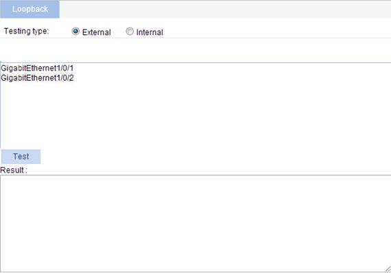
1. Select Device > Loopback from the navigation tree to enter the loopback test configuration page.
Figure 36 Loopback test configuration page
|
|
NOTE: Support for the interface information displayed on the page varies by device model. |
2. Configure parameters for the loopback test, as described in Table 15.
|
Item |
Description |
|
Testing type |
Set the loopback test type, which can be selected between External and Internal. |
After you select a testing type, you must select an interface on which you want to perform the loopback test from the interface list on the lower part of the page.
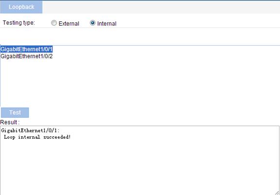
3. Click Test to start the loopback test.
4. After the test is complete, the test result appears in the Result box.
Figure 37 Loopback test result (for internal loopback test)
|
|
NOTE: Support for the interface information displayed on the page varies by device model. |
Configuration guidelines
Follow these guidelines when you perform a loopback test:
· You can perform an internal loopback test, but not an external loopback test on a port that is physically down. However, you cannot perform either test on a port that is manually shut down.
· The system does not allow Rate, Duplex, Cable Type and Port Status configuration on a port under a loopback test.
· An Ethernet port operates in full duplex mode when the loopback test is performed. It restores its original duplex mode after the loopback test.