- Table of Contents
- Related Documents
-
| Title | Size | Download |
|---|---|---|
| 11-Advanced Settings | 613.34 KB |
Configuring WLAN advanced settings
Switching the AP to operate in fit AP mode
Configuring continuous transmitting mode
Configuring uplink interface monitoring·
Configuring a channel busy test
Configuring multicast optimization
Band navigation configuration example
Multicast optimization configuration example
Advanced settings overview
District code
Radio frequencies for countries and regions vary based on country regulations. A district code determines characteristics such as frequency range, channel, and transmit power level. Configure the valid country code or area code for a WLAN device to meet the specific country regulations.
Switching to fit AP mode
An AP that supports the fat and fit AP modes can switch from fat to fit to cooperate with an AC or unified switch. You can scale a small-sized network with fat APs smoothly by switching their operating mode to the fit AP mode. Centralized management is achieved.
Continuous transmitting mode
The continuous transmitting mode is used for test only. Do not use the function unless necessary.
Uplink interface monitoring
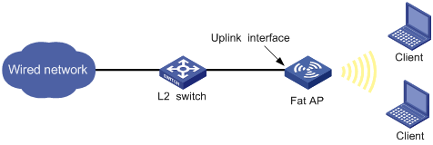
A fat AP connects to an uplink network through the Ethernet interface, as shown in Figure 1. With uplink interface monitoring enabled, the AP can detect uplink interface faults. When such a fault occurs, the SSID of the AP is not available for the clients to access the WLAN service until it recovers. Then the clients turn to search for SSID of another functional AP. For more information about how to configure uplink interface monitoring, see "Configuring uplink interface monitoring."
Figure 1 Network diagram for uplink interface monitoring
Channel busy test
The channel busy test is a tool to test how busy a channel is. It tests channels supported by the district code one by one, and provides a busy rate for each channel. This avoids the situation that some channels are heavily loaded and some are idle.
During a channel busy test, the AP does not provide any WLAN services. All the connected clients are disconnected and WLAN packets are discarded.
Band navigation
The 2.4 GHz band is often congested. Band navigation enables APs to accept dual-band (2.4 GHz and 5 GHz) clients on their 5 GHz radio, increasing overall network performance.
When band navigation is enabled, the AP directs clients to its 2.4 GHz or 5 GHz radio by following these principles:
· For a 2.4 GHz client, the AP associates to the client after rejecting it several times.
· For a dual-band client, the AP directs the client to its 5 GHz radio.
· For a 5 GHz- client, the AP associates to the client on its 5 GHz radio.
The AP checks the RSSI of a dual-band client before directing the client to the 5 GHz radio. If the RSSI is lower than the value, the AP does not direct the client to the 5 GHz band.
If the number of clients on the 5 GHz radio reaches the upper limit, and the gap between the number of clients on the 5 GHz radio and that on the 2.4 GHz radio reaches the upper limit, the AP denies the client’s association to the 5 GHz radio, and allows new clients to associate to the 2.4 GHz radio. If a client has been denied more than the maximum times on the 5 GHz radio, the AP considers that the client is unable to associate to any other AP, and allows the 5 GHz radio to accept the client.
Multicast optimization
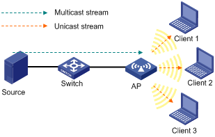
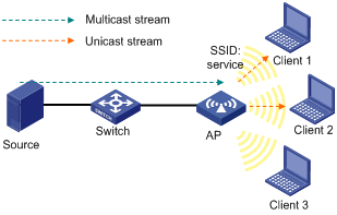
WLAN selects the lowest transmit rate for multicast packets and provides no multicast retransmission mechanism. Therefore, WLAN cannot meet the requirements of some multicast applications that are not delay-sensitive but are data-integrity sensitive, such as HD VoD. The multicast optimization feature can solve these problems by enabling APs to convert multicast packets to unicast packets, so WLAN can provide retransmission service and higher transmit rates for the converted unicast packets.
Unless otherwise specified, the unicast packets in this chapter refer to the wireless unicast packets that have the priority of video.
Figure 2 Multicast data transmission when multicast optimization is enabled
With multicast optimization enabled, the AP listens to the IGMP reports and leave messages sent by clients. When the AP receives an IGMP report, it adds or updates a multicast optimization entry and updates the multicast source addresses allowed by the client (for IGMPv3 and MLDv2 packets). When the AP receives an IGMP leave message or when a multicast optimization entry ages out, the AP removes the entry. When multicast optimization is disabled, all multicast optimization entries are removed.
After creating multicast entries, the AP listens to non-IGMP and non-MLD multicast packets sent from the multicast source to clients, and matches the multicast address of the packets to the multicast optimization entries. If a match is found, the AP converts the multicast packets to unicast packets and sends the unicast packets to all the clients in the multicast entries. If no match is found, the AP directly sends the multicast packets.
To avoid performance degradation, you can configure the maximum number of clients that multicast optimization can support. When the maximum number is reached, the AP takes either of the following actions, depending on which one is configured:
· Halt—A new client can join a multicast group and receive multicast packets, and a multicast optimization entry can be created for the client. However, the multicast optimization function for all clients in the multicast group becomes invalid. When the number of clients drops below the upper limit, the multicast optimization function takes effect again.
· Reject-client—A new client can join a multicast group, but no new multicast optimization entries can be created. If multicast optimization entries have been created for other clients in the multicast group, the client cannot receive multicast packets. Otherwise, the client can receive multicast packets.
|
|
NOTE: If you configure Halt first, and then configure Reject-client, the existing multicast optimization entries still take effect. |
Configuring WLAN advanced settings
Setting a district code
1. Select Advanced > District Code from the navigation tree.
The page for setting a district code appears.
Figure 3 Setting a district code

2. Set a district code as described in Table 1.
3. Click Apply.
|
Item |
Description |
|
District Code |
Select a district code. Configure the valid district code for a WLAN device to meet the country regulations. |
If the list is grayed out, the setting is preconfigured to meet the country regulation of the target market and is locked. It cannot be changed.
Switching the AP to operate in fit AP mode
Before switching the operating mode, make sure the application file of the fit AP has been loaded to the AC or the wireless switch. Otherwise, the AP cannot operate properly after its operating mode is switched.
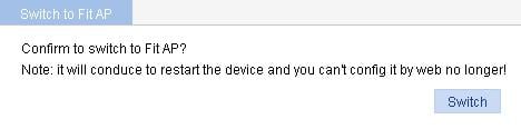
1. Select Advanced > Switch to Fit AP from the navigation tree.
The page for switching the fit AP mode appears.
2. Click Switch to switch the operating mode from fat AP to fit AP.
Figure 4 Switching to fit AP mode
Configuring continuous transmitting mode
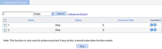
1. Select Advanced > Continuous Transmit from the navigation tree.
The continuous transmitting mode configuration page appears.
Figure 5 Continuous transmitting mode configuration page
2.
Click the ![]() icon for the target radio to enter the page for configuring transmission rate.
icon for the target radio to enter the page for configuring transmission rate.
The transmission rate varies with radio mode.
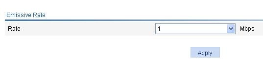
¡ When the radio mode is 802.11a/b/g, the page as shown in Figure 6 appears. Select a transmission rate from the list.
Figure 6 Selecting an transmission rate (802.11a/b/g)
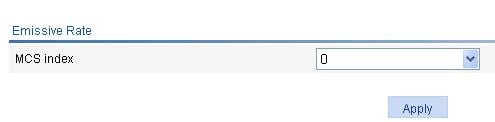
¡ When the radio mode is 802.11n, the page as shown in Figure 7 appears. Select an MCS index value to specify the 802.11n transmission rate. For more information about MCS, see "Configuring radios."
Figure 7 Selecting an MCS index (802.11n)
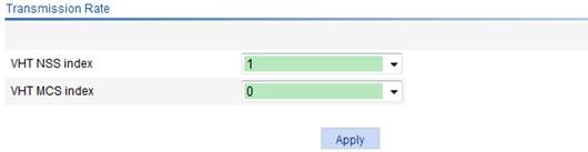
¡ When the radio mode is 802.11ac, the page as shown in Figure 8 appears. Select a VHT MCS index value and an NSS to specify the 802.11ac transmission rate. For more information about VHT MCS and NSS, see "Configuring radios."
Figure 8 Selecting a VHT MCS index and an NSS
3. Click Apply.
4. To stop the continuous transmitting mode, use either of the methods:
¡ Click the ![]() icon for the target radio.
icon for the target radio.
¡ Or, select the target radio, and click Stop.
After the continuous transmit is stopped, the transmission rate value on the page as shown in Figure 5 displays as 0.
Configuring uplink interface monitoring
1. Select Advanced > Uplink Monitor from the navigation tree.
The uplink interface monitoring configuration page appears.
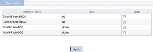
Figure 9 Uplink interface monitoring configuration page
|
|
NOTE: The interface information displayed on the page varies by device model. |
2. Configure uplink interface monitoring as described in Table 2.
3. Click Apply.
|
Item |
Description |
|
Interface Name |
Interfaces that can be configured as uplink interfaces. |
|
Status |
· up—The interface is up. · down—The interface is down. The uplink interface state is the state of the link of the WDS that is bound to the radio interface. |
|
Uplink |
Select the check box to configure the interface as an uplink interface. |
Configuring a channel busy test
1. Select Advanced > Channel Busy Test from the navigation tree.
The channel busy test configuration page appears.
Figure 10 Channel busy test configuration page
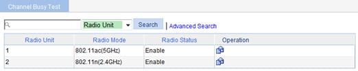
2.
Click the ![]() icon for the target
AP to enter channel busy testing page.
icon for the target
AP to enter channel busy testing page.
Figure 11 Testing busy rate of channels
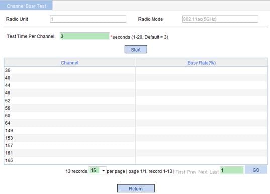
3. Configure channel busy test as described in Table 3.
4. Click Start to start the testing.
|
Item |
Description |
|
Radio Unit |
Radio unit of the AP. |
|
Radio Mode |
Radio mode of the AP. |
|
Test time per channel |
Set a time period in seconds within which a channel is tested. The default value is 3 seconds. Before the channel busy test completes, do not start another test for the same channel. |
Configuring band navigation
When band navigation is enabled, the client association efficiency is affected, so this feature is not recommended in a scenario where most clients use 2.4 GHz.
Band navigation is not recommended in a delay-sensitive network.
Configuration prerequisites
For band navigation to operate correctly, verify the following information:
· The fast association function is disabled. By default, the fast association function is disabled. For more information about fast association, see "Configuring access services."
· Band navigation is enabled for the AP. By default, band navigation is enabled for the AP.
· The SSID is bound to the 2.4 GHz and 5 GHz radios of the AP.
Configuring band navigation
1. Select Advance > Band Navigation from the navigation tree.
Figure 12 Configuring band navigation
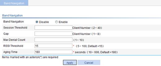
2. Configure band navigation as described in Table 4.
3. Click OK.
|
Item |
Description |
|
Band Navigation |
· Enable—Enable band navigation. · Disable—Disable band navigation. By default, band navigation is disabled globally. |
|
Session Threshold |
Session threshold for clients on the 5 GHz band. |
|
Gap |
Session gap, which is the number of clients on the 5 GHz band minus the number of clients on the 2.4 GHz band. If the number of clients on the 5 GHz radio has reached the upper limit, and the gap between the number of clients on the 5 GHz radio and that on the 2.4 GHz radio has reached the upper limit, the AP denies the client’s association to the 5 GHz radio, and allows new clients to associate to the 2.4 GHz radio. |
|
Max Denial Count |
Maximum denial count of client association requests. If a client has been denied more than the maximum times on the 5 GHz radio, the AP considers that the client is unable to associate to any other AP, and allows the 5 GHz radio to accept the client. |
|
RSSI Threshold |
Band navigation RSSI threshold. The AP checks the RSSI of a dual-band client before directing the client to the 5 GHz radio. If the RSSI is lower than the value, the AP does not direct the client to the 5 GHz band. |
|
Aging Time |
Client information aging time. The AP records the client information when a client tries to associate to it. If the AP receives the probe request or association request sent by the client before the aging time expires, the AP refreshes the client information and restarts the aging timer. If not, the AP removes the client information, and does not count the client during band navigation. |
Configuring multicast optimization
Enabling multicast optimization
1. Select Advanced > Multicast Optimization from the navigation tree.
Figure 13 Configuring multicast optimization
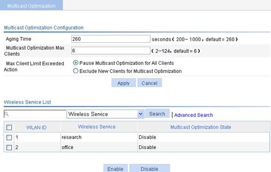
2. Configure multicast optimization as described in Table 5.
3. Click Apply.
|
Item |
Description |
|
Aging Time |
Specify the aging time for multicast optimization entries. If the AP does not receive an IGMP report from a client within the aging time, the AP removes the multicast optimization entry for the client. |
|
Multicast Optimization Max Clients |
Specify the maximum number of clients supported by multicast optimization. A client can join up to eight multicast groups. If a client joins multiple multicast groups, the client is counted as multiple clients in multicast optimization statistics. For example, if a client has joined two multicast groups, the client is counted as two clients in the multicast optimization statistics. |
|
Max Client Limit Exceeded Action |
· Pause Multicast Optimization for All Clients—Invalidate the multicast optimization function. A new client can join a multicast group and receive multicast packets, and a multicast optimization entry can be created for the client. However, the multicast optimization function for all clients in the multicast group becomes invalid. When the number of clients drops below the upper limit, the multicast optimization function takes effect again. · Exclude New Clients for Multicast Optimization—Reject new clients. A new client can join a multicast group, but no new multicast optimization entries can be created. If multicast optimization entries have been created for other clients in the multicast group, the client cannot receive multicast packets. Otherwise, the client can receive multicast packets. By default, the multicast optimization function becomes invalid when the maximum number of clients supported by multicast optimization is reached. If you configure Pause Multicast Optimization for All Clients first, and then configure Exclude New Clients for Multicast Optimization, the existing multicast optimization entries still take effect. |
4. Select the target wireless service.
5. Click Enable.
Displaying multicast optimization information
1. Select Advanced > Multicast Optimization from the navigation tree.
2. Click the target radio.
Figure 14 Displaying multicast optimization information
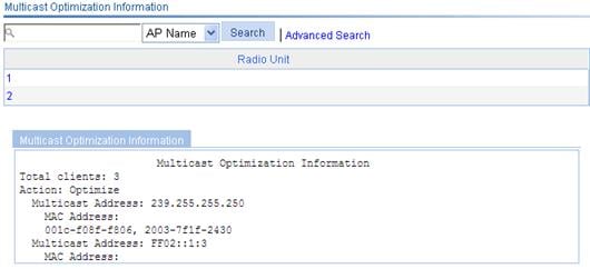
Table 6 Configuration items
|
Item |
Description |
|
Total clients |
Total number of clients involved in multicast optimization. If a client joins multiple multicast groups, the client is counted as multiple clients. For example, if a client has joined two multicast groups through a radio, the client is counted as two clients by multicast optimization. |
|
Action |
Operating status of the multicast optimization function: · Optimize—The multicast optimization function is operating. · Halt—The multicast optimization function has been halted. |
|
Multicast Address |
Address of the multicast group that the clients have joined. |
|
MAC Address |
MAC addresses of the clients that have joined the multicast group. |
Band navigation configuration example
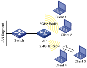
Network requirements
As shown in Figure 15, Client 1 through Client 4 try to associate to AP 1, and the two radios of AP 1 operate at 5 GHz and 2.4 GHz. Client 1, Client 2, and Client 3 are dual-band clients, and Client 4 is a single-band (2.4 GHz) client. Configure band navigation to direct clients to different radios of the AP.
Configuring the AP
To enable band navigation to operate properly, make sure of the following:
· The fast association function is disabled. By default, the fast association function is disabled.
· Band navigation is enabled for the AP. By default, band navigation is enabled for the AP.
1. Configure wireless service:
a. Select Wireless Service > Access Service from the navigation tree.
b. Click Add.
c. On the page that appears, set the service name to band-navigation, select the wireless service type Clear, and click Apply.
2. Enable wireless service:
a. Select Wireless Service > Access Service from the navigation tree.
b. Set the band-navigation box.
c. Click Enable.
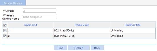
3. Bind an AP radio to the wireless service:
a. Select Wireless Service > Access Service from the navigation tree.
b. Click the ![]() icon for the wireless service band-navigation
to enter the page for binding an AP radio.
icon for the wireless service band-navigation
to enter the page for binding an AP radio.
c. Select the boxes before 802.11ac(GHz) and 802.11n(2.4GHz).
d. Click Bind.
4. Enable 802.11ac(GHz) and 802.11n(2.4GHz) radios:
(Optional) By default, 802.11ac(GHz) and 802.11n(2.4GHz) radios are enabled.
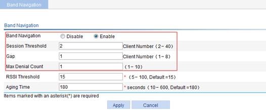
5. Configure band navigation:
a. Select Advance > Band Navigation from the navigation tree.
b. On the page that appears, click Enable, and type the Session Threshold 2, Gap 1, and Max Denial Count 1. Use the default values for other options.
c. Click Apply.
Figure 17 Configuring band navigation
Verifying the configuration
Client 1 and Client 2 are associated to the 5 GHz radio of the AP, and Client 4 can only be associated to the 2.4 GHz radio of the AP. Because the number of clients on the 5 GHz radio has reached the upper limit 2, and the gap between the number of clients on the 5 GHz radio and 2.4 GHz radio has reached the session gap 1, Client 3 will be associated to the 2.4 GHz radio of the AP.
Multicast optimization configuration example
Network requirements
As shown in Figure 18, enable multicast optimization for the AP to convert multicast packets to unicast packets for up to two clients.
Configuring the AP
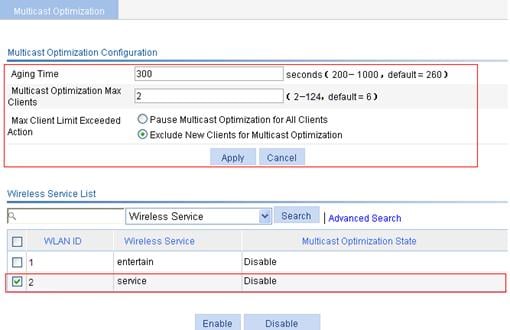
1. Select Advanced > Multicast Optimization from the navigation tree.
2. Set the Aging Time to 300 seconds, the Multicast Optimization Max Clients to 2, and Max Client Limit Exceeded Action to Exclude New Clients for Multicast Optimization.
3. Click Apply.
4. Select the target wireless service.
5. Click Enable.
Figure 19 Configuring multicast optimization
Verifying the configuration
Client 1 and Client 2 are associated with a radio of the AP. Because the number of clients on the radio has reached the upper limit 2, Client 3 cannot be added to multicast optimization entries.