- Table of Contents
- Related Documents
-
| Title | Size | Download |
|---|---|---|
| 06-Wireless Service Configuration | 2.99 MB |
Recommended configuration procedure
Configuring clear type wireless service
Configuring crypto type wireless service
Security parameter dependencies
Binding an AP radio to a wireless service
Configuring a neighbor MAC address
Configuring advanced WDS settings
Configuring the repeater service
Wireless access configuration examples
Wireless service configuration example
Access service-based VLAN configuration example
WPA-PSK authentication configuration example
Local MAC authentication configuration example
Remote MAC authentication configuration example
Remote 802.1X authentication configuration example
Dynamic WEP encryption-802.1X authentication configuration example
Wireless service overview
Wireless Local Area Networks (WLANs) have become very popular because they are very easy to set up and use, and have relatively low costs. Generally, one or more access points (APs) can cover a building or an area.
· WLAN client connectivity to conventional 802.3 LANs
· Secured WLAN access with different authentication and encryption methods
· Seamless roaming of WLAN clients in the mobility domain
Access service
Terminology
· Client—A handheld computer or laptop with a wireless NIC or a terminal that supports WiFi can be a WLAN client.
· Fat AP—A fat AP controls and manages all associated wireless stations and bridges frames between wired and wireless networks.
· SSID—The service set identifier. A client scans all networks at first, and then selects an SSID to connect to a wireless network.
· Wireless medium—A medium that is used for transmitting frames between wireless clients. Radio frequency is used as the wireless medium in the WLAN system.
Wireless client access
A wireless client access process involves three steps: active/passive scanning surrounding wireless services, authentication, and association, as shown in Figure 1.
Figure 1 Establishing a client access
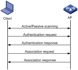
Scanning
A wireless client can get the surrounding wireless network information in two ways, passive scanning or active scanning. With passive scanning, a wireless client gets wireless network information through listening to Beacon frames sent by surrounding APs. With active scanning, a wireless actively sends a probe request frame during scanning, and gets network signals by received probe response frames.
When a wireless client operates, it usually uses both passive scanning and active scanning to get information about surrounding wireless networks.
1. Active scanning
When a wireless client operates, it periodically searches for (that is, scans) surrounding wireless networks. Active scanning falls into two modes according to whether a specified SSID is carried in a probe request.
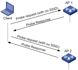
¡ A client sends a probe request (with the SSID null, that is, the SSID IE length is 0): The client periodically sends a probe request frame on each of its supported channels to scan wireless networks. APs that receive the probe request send a probe response, which carries the available wireless network information. The client associates with the AP with the strongest signal. This active scanning mode enables a client to actively get acquainted with the available wireless services and select to access the proper wireless network as needed. The active scanning process of a wireless client is as shown in Figure 2.
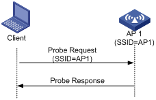
A client sends a probe request (with a specified SSID): When the wireless client is configured to access a specific wireless network or has already successfully accessed a wireless network, the client periodically sends a probe request carrying the specified SSID of the configured or connected wireless network. When an AP that can provide the wireless service with the specified SSID receives the probe request, it sends a probe response. This active scanning mode enables a client to access a specified wireless network. The active scanning process is as shown in Figure 3.
Figure 3 Active scanning (the probe request carries the specified SSID AP 1)
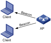
2. Passive scanning
Passive scanning is used by clients to discover surrounding wireless networks through listening to the beacon frames periodically sent by an AP. All APs providing wireless services periodically send beacons frames, so that wireless clients can periodically listen to beacon frames on the supported channels to get information about surrounding wireless networks. Passive scanning is used by a client when it wants to save battery power. Typically, VoIP clients adopt the passive scanning mode. The passive scanning process is as shown in Figure 4.
Authentication
To secure wireless links, the wireless clients must be authenticated before accessing the AP, and only wireless clients passing the authentication can be associated with the AP. 802.11 links define two authentication mechanisms: open system authentication and shared key authentication.
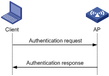
· Open system authentication
Open system authentication is the default authentication algorithm. This is the simplest of the available authentication algorithms. Essentially it is a null authentication algorithm. Any client that requests authentication with this algorithm can become authenticated. Open system authentication is not required to be successful as an AP may decline to authenticate the client. Open system authentication involves a two-step authentication process. In the first step, the wireless client sends a request for authentication. In the second step, the AP returns the result to the client.
Figure 5 Open system authentication process
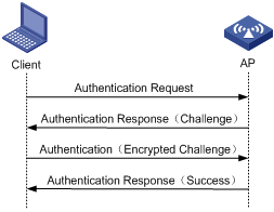
· Shared key authentication
Figure 6 shows a shared key authentication process. The two parties have the same shared key configured.
a. The client sends an authentication request to the AP.
b. The AP randomly generates a challenge and sends it to the client.
c. The client uses the shared key to encrypt the challenge and sends it to the AP.
d. The AP uses the shared key to encrypt the challenge and compares the result with that received from the client. If they are identical, the client passes the link authentication. If not, the link authentication fails.
Figure 6 Shared key authentication process
Association
A client that wants to access a wireless network via an AP must be associated with that AP. Once the client chooses a compatible network with a specified SSID and passes the link authentication to an AP, it sends an association request frame to the AP. The AP detects the capability information carried in the association request frame, determines the capability supported by the wireless client, and sends an association response to the client to notify the client of the association result. Usually, a client can associate with only one AP at a time, and an association process is always initiated by the client.
WLAN data security
Compared with wired networks, WLAN networks are more susceptible to attacks because all WLAN devices share the same medium. Therefore, every device can receive data from any other sending device. If no security service is provided, plain-text data is transmitted over the WLAN.
To secure data transmission, 802.11 protocols provide some encryption methods to ensure that devices without the right key cannot read encrypted data.
1. WEP encryption
Wired Equivalent Privacy (WEP) was developed to protect data exchanged among authorized users in a wireless LAN from casual eavesdropping. WEP uses RC4 encryption for confidentiality. WEP encryption falls into static and dynamic encryption according to how a WEP key is generated.
· Static WEP encryption
With Static WEP encryption, all clients using the same SSID must use the same encryption key. If the encryption key is deciphered or lost, attackers will get all encrypted data. In addition, periodical manual key update brings great management workload.
· Dynamic WEP encryption
Dynamic WEP encryption is a great improvement over static WEP encryption. With dynamic WEP encryption, WEP keys are negotiated between client and server through the 802.1X protocol so that each client is assigned a different WEP key, which can be updated periodically to further improve unicast frame transmission security.
Although WEP encryption increases the difficulty of network interception and session hijacking, it still has weaknesses due to limitations of RC4 encryption algorithm and static key configuration.
2. TKIP encryption
Temporal key integrity Protocol (TKIP) and WEP both use the RC4 algorithm, but TKIP has many advantages over WEP, and provides more secure protection for WLAN as follows:
¡ TKIP provides longer IVs to improve encryption security. Compared with WEP encryption, TKIP encryption uses 128–bit RC4 encryption algorithm, and increases the length of IVs from 24 bits to 48 bits.
¡ TKIP allows for dynamic key negotiation to avoid static key configuration. TKIP replaces a single static key with a base key generated by an authentication server. TKIP dynamic keys cannot be easily deciphered.
¡ TKIP offers MIC and countermeasures. If a packet fails the MIC, the data may be tampered, and the system may be attacked. If two packets fail the MIC in a certain period, the AP automatically takes countermeasures. It will not provide services in a certain period to prevent attacks.
3. AES-CCMP encryption
CTR with CBC-MAC protocol (CCMP) is based on the CCM of the AES encryption algorithm. CCM combines CTR for confidentiality and CBC-MAC for authentication and integrity. CCM protects the integrity of both the MPDU Data field and selected portions of the IEEE 802.11 MPDU header. The AES block algorithm in CCMP uses a 128-bit key and a 128-bit block size. Similarly, CCMP contains a dynamic key negotiation and management method, so that each wireless client can dynamically negotiate a key suite, which can be updated periodically to further improve the security of the CCMP encryption mechanism. During the encryption process, CCMP uses a 48-bit packet number (PN) to make sure each encrypted packet uses a different PN, improving the security to a certain extent.
Client access authentication
When a wireless client sets up a wireless link with an AP, the wireless client is considered to have accessed the wireless network. However, for the security and management of the wireless network, the wireless client can actually access the network resources after passing the subsequent access authentication. Among the authentication mechanisms, pre-shared key (PSK) and 802.1X authentication accompany the dynamic key negotiation and management of the wireless link, and therefore, they are closely related to wireless link negotiation. However, they are not directly related to the wireless link.
1. PSK authentication
Both WPA wireless access and WPA2 wireless access support PSK authentication. To implement PSK authentication, the client and the authenticator must have the same shared key configured.
Four-way handshake key negotiation exchanges four key packets of 802.1X to negotiate the private keys of the wireless link at the wireless client side and the AP side, and the pre-shared key is used as the seed key for key negotiation. During the negotiation process, the seed key is used by two parties for verification. The key negotiation succeeds only when the key setting is the same, that is, the wireless client successfully passes the PSK access authentication. Otherwise, the wireless client fails to pass the PSK access authentication, and the link of the wireless client will be broken.
2. 802.1X authentication
As a port-based access control protocol, 802.1X authenticates and controls accessing devices at the port level. A device connected to an 802.1X-enabled port of a WLAN access control device can access the resources on the WLAN only after passing authentication.
3. MAC authentication
MAC authentication provides a way for authenticating users based on ports and MAC addresses. For this authentication, the user does not need to install any client software. When the device first detects the MAC address of a user, it starts the authentication for the user. During the authentication process, the user does not need to manually enter username or password. In WLAN applications, MAC authentication needs to get the MAC addresses of the clients to access the wireless network in advance. Therefore, MAC authentication is applicable to small-scaled networks with relatively fixed users, for example, SOHO and small offices.
MAC authentication falls into two modes:
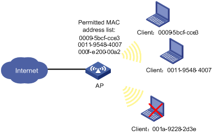
¡ Local MAC authentication—When this authentication mode is adopted, configure local usernames and passwords on the device, and the authentication is directly performed on the device. Usually, you can use the MAC address as the username, and you need to know the MAC addresses of wireless access clients in advance and configure the MAC addresses as usernames. When clients access the wireless network, only the clients whose MAC addresses exist on the device can pass the authentication.
Figure 7 Local MAC authentication
¡ Remote MAC authentication—RADIUS based MAC authentication. When RADIUS-based MAC authentication is used, the device operates as the RADIUS client, and cooperates with the RADIUS server to perform the MAC authentication. If the current client is found as an unknown client, the AP operates as the RADIUS client, and cooperates with the RADIUS server to perform the MAC authentication for the client. After the RADIUS server finishes the authentication for the client, the client can access the wireless network, and the RADIUS server can issue the corresponding authorization information.
Figure 8 Remote MAC authentication
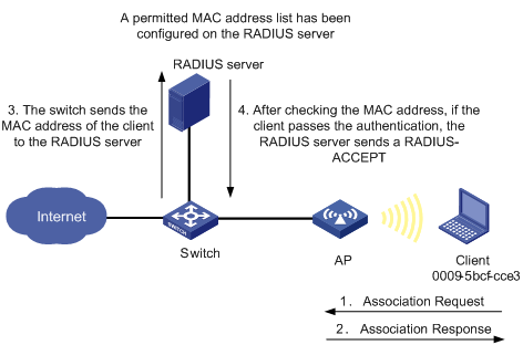
When a RADIUS server is used for MAC authentication, you can specify a domain for each wireless service, and send MAC authentication information of different SSIDs to different remote RADIUS servers.
Introduction to WDS
Wireless distribution system (WDS) wireless bridging uses wireless links to connect two or more separate wired LANs or WLANs to provide connectivity between them.
Advantages of WDS
802.11 based WLAN technologies are widely applied in the home, SOHO, and enterprise scenarios, allowing users to easily access the Internet. To provide network access services for wireless users, APs have to be connected to existing wired networks. In the traditional method, APs must be connected to wired networks. As a result, the network deployment cost is high, and it requires a lot time to deploy a large-scaled network.
WDS enables you to deploy a WLAN easily in some complex environments. It has the following advantages:
· Wireless connectivity between two separate LAN segments.
· Low cost for high performance deployment options.
· Expandability without the need for new wiring or more access points.
· Easy to deploy in scenarios of company, office, large warehouses, manufacturing, ports and waterfronts, and so on.
WDS network topologies
The WDS feature provides the following three topologies as required by actual applications. WDS is implemented through configuration of a peer MAC address for each AP. For more information, see "Configuring a neighbor MAC address."
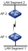
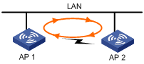
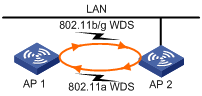
Point to point bridge connection
In this network, WDS uses two devices to form a bridge between two LANs, and interconnect the two LANs. In actual applications, each device can determine the bridge connection to be set up by configuring the MAC address of the peer device. As shown in Figure 9, a WDS bridge link is set up between AP 1 and AP 2 to connect LAN segment 1 and LAN segment 2 to form a unified LAN. When users in LAN segment 1 are to access resources of LAN segment 2, all packets will be transformed into wireless packets by AP 1 and sent to AP 2 through the wireless bridge link, restored on AP 2, and then sent to the destination, and vice versa.
Figure 9 WDS point to point bridge connection
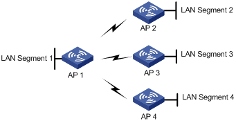
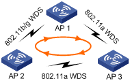
Point to multi-point bridge connection
In this topology, a device acts as the centralized device, and all the other devices set up wireless bridge connections with only the centralized device, interconnecting multiple networks. This topology conveniently connects multiple network islands to existing networks. However, all data exchanged between each two branch networks is forwarded by the centralized device.
Figure 10 WDS point to multi-point bridge connection
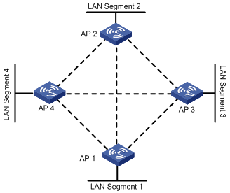
Mesh bridge connection
In this topology, multiple bridging devices can form mesh wireless bridge connections and interconnect multiple LANs through manual configuration or self detection. In a mesh bridge network, when a WDS link fails, backup links can take over. However, you must use STP to eliminate loops in actual applications.
Figure 11 Self topology detection and bridging
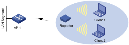
Introduction to repeater mode
An AP acting as a repeater can set up a link with another AP through a WDS link and provide wireless access service for clients at the same time. An AP acting as a repeater can not only create wireless networks but also use WDS bridge connections to connect wireless networks to the existing network. As shown in Figure 12, the repeater does not directly connect to the wired LAN. However, the repeater can provide wired LAN access service for Client 1 and Client 2. For applications, an AP in repeater mode deployed in the network increases the wireless communication distance and WLAN coverage.
The interface types and output information vary by device model and radio type.
Configuring access service
Recommended configuration procedure
|
Step |
Remarks |
|
Required. |
|
|
2. Configuring wireless service: |
Required. Use either approach. Complete the security settings as needed. |
|
Required. |
|
|
Required. |
|
|
Optional. |
Creating a wireless service
1. Select Wireless Service > Access Service from the navigation tree.
The page for configuring an access service appears.
Figure 13 Configuring access service

2. Click Add.
The page for creating a wireless service appears.
Figure 14 Creating a wireless service

3. Configure the wireless service as described in Table 1.
4. Click Apply.
|
Item |
Description |
|
Wireless Service Name |
Set the SSID. An SSID must be as unique as possible. For security, the company name cannot be contained in the SSID. Meanwhile, do not use a long random string as the SSID, because it only adds the Beacon frame length and usage complexity, without any improvement to wireless security. |
|
Wireless Service Type |
Select the wireless service type: · clear—The SSID is not encrypted. · crypto—The SSID is encrypted. |
Configuring clear type wireless service
Configuring basic settings for a clear type wireless service
1. Select Wireless Service > Access Service from the navigation tree.
2.
Click the ![]() icon for the target clear type wireless service.
icon for the target clear type wireless service.
The page for configuring a wireless service appears.
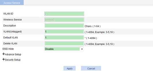
Figure 15 Configuring clear type wireless service
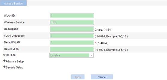
3. Configure the basic settings for the clear type wireless service as described in Table 2.
4. Click Apply.
|
Item |
Description |
|
Wireless service ID |
ID of the wireless service. |
|
Wireless Service |
Display the selected SSID. |
|
VLAN (Untagged) |
Enter the ID of the VLAN whose packets are to be sent untagged. VLAN (Untagged) indicates that the port sends the traffic of the VLAN with the VLAN tag removed. |
|
Default VLAN |
Set the default VLAN of a port. By default, the default VLAN of all ports is VLAN 1. After you set the new default VLAN, VLAN 1 is the ID of the VLAN whose packets are to be sent untagged. |
|
Delete VLAN |
Remove the IDs of the VLANs whose packets are to be sent untagged and tagged. |
|
SSID HIDE |
· Enable—Disable the advertisement of the SSID in beacon frames. · Disable—Enable the advertisement of the SSID in beacon frames. By default, the SSID in beacon frames is advertised.
· If the advertising of the SSID in beacon frames is disabled, the SSID must be configured for the clients to associate with the AP. · Disabling the advertising of the SSID in beacon frames does little good to wireless security. Allowing the advertising of the SSID in beacon frames enables a client to discover an AP more easily. |
Configuring advanced settings for a clear type wireless service
1. Select Wireless Service > Access Service from the navigation tree.
2.
Click the ![]() icon for the target clear type wireless service.
icon for the target clear type wireless service.
The page for configuring advanced settings for the clear type wireless service appears.
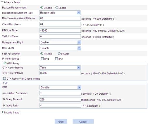
Figure 16 Configuring advanced settings for the clear type wireless service
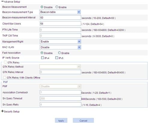
3. Configure the advanced settings for the clear type wireless service as described in Table 3.
4. Click Apply.
|
Item |
Description |
|
Beacon Measurement |
· Enable—Enable the beacon measurement function. · Disable—Disable the beacon measurement function. By default, the beacon measurement function is disabled. Beacon measurement, defined by 802.11k, provides a mechanism for APs and clients to measure the available radio resources. When this function is enabled, an AP periodically sends beacon requests to clients. Clients respond with beacon reports to inform the AP of the beacon measurement information they have collected. |
|
Beacon-measurement Type |
· Active—The AP sends a beacon measurement request to the client. Upon receiving the request, the client broadcasts probe requests on all supported channels, sets a measurement duration timer, and, at the end of the measurement duration, compiles all received beacons and probe responses into a measurement report. · Beacon-table—The AP sends a beacon measurement request to a client. Upon receiving the request, the client measures beacons and returns a report to the AP. The report contains all beacon information stored on the client. The client does not perform any additional measurements. · Passive—The AP sends a beacon measurement request to a client. Upon receiving the request, the client sets a measurement duration timer, and, at the end of the measurement duration, compiles all received beacons and probe responses into a measurement report. |
|
Beacon-measurement Interval |
The interval at which the AP sends beacon requests to clients. |
|
Client Max Users |
Maximum number of clients of an SSID to be associated with the same radio of the AP.
When the number of clients of an SSID to be associated with the same radio of the AP reaches the maximum, the SSID is automatically hidden. |
|
MAC VLAN |
· Enable—Enable the MAC VLAN feature for the wireless service. · Disable—Disable the MAC VLAN feature for the wireless service. |
|
Fast Association |
· Enable—Enable fast association. · Disable—Disable fast association. By default, fast association is disabled. When fast association is enabled, the device does not perform band navigation and load balancing calculations for associated clients. |
Configuring security settings for a clear type wireless service
1. Select Wireless Service > Access Service from the navigation tree.
2.
Click the ![]() icon for the target clear type wireless service in the list.
icon for the target clear type wireless service in the list.
The page for configuring security settings for the clear type wireless service appears.
Figure 17 Configuring security settings for the clear type wireless service
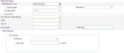
3. Configure the security settings for the clear type wireless service as described in Table 4.
4. Click Apply.
|
Item |
Description |
|
|
Authentication Type |
For the clear type wireless service, select Open-System only. |
|
|
Port Mode |
· mac-authentication—Perform MAC address authentication on users. See Figure 18 and Table 5. · mac-else-userlogin-secure—This mode is the combination of the mac-authentication and userlogin-secure modes, with MAC authentication having a higher priority. Upon receiving a non-802.1X frame, a port in this mode performs only MAC authentication. Upon receiving an 802.1X frame, the port performs MAC authentication and then, if MAC authentication fails, 802.1X authentication. See Figure 20 and Table 7. · mac-else-userlogin-secure-ext—This mode is similar to the mac-else-userlogin-secure mode, except that it supports multiple 802.1X and MAC authentication users on the port. · userlogin-secure—In this mode, port-based 802.1X authentication is performed for users. Multiple 802.1X authenticated users can access the port, but only one user can be online. See Figure 19 and Table 6. · userlogin-secure-or-mac—This mode is the combination of the userlogin-secure and mac-authentication modes, with 802.1X authentication having a higher priority. For a wireless user, 802.1X authentication is performed first. If 802.1X authentication fails, MAC authentication is performed. See Figure 20 and Table 7. · userlogin-secure-or-mac-ext—This mode is similar to the userlogin-secure-or-mac mode, except that it supports multiple 802.1X and MAC authentication users on the port. See Figure 20 and Table 7. · userlogin-secure-ext—In this mode, a port performs 802.1X authentication on users in macbased mode and supports multiple 802.1X users. See Figure 19 and Table 6.
There are multiple security modes. To remember them easily, follow these rules to understand part of the port security modes: · userLogin indicates port-based 802.1X authentication. · mac indicates MAC address authentication. · The authentication mode before Else is used preferentially. If the authentication fails, the authentication after Else may be used depending on the protocol type of the packets to be authenticated. · The authentication mode before Or and that after Or have the same priority. The device determines the authentication mode according to the protocol type of the packets to be authenticated. For wireless users, the 802.1X authentication mode is used preferentially. · userLogin together with Secure indicates MAC-based 802.1X authentication. · A security mode with Ext allows multiple 802.1X users to pass the authentication. A security mode without Ext allows only one 802.1X user to pass the authentication. |
|
|
Max User |
Set the maximum number of users that can be connected to the network through a specific port. |
|
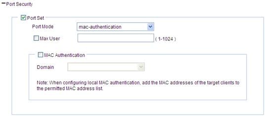
· To configure mac-authentication:
Figure 18 Configuring mac-authentication port security
|
Item |
Description |
|
Port Mode |
mac-authentication: MAC-based authentication is performed on access users. Select Wireless Service > Access Service from the navigation tree, and click MAC Authentication List to enter the page for configuring a MAC authentication list. On the page, enter the MAC address of the client. |
|
Max User |
Control the maximum number of users allowed to access the network through the port. |
|
MAC Authentication |
Select MAC Authentication. |
|
Domain |
Select an existing domain from the list. The default domain is system. To create a domain, select Authentication > AAA from the navigation tree, click the Domain Setup tab, and enter a new domain name in the Domain Name field. · The selected domain name applies to only the current wireless service, and all clients accessing the wireless service use this domain for authentication, authorization, and accounting. · Do not delete a domain name in use. Otherwise, the clients that access the wireless service are logged out. |
· To configure userlogin-secure/userlogin-secure-ext:

|
Item |
Description |
|
Port Mode |
· userlogin-secure—Perform port-based 802.1X authentication for access users. In this mode, multiple 802.1X authenticated users can access the port, but only one user can be online. · userlogin-secure-ext—Perform MAC-based 802.1X authentication for access users. In this mode, the port supports multiple 802.1X users. |
|
Max User |
Control the maximum number of users allowed to access the network through the port. |
|
Mandatory Domain |
Select an existing domain from the list. The default domain is system. To create a domain, select Authentication > AAA from the navigation tree, click the Domain Setup tab, and enter a new domain name in the Domain Name field. · The selected domain name applies to only the current wireless service, and all clients accessing the wireless service use this domain for authentication, authorization, and accounting. · Do not delete a domain name in use. Otherwise, the clients that access the wireless service will be logged out. |
|
Authentication Method |
· EAP—Use the EAP. With EAP authentication, the authenticator encapsulates 802.1X user information in the EAP attributes of RADIUS packets and sends the packets to the RADIUS server for authentication. It does not need to repackage the EAP packets into standard RADIUS packets for authentication. · CHAP—Use the CHAP. By default, CHAP is used. CHAP transmits usernames in plain text and passwords cipher text over the network. Therefore this method is safer. · PAP—Use the PAP. PAP transmits passwords in plain text. |
|
Handshake |
· Enable—Enable the online user handshake function so that the device can periodically send handshake messages to a user to check whether the user is online. By default, the function is enabled. · Disable—Disable the online user handshake function. |
|
Multicast Trigger |
· Enable—Enable the multicast trigger function of 802.1X to send multicast trigger messages to the clients periodically for initiating authentication. By default, the multicast trigger function is enabled. · Disable—Disable the 802.1X multicast trigger function.
For a WLAN, the clients can actively initiate authentication, or the AP can discover users and trigger authentication. Therefore, the ports do not need to send 802.1X multicast trigger messages periodically for initiating authentication. You are recommended to disable the multicast trigger function in a WLAN because the multicast trigger messages consume bandwidth. |
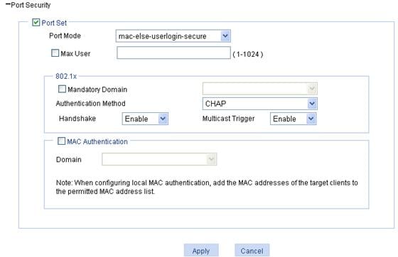
· To configure the other four port security modes:
|
Item |
Description |
|
Port Mode |
· mac-else-userlogin-secure—This mode is the combination of the mac-authentication and userlogin-secure modes, with MAC authentication having a higher priority. Upon receiving a non-802.1X frame, a port in this mode performs only MAC authentication; upon receiving an 802.1X frame, the port performs MAC authentication and then, if MAC authentication fails, 802.1X authentication. · mac-else-userlogin-secure-ext—This mode is similar to the mac-else-userlogin-secure mode, except that it supports multiple 802.1X and MAC authentication users on the port. · userlogin-secure-or-mac—This mode is the combination of the userlogin-secure and mac-authentication modes, with 802.1X authentication having a higher priority. For a wireless user, 802.1X authentication is performed first. If 802.1X authentication fails, MAC authentication is performed. · userlogin-secure-or-mac-ext—This mode is similar to the userlogin-secure-or-mac mode, except that it supports multiple 802.1X and MAC authentication users on the port. Select Wireless Service > Access Service from the navigation tree, and click MAC Authentication List to enter the page for configuring a MAC authentication list. On the page, enter the MAC address of the client. |
|
Max User |
Control the maximum number of users allowed to access the network through the port. |
|
Mandatory Domain |
Select an existing domain from the list. After a mandatory domain is configured, all 802.1X users accessing the port are forced to use the mandatory domain for authentication, authorization, and accounting. The default domain is system. To create a domain, select Authentication > AAA from the navigation tree, click the Domain Setup tab, and enter a new domain name in the Domain Name field. |
|
Authentication Method |
· EAP—Use the EAP. With EAP authentication, the authenticator encapsulates 802.1X user information in the EAP attributes of RADIUS packets and sends the packets to the RADIUS server for authentication. It does not need to repackage the EAP packets into standard RADIUS packets for authentication. · CHAP—Use the CHAP. By default, CHAP is used. CHAP transmits usernames in plain text and passwords in cipher text over the network. Therefore this method is safer. · PAP—Use the PAP. PAP transmits passwords in plain text. |
|
Handshake |
· Enable—Enable the online user handshake function so that the device can periodically send handshake messages to a user to check whether the user is online. By default, the function is enabled. · Disable—Disable the online user handshake function. |
|
Multicast Trigger |
· Enable—Enable the multicast trigger function of 802.1X to send multicast trigger messages to the clients periodically for initiating authentication. By default, the multicast trigger function is enabled. · Disable—Disable the 802.1X multicast trigger function.
For a WLAN, the clients can actively initiate authentication, or the AP can discover users and trigger authentication. Therefore, the ports do not need to send 802.1X multicast trigger messages periodically for initiating authentication. H3C recommends that you disable the multicast trigger function in a WLAN because the multicast trigger messages consume bandwidth. |
|
MAC Authentication |
Select MAC Authentication. |
|
Domain |
Select an existing domain from the list. The default domain is system. To create a domain, select Authentication > AAA from the navigation tree, click the Domain Setup tab, and enter a new domain name in the Domain Name field. · The selected domain name applies to only the current wireless service, and all clients accessing the wireless service use this domain for authentication, authorization, and accounting. · Do not delete a domain name in use. Otherwise, the clients that access the wireless service are logged out. |
Configuring crypto type wireless service
Configuring basic settings for a crypto type wireless service
1. Select Wireless Service > Access Service from the navigation tree.
2.
Click the ![]() icon for the target crypto type wireless service .
icon for the target crypto type wireless service .
The page for configuring a wireless service appears.
Figure 21 Configuring basic settings for the crypto type wireless service
3. Configure the basic settings for the crypto wireless service.
4. Click Apply.
Configuring advanced settings for a crypto type wireless service
1. Select Wireless Service > Access Service from the navigation tree.
2.
Click the ![]() icon for the target
crypto type wireless service in the list.
icon for the target
crypto type wireless service in the list.
The page for configuring advanced settings for the crypto type wireless service appears.
Figure 22 Configuring advanced settings for the crypto type wireless service
3. Configure the advanced settings for the crypto type wireless service as described in Table 8.
4. Click Apply.
|
|
NOTE: The service template settings cannot be modified after the service template is enabled. |
|
Item |
Description |
|
Beacon Measurement |
· Enable—Enable the beacon measurement function. · Disable—Disable the beacon measurement function. By default, the beacon measurement function is disabled. Beacon measurement, defined by 802.11k, provides a mechanism for APs and clients to measure the available radio resources. When this function is enabled, an AP periodically sends beacon requests to clients. Clients respond with beacon reports to inform the AP of the beacon measurement information they have collected. |
|
Beacon-measurement Type |
· Active—The AP sends a beacon measurement request to the client. Upon receiving the request, the client broadcasts probe requests on all supported channels, sets a measurement duration timer, and, at the end of the measurement duration, compiles all received beacons and probe responses into a measurement report. · Beacon-table—The AP sends a beacon measurement request to a client. Upon receiving the request, the client measures beacons and returns a report to the AP. The report contains all beacon information stored on the client. The client does not perform any additional measurements. · Passive—The AP sends a beacon measurement request to a client. Upon receiving the request, the client sets a measurement duration timer, and, at the end of the measurement duration, compiles all received beacons and probe responses into a measurement report. |
|
Beacon-measurement Interval |
The interval at which the AP sends beacon requests to clients. |
|
Client Max Users |
Maximum number of clients of an SSID to be associated with the same radio of the AP.
When the number of clients of an SSID to be associated with the same radio of the AP reaches the maximum, the SSID is automatically hidden. |
|
PTK Life Time |
Set the PTK lifetime. A PTK is generated through a four-way handshake. |
|
TKIP CM Time |
Set the TKIP countermeasure time. By default, the TKIP countermeasure time is 0 seconds, that is, the TKIP countermeasure policy is disabled. If the TKIP countermeasure time is set to a value other than 0, the TKIP countermeasure policy is enabled. MIC is designed to avoid hacker tampering. It uses the Michael algorithm and is extremely secure. When failures occur to MIC, the data may have been tampered, and the system may be under attack. In this case, TKIP will enable the countermeasure policy to prevent hackers from attacking. With the countermeasure policy enabled, if more than two MIC failures occur within the specified time, the TKIP disassociates all connected wireless clients and no new associations are allowed within the TKIP countermeasure time. |
|
Management Right |
Whether online clients can manage the device in the Web interface. |
|
MAC VLAN |
· Enable—Enable the MAC VLAN feature for the wireless service. · Disable—Disable the MAC VLAN feature for the wireless service. |
|
Fast Association |
· Enable—Enable fast association. · Disable—Disable fast association. By default, fast association is disabled. When fast association is enabled, the device does not perform band navigation calculations for associated clients. |
|
IP Verify Source |
Source address verification: · IPv4—Enable IPv4 source address verification. · IPv6—Enable IPv6 source address verification. By default, source address verification is disabled. |
|
GTK Rekey Method |
An AP generates a group transient key (GTK) and sends the GTK to a client during the authentication process between an AP and the client through group key handshake/the 4-way handshake. The client uses the GTK to decrypt broadcast and multicast packets. · If Time is selected, the GTK is refreshed after a specified period of time. · If Packet is selected, the GTK is refreshed after a specified number of packets are transmitted. By default, the GTK rekeying method is time-based, and the interval is 86400 seconds. |
|
GTK User Down Status |
Enable refreshing the GTK when some client goes offline. By default, the GTK is not refreshed when a client goes off-line. |
Configuring management frame protection for a crypto-type wireless service
Perform this task to enable an AP to protect management frames, including deauthentication frames, deassociation frames, and some robust action frames.
Management frame protection uses the PTK encrypt method to ensure privacy, integrity, and replay protection of unicast management frames.
For multicast and broadcast management frames, this feature uses Broadcast Integrity Protocol (BIP) to ensure integrity and replay protection. BIP adds the Management MIC IE (MME) field to the end of the management frames to protect their privacy.
If management frame protection is enabled, the AP uses SA Query to secure connections with clients.
SA Query includes active SA Query and passive SA Query.
· Active SA Query
If the AP receives spoofing association or reassociation requests, this mechanism can prevent the AP from responding to clients.
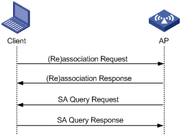
As shown in Figure 23, active SA Query operates as follows:
a. The client sends an association or a reassociation request to the AP.
b. Upon receiving the request, the AP sends a response to inform the client that the request is denied and the client can associate later. The response contains an association comeback time.
c. The AP sends an SA Query request to the client.
¡ If the AP receives an SA Query response within the timeout time, it determines that the client is online.
¡ If the AP receives no SA Query response within the timeout time, it resends the request. If the AP receives an SA Query response within the retransmission time, it determines that the client is online.
¡ If the client is online, the AP does not respond to any association or reassociation request from the client within the association comeback time.
¡ If the AP receives no SA Query response within the retransmission time, it determines that the client is offline. The AP allows the client to reassociate with it.
· Passive SA Query.
If a client receives unencrypted deassociation or deauthentication frames with failure code 6 or 7, this mechanism can prevent the client from going offline abnormally.
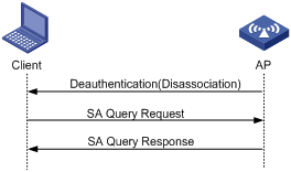
As shown in Figure 24, passive SA Query operates as follows:
a. The client triggers the SA Query mechanism upon receiving an unencrypted deassociation or deauthentication frame.
b. The client sends an SA Query request to the AP.
c. The AP responds with an SA Query response.
d. The client determines the AP is online because it receives the SA Query response. The client does not go offline.
To configure management frame protection:
2. Select Wireless Service > Access Service from the navigation tree.
3.
Click the ![]() icon for the target
crypto-type wireless service.
icon for the target
crypto-type wireless service.
Figure 25 Configuring management frame protection for a crypto-type wireless service
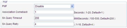
4. Configure management frame protection for a crypto-type wireless service as described in Table 9.
5. Click Apply.
|
Item |
Description |
|
PMF |
Management frame protection status: · Disabled—All clients can associate with the AP. The AP does not protect management frames in communications. · Optional—All clients can associate with the AP. The AP protects management frames from clients supporting PMF. · Mandatory—Clients supporting PMF can associate with the AP. The AP protects management frames from these clients. Clients not supporting PMF cannot associate with the AP. By default, PMF is disabled. NOTE: You can only configure management frame protection on a service template whose: · Authentication type is PSK or 802.1X. · Cipher suite is AES. · Security IE is WPA2. |
|
Association Comeback |
The AP does not respond to any association or reassociation request from the client within the association comeback time. |
|
SA Query Timeout |
If the AP receives no SA Query response within the timeout time, it resends the request. |
|
SA Query Retry |
The retransmission time for an AP to retransmit SA Query requests. |
Configuring security settings for a crypto type wireless service
1. Select Wireless Service > Access Service from the navigation tree.
2.
Click the ![]() icon for the target crypto type wireless service in the list.
icon for the target crypto type wireless service in the list.
The page for configuring advanced settings for the crypto type wireless service appears.
Figure 26 Configuring security settings for the crypto type wireless service
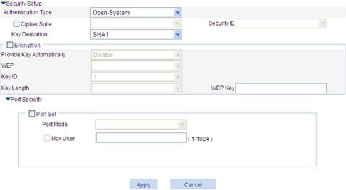
3. Configure the security settings for the crypto type wireless service as described in Table 10.
4. Click Apply.
|
Item |
Description |
|
Authentication Type |
Link authentication method, which can be: · Open-System—No authentication. With this authentication mode enabled, all the clients will pass the authentication. · Shared-Key—The two parties must have the same shared key configured for this authentication mode. You can select this option only when WEP encryption mode is used. · Open-System and Shared-Key—You can select both open-system and shared-key authentication.
WEP encryption can be used together with open system and shared-key authentication. · Open system authentication—When you use this authentication mode, a WEP key is used for encryption only. If the two parities do not use the same key, a wireless link can still be established, but all data is discarded. · Shared-key authentication—When this authentication mode is used, a WEP key is used for both authentication and encryption. If the two parties do not use the same key, the client cannot pass the authentication and cannot access the wireless network. |
|
Cipher Suite |
Encryption mechanisms supported by the wireless service, which can be: · AES—AES encryption algorithm. · TKIP—Encryption mechanism based on the RC4 algorithm and dynamic key management. · AES and TKIP—You can select both AES and TKIP encryption. |
|
Security IE |
Wireless service type (IE information carried in the beacon or probe response frame): · WPA—Wi-Fi Protected Access. · RSN—An RSN is a security network that allows only the creation of robust security network associations (RSNAs). It provides greater protection than WEP and WPA. · WPA and RSN—You can select both WPA and RSN. |
|
Key Derivation |
Specify the hash algorithm used to generate PTK and GTK based on PMK. Key derivation type: · SHA1—Supports the HMAC-SHA1 hash algorithm. · SHA256—Supports the HMAC-SHA256 hash algorithm. · SHA1 and SHA256—Supports the HMAC-SHA1 and the HMAC-SHA256 hash algorithms. By default, the key derivation type is SHA1. NOTE: The key derivation type takes effect only when PSK or 802.1X authentication is used. |
|
Encryption |
|
|
Provide Key Automatically |
· Enable—A WEP key is assigned dynamically. · Disable—A static WEP key is used. By default, a static WEP key is used. When you enable this function, the WEP option is automatically set to wep104.
· Use this function together with 802.1X authentication. · With dynamic WEP encryption configured, the WEP key used to encrypt unicast frames is negotiated between client and server. If the WEP default key is configured, the WEP default key is used to encrypt multicast frames. If not, the device randomly generates a multicast WEP key. |
|
WEP |
· wep40—WEP40 key option. · wep104—WEP104 key option. · wep128—WEP128 key option. |
|
Key ID |
Configure the key index, which can be: · 1—Key index 1. · 2—Key index 2. · 3—Key index 3. · 4—Key index 4. There are 4 static keys in WEP. The key index can be 1, 2, 3, or 4. The key corresponding to the specified key index will be used for encrypting and decrypting broadcast and multicast frames. |
|
Key Length |
Key length. · For wep40, the key is a string of 5 alphanumeric characters or a 10-digit hexadecimal number. · For wep104, the key is a string of 13 alphanumeric characters or a 26-digit hexadecimal number. · For wep128, the key is a string of 16 alphanumeric characters or a 32-digit hexadecimal number. |
|
WEP Key |
Configure the WEP key. |
|
Port Security |
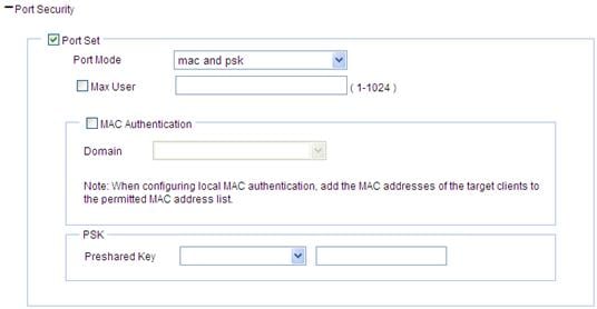
See Table 4. Parameters such as authentication type and encryption type determine the port mode. For more information, see Table 13. After you select the Cipher Suite option, the following three port security modes are added: · mac and psk—MAC-based authentication must be performed on access users first. If MAC-based authentication succeeds, an access user has to use the pre-configured PSK to negotiate with the device. Access to the port is allowed only after the negotiation succeeds. See Figure 27 and Table 11. · psk—An access user must use the pre-shared key (PSK) that is pre-configured to negotiate with the device. The access to the port is allowed only after the negotiation succeeds. See Figure 28 and Table 12. · userlogin-secure-ext—Perform MAC-based 802.1X authentication for access users. In this mode, the port supports multiple 802.1X users. See Figure 19 and Table 6. |
· To configure mac and psk:
Figure 27 Configuring mac and psk port security
|
Item |
Description |
|
Port Mode |
mac and psk: MAC-based authentication must be performed on access users first. If MAC-based authentication succeeds, an access user has to use the pre-configured PSK to negotiate with the device. Access to the port is allowed only after the negotiation succeeds. Select Wireless Service > Access Service from the navigation tree, and click MAC Authentication List to enter the page for configuring a MAC authentication list. On the page, enter the MAC address of the client. |
|
Max User |
Control the maximum number of users allowed to access the network through the port. |
|
MAC Authentication |
Select MAC Authentication. |
|
Domain |
Select an existing domain from the list. The default domain is system. To create a domain, select Authentication > AAA from the navigation tree, click the Domain Setup tab, and enter a new domain name in the Domain Name field. · The selected domain name applies to only the current wireless service, and all clients accessing the wireless service use this domain for authentication, authorization, and accounting. · Do not delete a domain name in use. Otherwise, the clients that access the wireless service will be logged out. |
|
Preshared Key |
· pass-phrase—Enter a PSK in the form of a character string. · raw-key—Enter a PSK in the form of a hexadecimal number. |
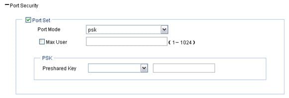
· To configure PSK:
Figure 28 Configuring psk port security
|
Item |
Description |
|
Port Mode |
psk: An access user must use the pre-shared key (PSK) that is pre-configured to negotiate with the device. The access to the port is allowed only after the negotiation succeeds. |
|
Max User |
Control the maximum number of users allowed to access the network through the port. |
|
Preshared Key |
· pass-phrase—Enter a PSK in the form of a character string. · raw-key—Enter a PSK in the form of a hexadecimal number. |
· To configure userlogin-secure-ext:
Perform the configurations as shown inTable 5Figure 19.
Security parameter dependencies
For a clear-type wireless service or crypto-type wireless service, the security parameter dependencies are described in Table 13.
Table 13 Security parameter dependencies
|
Service type |
Authentication mode |
Encryption type |
Security IE |
WEP encryption/key ID |
Port mode |
|
Clear |
Open-System |
Unavailable |
Unavailable |
Unavailable |
· mac-authentication · mac-else-userlogin-secure · mac-else-userlogin-secure-ext · userlogin-secure · userlogin-secure-ext · userlogin-secure-or-mac · userlogin-secure-or-mac-ext |
|
Crypto |
Open-System |
Selected |
Required |
WEP encryption is available The key ID can be 1, 2, 3, or 4 |
· mac and psk · psk · userlogin-secure-ext |
|
Unselected |
Unavailable |
WEP encryption is required The key ID can be 1, 2, 3, or 4 |
· mac-authentication · userlogin-secure · userlogin-secure-ext |
||
|
Shared-Key |
Unavailable |
Unavailable |
WEP encryption is required The key ID can be 1, 2, 3, or 4 |
mac-authentication |
|
|
Open-System and Shared-Key |
Selected |
Required |
WEP encryption is required The key ID can be 2, 3, or 4 |
· mac and psk · psk · userlogin-secure-ext |
|
|
Unselected |
Unavailable |
WEP encryption is required The key ID can be 1, 2, 3, or 4 |
· mac-authentication · userlogin-secure · userlogin-secure-ext |
Binding an AP radio to a wireless service
1. Select Wireless Service > Access Service from the navigation tree.
2.
Click the ![]() icon for the target wireless service to enter the page as shown
in Figure 29.
icon for the target wireless service to enter the page as shown
in Figure 29.
Figure 29 Binding an AP radio to a wireless service

3. Select the AP radio to be bound.
4. Click Bind.
Enabling a wireless service
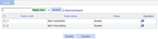
1. Select Wireless Service > Access Service from the navigation tree to enter the page as shown in Figure 30.
Figure 30 Enabling a wireless service
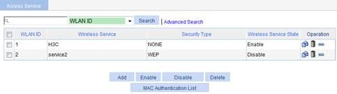
2. Select the wireless service to be bound.
3. Click Enable.
Enabling a radio
Select Radio > Radio Setup from the navigation tree to enter the radio setup page and make sure the radio is enabled.
Configuring WDS service
Configuring WDS service
1. Select Wireless Service > WDS from the navigation tree.
2. Click the WDS Setup tab to enter the WDS setup page.
3.
Click the ![]() icon for the radio
mode to be configured in the Operation column to enter the WDS
Setup page.
icon for the radio
mode to be configured in the Operation column to enter the WDS
Setup page.
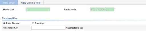
4. Configure WDS as described in Table 14.
5. Click Apply.
|
Item |
Description |
|
Radio Unit |
Radio ID, 1 or 2. |
|
Radio Mode |
Display the radio mode, which depends on your radio type. |
|
Pass Phrase |
Specify the pass phrase format, indicating that you must enter the pre-shared key in a string. |
|
Raw Key |
Specify the raw key format, indicating that you must enter the pre-shared key in a hex number. |
|
Preshared Key |
Set the pre-shared key: · A string of 8 to 64 characters that can be displayed if the Pass Phrase option is selected. · A valid 64-digit hex number if the Raw Key option is selected. |
Configuring a neighbor MAC address
If no neighbor MAC address is configured for an AP, the AP can establish a WDS link with any other AP; if a neighbor MAC address is configured for an AP, the AP can establish a WDS link with only the specified peer AP.
1. Select Wireless Service > WDS from the navigation tree.
2.
Click the ![]() icon for the radio mode to enter the page for configuring a neighbor MAC address.
icon for the radio mode to enter the page for configuring a neighbor MAC address.
Figure 33 Configuring a neighbor MAC address
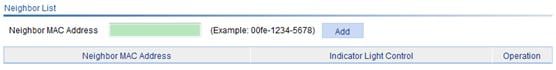
3. Enter the MAC address in the Neighbor MAC Address field, and click Add.
4. Click Apply.
Configuring advanced WDS settings
1. Select Wireless Service > WDS from the navigation tree.
2. Click the WDS Setup tab.
3.
Click the ![]() icon for the radio
mode to be configured .
icon for the radio
mode to be configured .
The page for configuring advanced WDS appears.
Figure 34 Configuring advanced WDS
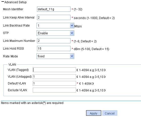
4. Configure advanced WDS settings as described in Table 15.
5. Click Apply.
|
Item |
Description |
|
Mesh Identifier |
Set the mesh ID. The default mesh identifier of a device depends on its radio mode. |
|
Link Keep Alive Interval |
Configure the mesh link keep-alive interval. |
|
Link Backhaul Rate |
Configure the backhaul radio rate. |
|
STP |
The following loop types may exist in a WDS network:
When a loop exists in the network, you can block redundant links to remove the loop by STP, and can provide link backup when a WDS link fails. Set STP. · Enable—Enable STP. · Disable—Disable STP. By default, STP is enabled. This configuration is applicable to only WLAN-mesh interfaces, and global STP configuration (see "Configuring global WDS") is applicable to all interfaces. |
|
Link Maximum Number |
Set the maximum number of WDS links allowed.
If an AP needs to establish more than two WDS links, set this number as required. |
|
Link Hold RSSI |
Set the link hold RSSI. This is the minimum RSSI required to establish and hold a link. Therefore, the minimum RSSI must be ensured. Otherwise, the error rate can be very high and the link performance will deteriorate. |
|
ratemode |
· fixed—The rate adopted is of a fixed value. It is the maximum rate of the current radio. · realtime—The rate adopted changes with the link quality, that is, the rate changes with the change of the RSSI of the current radio. The fixed mode is adopted by default. |
|
VLAN (Tagged) |
Enter the ID of the VLAN whose packets are to be sent tagged. VLAN (Tagged) indicates that the port sends the traffic of the VLAN without removing the VLAN tag. |
|
VLAN (Untagged) |
Enter the ID of the VLAN whose packets are to be sent untagged. VLAN (Untagged) indicates that the ports send the traffic of the VLAN with the VLAN tag removed. |
|
Default VLAN |
Set the default VLAN. By default, the default VLAN of all ports is VLAN 1. After you set the new default VLAN, VLAN 1 is the ID of the VLAN whose packets are to be sent untagged. |
|
Exclude VLAN |
Remove the IDs of the VLANs whose packets are to be sent untagged and tagged. |
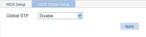
Configuring global WDS
1. Select Wireless Service > WDS from the navigation tree.
2. Select the WDS Global Setup tab to enter the WDS Global Setup page.
Figure 35 Configuring WDS globally
3. Configure global WDS settings as described in Table 16.
4. Click Apply.
|
Item |
Description |
|
Global STP |
· Enable—Enable STP globally. · Disable—Disable STP globally. By default, STP is disabled globally. |
Configuring a working channel
You can configure a working channel in the following two ways:
· Manual—To establish a mesh link between the MAP and MPP, specify a working channel for the radios of the MAP and the MPP, and the working channel on the radio of the MAP should be consistent with that on the MPP.
· Auto—Set the working channels on the MPP and MAP to auto so that working channels are automatically negotiated when a WDS link is to be established between the MPP and MAP.
A radio enabled with automatic dynamic frequency selection (DFS) and WDS works in a non-radar channel.
No matter which method is used, as long as an AP detects radar signals on its working channel, the AP and any other AP that establish a mesh/WDS link switch to another available working channel.
In some countries, most available channels on the 802.11a band are radar channels, so H3C recommends you use the auto mode to establish mesh/WDS links on the 802.11a band.
When you select auto-DFS, if no WDS link is established, a temporary working channel is automatically selected for a radio. The validation time of the temporary working channel is from 10 to 20 seconds. After the temporary working channel times out, a new temporary working channel will be selected. The information of channel switching between the automatically selected and temporary working channels is saved in the channel switching information of the radio.
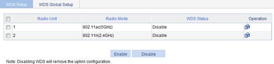
Enabling WDS service
1. Select Wireless Service > WDS from the navigation tree.
2. Select the WDS Setup tab to enter the WDS setup page.
Figure 36 Enabling WDS service
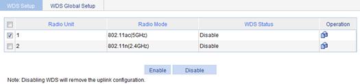
3. Select the radio for which WDS is to be enabled.
4. Click Enable.
Configuring the repeater service
To configure the repeater service, configure WDS and wireless access service on the same radio of an AP, and configure the radio to use a fixed channel.
· For how to configure wireless access service for the repeater, see "
· The interface types and output information vary by device model and radio type.
· Configuring access service."
· For how to configure WDS for the repeater, see "Configuring WDS service."
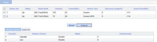
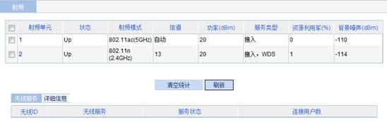
After completing the above configurations, select Summary > Radio from the navigation tree to enter the page shown in Figure 37. On the page, you can see that the 802.11n radio of the repeater provides both access and WDS services.
Wireless access configuration examples
Wireless service configuration example
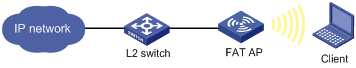
Network requirements
As shown in Figure 38, enable the client to access the internal network resources at any time. The AP provides plain-text wireless access service with SSID service1. 802.11n is adopted.

Configuring the AP
1. Assign an IP address to the fat AP:
a. Select Network > VLAN to create a VLAN on the fat AP.
b. Select Device > Interface Management to assign an IP address to the VLAN interface.
2. Configure a wireless service:
a. Select Wireless Service > Access Service from the navigation tree.
b. Click Add.
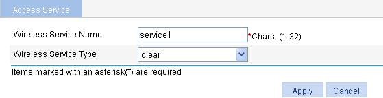
c. On the page that appears, enter the service name service1, select the wireless service type clear, and click Apply.
Figure 39 Creating a wireless service
3. Bind an AP radio to a wireless service:
a. Select Wireless Service > Access Service from the navigation tree.
b. Click the ![]() icon for the wireless service service1 to
enter the page as shown in Figure 40.
icon for the wireless service service1 to
enter the page as shown in Figure 40.
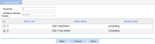
c. Select the box with radio mode 802.11n.
d. Click Bind.
Figure 40 Binding an AP radio to a wireless service
4. Enable the wireless service:
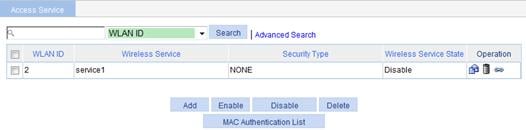
a. Select Wireless Service > Access Service from the navigation tree to enter the page for enabling wireless service.
b. Select the service1 box.
c. Click Enable.
Figure 41 Enabling the wireless service
5. Optional: Enable 802.11n radio (By default, 802.11n radio is enabled.)
Select Radio > Radio from the navigation tree to enter the Radio page. Make sure 802.11n radio is enabled.
Figure 42 Enabling 802.11n radio
Verifying the configuration
· The client can successfully associate with the AP and access the WLAN network.
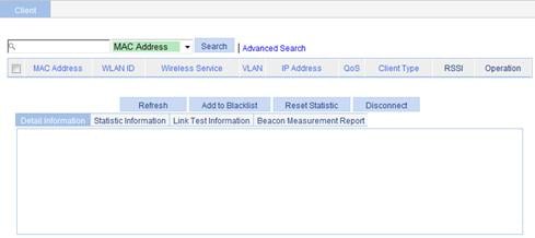
· You can view the online clients on the page that you enter by selecting Summary > Client from the navigation tree.
Figure 43 Viewing the online clients
Configuration guidelines
Follow these guidelines when you configure a wireless service:
· Select a correct district code.
· Make sure the radio unit is enabled.
Access service-based VLAN configuration example
Network requirements
An AP can provide multiple wireless access services. Different wireless access services can use different wireless security policies, and can be bound to different VLANs to implement wireless access user isolation.
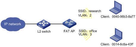
As shown in Figure 44, configure wireless VLANs to satisfy the following requirements:
· Set up a wireless access service named research, and configure it to use the PSK authentication. Clients that access the wireless network are in VLAN 2.
· Set up a wireless access service named office, and configure it to use the clear text authentication. Clients that access the wireless network are in VLAN 3.
Configuring the AP
1. Configure the fat AP interface:
a. Assign an IP address to the fat AP:
¡ Select Network > VLAN to create a VLAN on the fat AP.
¡ Select Device > Interface Management to assign an IP address to the VLAN interface.
b. Configure the link type of the Ethernet interface on the fat AP as trunk, and allow packets from VLAN 2 and VLAN 3. For more information, see "Configuring VLANs."
2. Configure a wireless service named research:
a. Select Wireless Service > Access Service from the navigation tree.
b. Click Add.
c. On the page that appears, enter the service name research and select the wireless service type crypto, and click Apply.
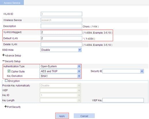
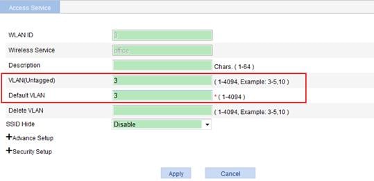
d. On the page that appears, enter 2 in the VLAN (Untagged) field, enter 2 in the Default VLAN field, enter 1 in the Delete VLAN field, select Cipher Suite and AES and TKIP, and click Apply.
Before you perform these VLAN settings, select Network > VLAN to create VLAN 2 first.
Figure 45 Setting the VLANs
For PSK-related configuration, see "WPA-PSK authentication configuration example." You can strictly follow the configuration example to configure the PSK configuration.
3. Configure a wireless service named office:
a. Select Wireless Service > Access Service from the navigation tree.
b. Click Add.
c. On the page that appears, enter the service name office, select the wireless service type clear, and click Apply.
d. On the page that appears, enter 3 in the VLAN (Untagged) field, enter 3 in the Default VLAN field, enter 1 in the Delete VLAN field, and click Apply.
Before you perform these VLAN settings, select Network > VLAN to create VLAN 3 first.
Figure 46 Setting VLANs
For wireless access configuration, see "Wireless access configuration examples." You can follow the wireless access configuration examples to configure wireless access.
Verifying the configuration
· The client can successfully associate with the AP and access the WLAN network.
· You can view the online clients on the page that you enter by selecting Summary > Client from the navigation tree.
The page shows that the client 984b-4ad4-3f24, which accesses the SSID office, is in VLAN 3, while the client 984b-4ad4-3fd4, which accesses the SSID research, is in VLAN 2. The two clients are in different VLANs, so they cannot access each other.
WPA-PSK authentication configuration example
Network requirements
As shown in Figure 47, configure the client to access the wireless network by passing PSK authentication. The WPA-PSK key configuration on the client is the same as that on the AP, that is, 12345678.
Configuring the AP
1. Assign an IP address to the fat AP:
a. Select Network > VLAN to create a VLAN on the fat AP.
b. Select Device > Interface Management to assign an IP address to the VLAN interface.
2. Configure a wireless service:
a. Select Wireless Service > Access Service from the navigation tree.
b. Click Add.
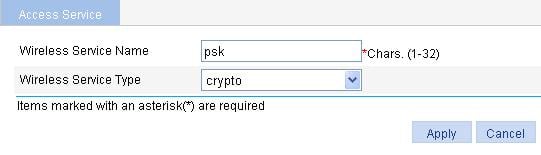
c. On the page that appears, enter the service name psk, select the wireless service type crypto, and click Apply.
Figure 48 Creating a wireless service
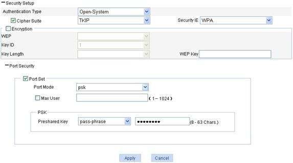
3. Configure PSK authentication:
After you create a wireless service, you will enter the wireless service configuration page.
a. In the Security Setup area, select the Open-System from the Authentication Type list.
b. Select the Cipher Suite box, select TKIP (select an encryption type as needed), and select WPA from the Security IE list.
c. Select the Port Set option, and select psk from the Port Mode list.
d. Select pass-phrase from the Preshared Key list, and enter the key ID 12345678.
e. Click Apply.
Figure 49 Configuring security settings
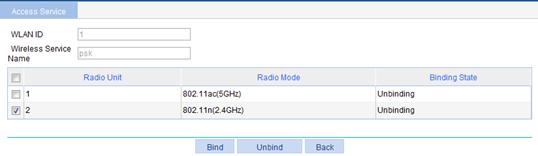
4. Bind an AP radio to a wireless service:
a. Select Wireless Service > Access Service from the navigation tree.
b. Click the ![]() icon for the wireless service psk to enter the
page as shown in Figure 50.
icon for the wireless service psk to enter the
page as shown in Figure 50.
c. Select the box with radio mode 802.11n.
d. Click Bind.
Figure 50 Binding an AP radio to a wireless service
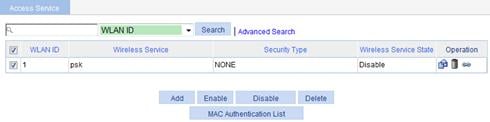
5. Enable the wireless service:
a. Select Wireless Service > Access Service from the navigation tree.
b. On the page that appears, select the psk box and click Enable.
Figure 51 Enabling the wireless service
6. Enable 802.11n radio (By default, 802.11n radio is enabled. Therefore, this step is optional. )
Select Radio > Radio from the navigation tree to enter the Radio page. Make sure 802.11n radio is enabled.
Configuring the client
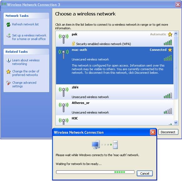
1. Launch the client, and refresh the network list.
2. Select the configured service in Choose a wireless network (psk in this example).
3. Click Connect.
4. In the popup dialog box, enter the key (12345678 in this example).
5. Click Connect.
Figure 52 Configuring the client
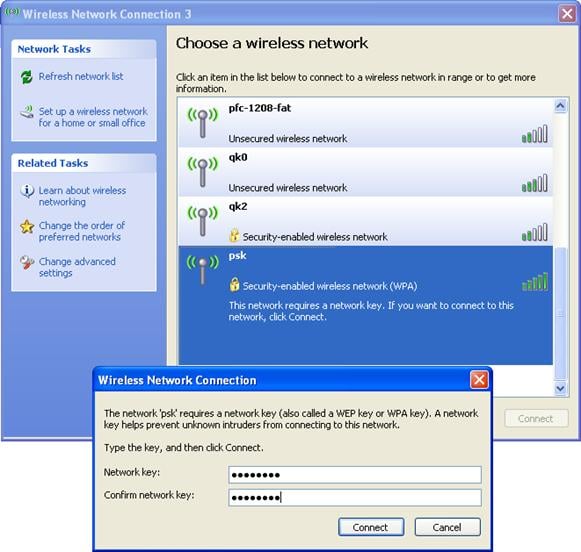
The client has the same pre-shared PSK key as the AP, so the client can associate with the AP.
Figure 53 The client is associated with the AP
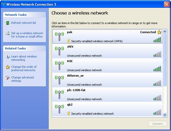
Verifying the configuration
· The client can successfully associate with the AP and can access the WLAN network.
· You can view the online clients by selecting Summary > Client from the navigation tree.
Local MAC authentication configuration example
Network requirements
As shown in Figure 54, perform MAC authentication on the client.
Configuring the AP
1. Assign an IP address to the fat AP:
a. Select Network > VLAN to create a VLAN on the fat AP.
b. Select Device > Interface Management to assign an IP address to the VLAN interface.
2. Configure a wireless service:
a. Select Wireless Service > Access Service from the navigation tree.
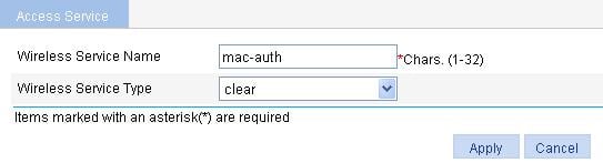
b. Click Add.
c. On the page that appears, set the service name to mac-auth, select the wireless service type clear, and click Apply.
Figure 55 Creating a wireless service
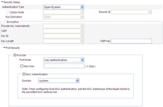
3. Configure local MAC authentication:
After you have created a wireless service, you enter the wireless service configuration page.
a. In the Security Setup area, select the Open-System from the Authentication Type list.
b. Select the Port Set box, and select mac-authentication from the Port Mode list.
c. Select the MAC Authentication box, and select system from the Domain list.
To create a domain, select Authentication > AAA from the navigation tree, click the Domain Setup tab, and enter a domain name in the Domain Name field.
d. Click Apply.
Figure 56 Configuring security settings

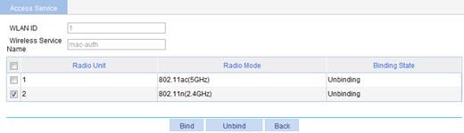
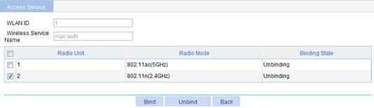
4. Bind an AP radio to a wireless service:
a. Select Wireless Service > Access Service from the navigation tree.
b. Click the ![]() icon for the wireless service mac-auth to
enter the page as shown in Figure 57.
icon for the wireless service mac-auth to
enter the page as shown in Figure 57.
c. Select the box with radio mode 802.11n.
d. Click Bind.
Figure 57 Binding an AP radio to a wireless service
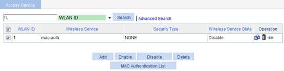
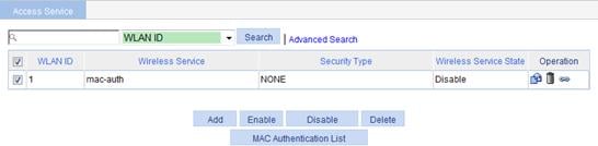
5. Enable the wireless service:
a. Select Wireless Service > Access Service from the navigation tree to enter the page as shown in Figure 58.
b. Select the mac-auth box.
c. Click Enable.
Figure 58 Enabling the wireless service
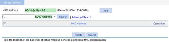
6. Configure a MAC authentication list:
a. Select Wireless Service > Access Service from the navigation tree.
b. Click MAC Authentication List to enter the page as shown in Figure 59.
c. Add a local user in the MAC Address field. 00-14-6c-8a-43-ff is used in this example.
d. Click Add.
Figure 59 Adding a MAC authentication list
7. Enable 802.11n radio (By default, 802.11n radio is enabled. Therefore, this step is optional. )
Select Radio > Radio from the navigation tree to enter the Radio page. Make sure 802.11n is enabled.
Configuring the client
1. Launch the client, and refresh the network list.
2. Select the configured service in Choose a wireless network (mac-auth in this example).
3. Click Connect.
If the MAC address of the client is in the MAC address list, the client can pass the MAC authentication and access the wireless network.
Figure 60 Configuring the client
Verifying the configuration
1. The client can pass authentication and access the WLAN network.
2. You can view the online clients on the page that you enter by selecting Summary > Client from the navigation tree.
Remote MAC authentication configuration example
Network requirements
Perform remote MAC authentication on the client:
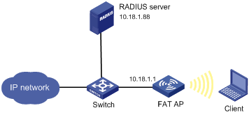
· A RADIUS server (an IMC server for authentication, authorization, and accounting) is required. On the RADIUS server, the client’s username and password (the MAC address of the client) and the shared key expert have been configured. The IP address of the RADIUS server is 10.18.1.88.
· The IP address of the AP is 10.18.1.1. On the AP, configure the shared key for communication with the RADIUS server as expert, and configure the AP to remove the domain name of a username before sending it to the RADIUS server.
Figure 61 Network diagram

Configuring the AP
1. Assign an IP address to the fat AP:
a. Select Network > VLAN to create a VLAN on the fat AP.
b. Select Device > Interface Management to assign an IP address to the VLAN interface.
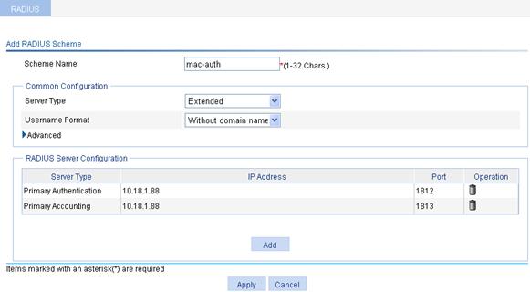
2. Configure a RADIUS scheme:
a. Select Authentication > RADIUS from the navigation tree.
b. Click Add.
c. On the page that appears, add two servers in the RADIUS Server Configuration area, and specify the key expert.
d. Enter mac-auth in the Scheme Name field.
e. Select Extended as the server type.
f. Select Without domain name for Username Format.
g. Click Apply.
3. Configure AAA:
a. From the navigation tree, select Authentication > AAA.
b. Optional: On the Domain Setup tab, create a new ISP domain.
This example uses the default domain system.
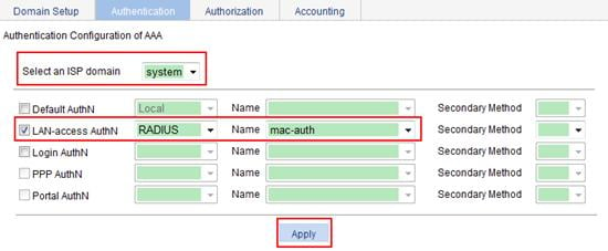
c. On the Authentication tab, select the ISP domain system, select the LAN-access AuthN box, select the authentication mode RADIUS, select the authentication scheme mac-auth from the Name list, and click Apply.
Figure 63 Configuring the AAA authentication method for the ISP domain
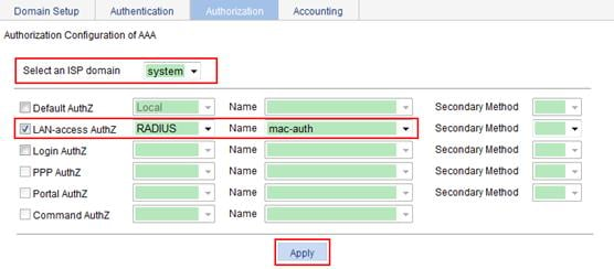
d. On the Authorization tab, select the ISP domain system, select the LAN-access AuthZ box, select the authorization mode RADIUS, select the authorization scheme mac-auth from the Name list, and click Apply.
Figure 64 Configuring the AAA authorization method for the ISP domain
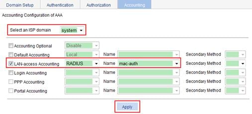
e. On the Accounting tab, select the ISP domain system, select the Accounting Optional box, and select Enable from the Accounting Optional list, select the LAN-access Accounting box, select the accounting method RADIUS, select the accounting scheme mac-auth from the Name list, and click Apply.
Figure 65 Configuring the AAA accounting method for the ISP domain
4. Configure wireless service:
a. Select Wireless Service > Access Service from the navigation tree.
b. Click Add.
c. On the page that appears, set the wireless service name to mac-auth, select the wireless service type clear, and click Apply.
Figure 66 Creating a wireless service
5. Configure MAC authentication:
After you create a wireless service, you enter the wireless service configuration page.
a. In the Security Setup area, select the Open-System from the Authentication Type list.
b. Select the Port Set box, and select mac-authentication from the Port Mode list.
c. Select the MAC Authentication box, and select system from the Domain list.
d. Click Apply.
Figure 67 Configuring security settings
6. Bind an AP radio to a wireless service:
a. Select Wireless Service > Access Service from the navigation tree.
b. Click the corresponding ![]() icon at the right side of the wireless service mac-auth to enter the page as shown
in Figure 68.
icon at the right side of the wireless service mac-auth to enter the page as shown
in Figure 68.
c. Select the radio mode 802.11n.
d. Click Bind.
Figure 68 Binding an AP radio to a wireless service
7. Enable the wireless service:
a. Select Wireless Service > Access Service from the navigation tree.
b. On the page that appears, select the mac-auth box and click Enable.
Figure 69 Enabling the wireless service
8. Enable 802.11n radio (By default, 802.11n radio is enabled. Therefore, this step is optional. )
Select Radio > Radio from the navigation tree to enter the Radio page. Make sure 802.11n is enabled.
Configuring the RADIUS server
For more information about how to configure the RADIUS server, see related IMC guides.
Remote 802.1X authentication configuration example
Network requirements
Perform remote 802.1X authentication on the client.
· A RADIUS server (an IMC server for authentication, authorization, and accounting) is required. On the RADIUS server, the client’s username user and password dot1x, and the shared key expert have been configured. The IP address of the RADIUS server is 10.18.1.88.
· The IP address of the AP is 10.18.1.1. On the AP, configure the shared key as expert, and configure the AP to remove the domain name of a username before sending it to the RADIUS server.
Figure 70 Network diagram
Configuring the AP
1. Assign an IP address to the fat AP:
a. Select Network > VLAN to create a VLAN on the fat AP.
b. Select Device > Interface Management to assign an IP address to the VLAN interface.
a. Select Authentication > RADIUS from the navigation tree.
b. Click Add.
c. On the page that appears, add two servers in the RADIUS Server Configuration, and specify the key expert.
d. Enter 802.1x in the Scheme Name field.
e. Select the server type Extended, and select Without domain name from the Username Format list.
f. Click Apply.

a. Select Authentication > AAA from the navigation tree.
b. Optional: On the Domain Setup tab, create a new ISP domain.
This example uses the default domain system.
c. On the Authentication tab, select the ISP domain system, select the LAN-access AuthN box, select the authentication mode RADIUS, select the authentication scheme 802.1x from the Name list, and click Apply.
Figure 72 Configuring the AAA authentication method for the ISP domain
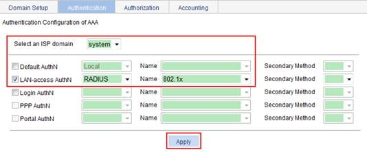
d. On the Authorization tab, select the domain name system, select the LAN-access AuthZ box, select the authorization mode RADIUS, select the authorization scheme 802.1x from the Name list, and click Apply.
Figure 73 Configuring the AAA authorization method for the ISP domain

e. On the Accounting tab, select the ISP domain name system, select the Accounting Optional box and then select Enable from the Accounting Optional list, select the LAN-access Accounting box, select the accounting method RADIUS, select the accounting scheme 802.1x from the Name list, and click Apply.
Figure 74 Configuring the AAA accounting method for the ISP domain
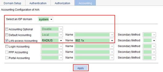
4. Configure wireless service:
a. Select Wireless Service > Access Service from the navigation tree.
b. Click Add.
c. On the page that appears, set the service name to dot1x and select the wireless service type crypto, and click Apply.
Figure 75 Creating a wireless service
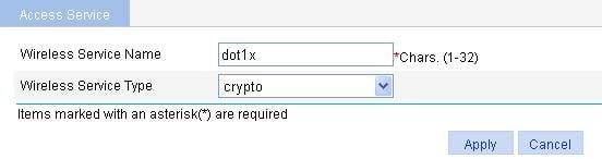
5. Configure 802.1X authentication:
After you create a wireless service, you enter the wireless service configuration page.
a. In the Security Setup area, select the Open-System from the Authentication Type list.
b. Select the Cipher Suite box, select AES from the Cipher Suite list, and select WPA2 from the Security IE list.
c. Select the Port Set box, and select userlogin-secure-ext from the Port Mode list.
d. Select system from the Mandatory Domain list.
e. Select EAP from the Authentication Method list.
f. Disable Handshake and Multicast Trigger (recommended).
g. Click Apply.
Figure 76 Configuring security settings
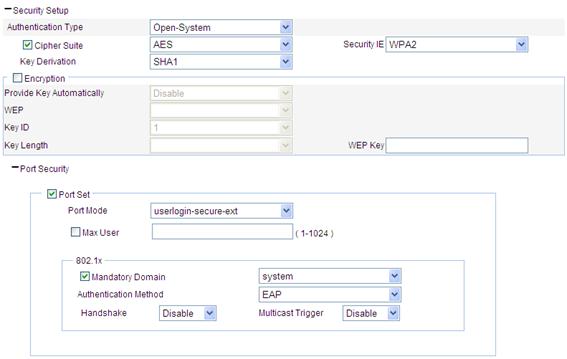
6. Bind an AP radio to a wireless service:
a. Select Wireless Service > Access Service from the navigation tree.
b. Click the ![]() for the wireless service mac-auth to enter the page as shown
in Figure 77.
for the wireless service mac-auth to enter the page as shown
in Figure 77.
c. Select the box with radio mode 802.11n.
d. Click Bind.
Figure 77 Binding an AP radio to a wireless service
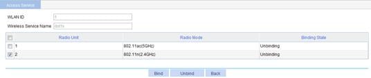
7. Enable the wireless service:
a. Select Wireless Service > Access Service from the navigation tree.
b. On the page that appears, select the dot1x box and click Enable.
Figure 78 Enabling the wireless service
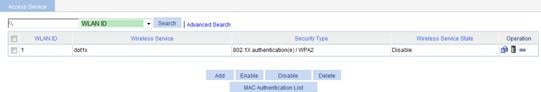
8. Select Radio > Radio from the navigation tree to enter the Radio page.
9. Make sure 802.11n radio is enabled. By default, 802.11n radio is enabled.
Configuring the RADIUS server
For more information about how to configure the RADIUS server, see related IMC guides.
Configuring the wireless card
1.
Double click the ![]() icon at the bottom right corner of your desktop.
icon at the bottom right corner of your desktop.
The Wireless Network Connection Status window appears.
2. Click the Properties button in the General tab.
The Wireless Network Connection Properties window appears.
3. In the Wireless Networks tab, select wireless network with the SSID dot1x, and then click Properties.
The dot1x Properties window appears.
4. In the Authentication tab, select Protected EAP (PEAP) from the EAP type list, and click Properties.
5. In the popup window, clear Validate server certificate, and click Configure.
6. In the popup dialog box, clear Automatically use my Windows logon name and password (and domain if any).
Figure 79 Configuring the wireless card (I)
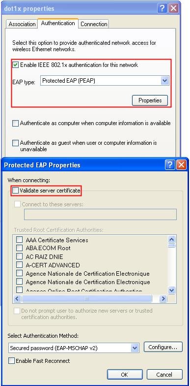
Figure 80 Configuring the wireless card (II)
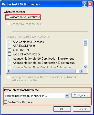
Figure 81 Configuring the wireless card (III)
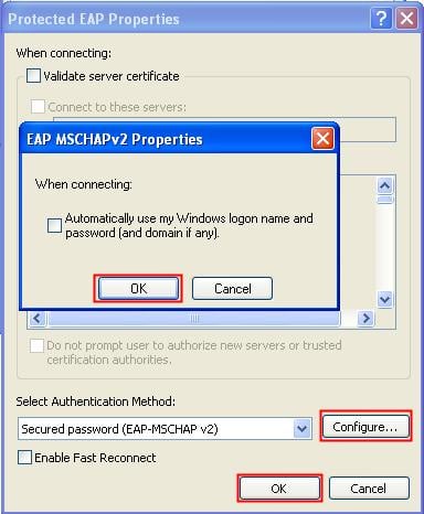
Verifying the configuration
· After entering username user and password dot1x in the popup dialog box, the client can associate with the AP and access the WLAN.
· You can view the online clients on the page that you enter by selecting Summary > Client from the navigation tree.
Dynamic WEP encryption-802.1X authentication configuration example
Network requirements
Perform dynamic WEP encryption-802.1X authentication on the client.
· Use the IMC as a RADIUS server for AAA. On the RADIUS server, configure the client’s username as user, password as dot1x, and shared key as expert. The IP address of the RADIUS server is 10.18.1.88.
· On the AP, configure the shared key as expert, and configure the AP to remove the domain name of a username before sending it to the RADIUS server. The IP address of the AP is 10.18.1.1.
Figure 82 Network diagram
Configuring the AP
1. Assign an IP address to the fat AP:
a. Select Network > VLAN to create a VLAN on the fat AP.
b. Select Device > Interface Management to assign an IP address to the VLAN interface.
2. Configure a RADIUS scheme:
See "Configure a RADIUS scheme."
3. Configure AAA:
See "Configure AAA."
4. Configure a wireless service:
a. Select Wireless Service > Access Service from the navigation tree.
b. Click Add.
c. On the page that appears, enter the service name dot1x and select the wireless service type crypto, and click Apply.
Figure 83 Creating a wireless service
5. Configure 802.1X authentication:
After you create a wireless service, the wireless service configuration page appears.
a. In the Security Setup area, select Open-System from the Authentication Type list.
b. Select Encryption, and select Enable from the Provide Key Automatically list.
c. Select the Cipher Suite box, select CCMP from the Cipher Suite list, and select WPA2 from the Security IE list.
d. Select the Port Set box, and select userlogin-secure-ext from the Port Mode list.
e. Select system from the Mandatory Domain list.
f. Select EAP from the Authentication Method list.
g. Disable Handshake and Multicast Trigger (recommended).
h. Click Apply.
Figure 84 Configuring security settings
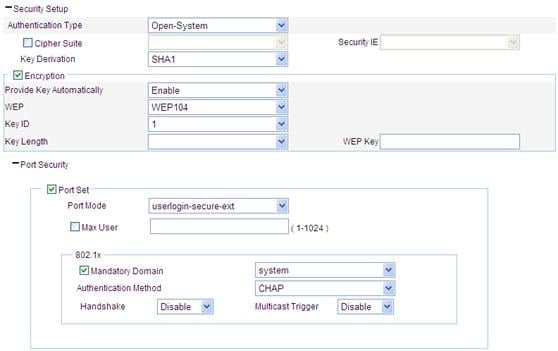
6. Bind an AP radio to a wireless service:
a. Select Wireless Service > Access Service from the navigation tree.
b. Click the ![]() icon for the wireless service dot1x to enter
the page as shown in Figure 85.
icon for the wireless service dot1x to enter
the page as shown in Figure 85.
c. Select the box with radio mode 802.11n.
d. Click Bind.
Figure 85 Binding an AP radio to a wireless service
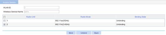
7. Enable the wireless service:
a. Select Wireless Service > Access Service from the navigation tree.
b. Select the dot1x box.
c. Click Enable.
Figure 86 Enabling the wireless service
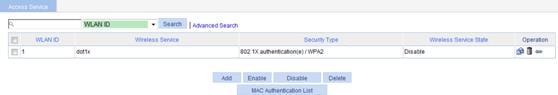
8. Enable 802.11n radio (802.11n radio is enabled by default, so this step is optional).
Select Radio > Radio from the navigation tree to enter the Radio page, and make sure 802.11n is enabled.
Configuring the wireless card
1.
Double click the ![]() icon at the bottom right corner of your desktop. The Wireless Network Connection Status window appears.
icon at the bottom right corner of your desktop. The Wireless Network Connection Status window appears.
2. Click Properties. The Wireless Network window appears.
3. On the Wireless Network window, click Add.
4. Click the Association tab, and enter dot1x in the Network name (SSID) field. Make sure you have selected The key is provided for me automatically.
Figure 87 Configuring the wireless card (I)
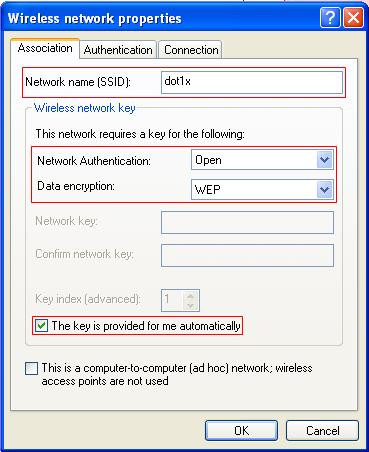
5. On the Authentication tab, select Protected EAP (PEAP) from the EAP type list, and click Properties.
6. In the popup window, clear Validate server certificate, and click Configure.
7. In the popup dialog box, clear Automatically use my Windows logon name and password (and domain if any).
8. Click OK.
Figure 88 Configuring the wireless card (II)
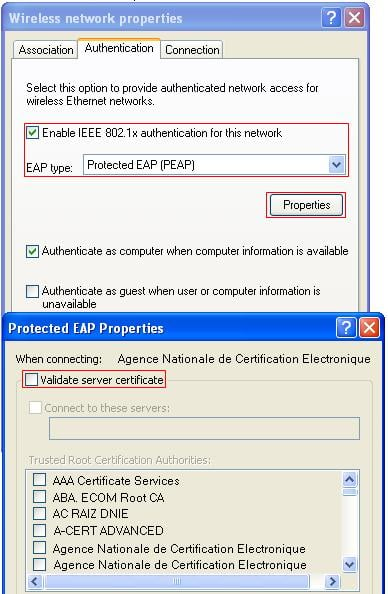
Figure 89 Configuring the wireless card (III)
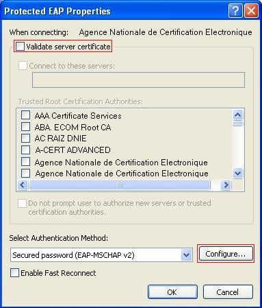
Verifying the configuration
· After the user enters the username user and password dot1x in the popup dialog box, the client can associate with the AP and access the WLAN.
· You can view the online clients on the page that you enter by selecting Summary > Client from the navigation tree.
802.11n configuration example
Network requirements
As shown in Figure 90, deploy an 802.11n network to provide high bandwidth access for multi-media applications. More specifically:
· The AP provides a plain-text wireless service with SSID 11nservice.
· 802.11n (2.4 GHz) is adopted to inter-work with the existing 802.11g network and protect the current investment.
Configuring the AP
1. Assign an IP address to the fat AP:
a. Select Network > VLAN to create a VLAN on the fat AP.
b. Select Device > Interface Management to assign an IP address to the VLAN interface.
2. Configure a wireless service:
a. Select Wireless Service > Access Service from the navigation tree.
b. Click Add.
c. On the page that appears, set the service name to 11nservice, and select the wireless service enter clear, and click Apply.
Figure 91 Creating a wireless service
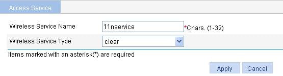
3. Bind an AP radio to a wireless service:
a. Select Wireless Service > Access Service from the navigation tree.
b. Click the ![]() icon for the wireless service 11nservice to
enter the page as shown in Figure
92.
icon for the wireless service 11nservice to
enter the page as shown in Figure
92.
c. Select the box with radio mode 802.11n(2.4GHz).
d. Click Bind.
Figure 92 Binding an AP radio to a wireless service

4. Enable the wireless service:
a. Select Wireless Service > Access Service from the navigation tree.
b. On the page that appears, select the 11nservice box.
c. Click Enable.
Figure 93 Enabling the wireless service
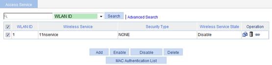
5. Select Radio > Radio from the navigation tree to enter the Radio page.
6. Make sure 802.11n(2.4GHz) is enabled.
Figure 94 Enabling 802.11n(2.4GHz) radio
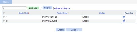
Verifying the configuration
· The client can successfully associate with the AP and access the WLAN network.
· You can view the online clients on the page that you enter by selecting Summary > Client from the navigation tree.
984b-4ad4-3f24 is an 802.11g client, and 984b-4ad4-3fd4 is an 802.11n client. In this example, client types are not restricted. Therefore, both 802.11g and 802.11n clients can access the wireless network. If Client 802.11n Only is configured, only 984b-4ad4-3fd4 can access the wireless network.
Configuration guidelines
When you configure 802.11n, follow these guidelines:
·
Select Radio > Radio from the
navigation tree, select the AP radio unit to be configured, and click the ![]() icon to enter the radio configuration page, where you can modify
the 802.11n-related parameters, including Bandwidth Mode, A-MSDU, A-MPDU, Short GI, and Client 802.11n Only (permitting only 802.11n users to access the wireless network).
icon to enter the radio configuration page, where you can modify
the 802.11n-related parameters, including Bandwidth Mode, A-MSDU, A-MPDU, Short GI, and Client 802.11n Only (permitting only 802.11n users to access the wireless network).
· Make sure 802.11n(2.4GHz) is enabled.
· Select Radio > Rate from the navigation tree to modify the 802.11n rate.
WDS configuration examples
WDS configuration example
Network requirements
In an outdoor environment as shown in Figure 95, connecting the two LAN segments with cables is time-consuming and cost ineffective. Therefore, you can connect the two LAN segments with a WDS link.
· Connect AP 1 and AP 2 to different LAN segments.
· Configure AP 1 and AP 2 to use channel 153 to establish the 802.11ac WDS link.
· Configure pre-shared key 12345678 to ensure WDS link security.
Configuring AP 1
1. Assign an IP address to AP 1:
a. Select Network > VLAN to create a VLAN on AP 1.
b. Select Device > Interface Management to assign an IP address to the VLAN interface.
2. Configure WDS:
a. Select Wireless Service > WDS from the navigation tree to enter the WDS Setup page.
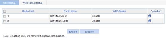
b. Click the ![]() icon for the target radio unit.
icon for the target radio unit.
c. On the page that appears, select the Pass Phrase option, and enter 12345678 in the Preshared Key field, leave the neighbor MAC address field blank (indicating that the AP can establish a WDS link with any other AP), and click Apply.
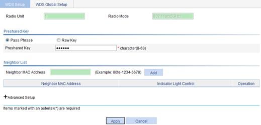
3. Configure the working channel:
a. Select Radio > Radio from the navigation tree.
b. Click the ![]() icon for the target
radio unit to enter the Radio page.
icon for the target
radio unit to enter the Radio page.
c. Select the channel to be used from the Channel list.
d. Click Apply.
Figure 98 Configuring the working channel
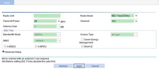
4. Select Radio > Radio from the navigation tree to enter the Radio page.
5. Make sure 802.11ac is enabled.
By default, 802.11ac is enabled.
6. Enable WDS
a. Select Wireless Service > WDS from the navigation tree to enter the WDS Setup page.
b. Select the box corresponding to 802.11ac.
c. Click Enable.
Figure 99 Configuring WDS
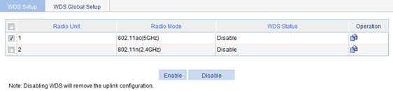
Configuring AP 2
Configure AP 2 in the same way as AP 1 (Details not shown).
Verifying the configuration
Select Summary > WDS from the navigation tree to enter the page displaying WDS information.
Figure 100 The page displaying WDS information
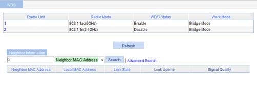
The figure shows that the WDS link has been established.
Configuration guidelines
The output of a WDS link includes: neighbor MAC address, local MAC address, link state, link uptime, and signal quality.
When five green bars are displayed for the signal quality, the signal is of the highest quality. If yellow bars are displayed, the signal is weak. In this case, verify that the antennas in use match the current radio, the antennas are connected correctly, and the maximum power of the current radio is appropriate.
WDS point-to-multipoint configuration example
Network requirements
As shown in Figure 101, establish a WDS link between AP 1 and AP 2, AP 3, and AP 4. The WDS point to multipoint configuration is the same as the normal WLAN WDS configuration.
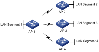
Configuration procedure
WDS point to multipoint configuration is the same as normal WLAN WDS configuration. For more information, see "WDS configuration example."
Verifying the configuration
· Select Summary > WDS from the navigation tree to enter the WDS link status page of AP 1. It shows that AP 1 has established a WDS link with AP 2, AP 3, and AP 4.
· Select Summary > WDS from the navigation tree to enter the WDS link status page of AP 2, AP 3 and AP 4. It shows that AP 2, AP 3, and AP 4 have established a WDS link with AP 1.
Configuration guidelines
Follow these guidelines when you configure WDS:
· Configure a neighbor MAC address for each radio interface. Otherwise, WDS links may be set up between AP 2, AP 3, and AP 4.
· Set the maximum number of WDS links allowed. The default value is 2. It must be set to 3 for AP 1 in this example.
Repeater mode configuration example
Network requirements
As shown in Figure 102, the AP acting as a repeater needs to set up a WDS link with AP 1. At the same time, the repeater needs to provide wireless access service for clients.
· Use the 802.11n radio to set up a WDS link between AP 1 and the repeater.
· Use the 802.11n radio to connect clients to the repeater.
· The access service and WDS link must use the same channel. In this example, channel 11 in 802.11n radio mode is used as the working channel.
· Configure WDS on AP 1. For the detailed configuration procedure, see "Configuring AP 1."
· Configure WDS and access service on the repeater.
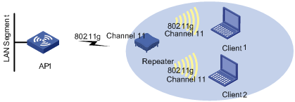
Configuring the repeater
1. Configure WDS:
a. Select Wireless Service > WDS from the navigation tree to enter the WDS Setup page.
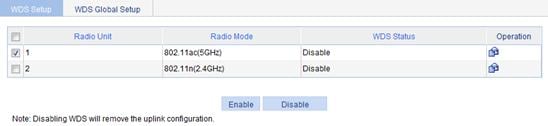
b.
Click the ![]() icon in the Operation column for the target
802.11n radio mode.
icon in the Operation column for the target
802.11n radio mode.
c. Select Pass Phrase and enter 12345678 in the Preshared Key field.
d. Click Apply.
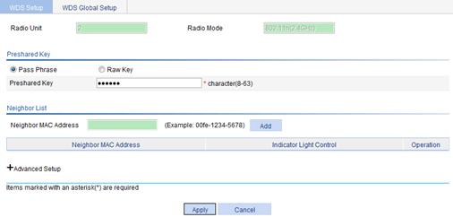
2. Configure the working channel:
a. Select Radio > Radio from the navigation tree.
b. Click the ![]() icon for the target
radio.
icon for the target
radio.
c. On the page that appears, select 4 in the Channel list, and click Apply.
Figure 105 Configuring the same channel
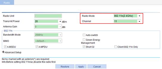
3. Select Radio > Radio from the navigation tree to enter the Radio page.
4. Make sure 802.11n is enabled.
By default, 802.11n is enabled.
5. Enable WDS:
a. Select Wireless Service > WDS from the navigation tree.
b. Select the box corresponding to 802.11n.
c. Click Enable.
6. Configure the access service.
For how to configure the access service on the repeater, see "Wireless service configuration example." You can strictly follow the steps in Wireless service configuration example to configure the access service on the repeater.
Figure 107 Configuring the access service
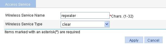
When you configure access service on the repeater, make sure of the following items:
· The access service and WDS link use the same radio mode. In this example, they use the 802.11n mode.
· The access service and WDS link use the same channel. In this example, they use channel 11 in the 802.11n mode.
Verifying the configuration
1. Verify that the WDS link has been established for the repeater:
a. Select Summary > WDS from the navigation tree to enter the WDS page displaying the WDS information.
b. Click radio unit 2 to view the neighbor information.
2. Verify that the repeater mode has been configured successfully:
a. Select Summary > Radio from the navigation tree to enter the page displaying radio information, as shown in Figure 108.
b. On the page, verify that the 802.11n radio mode on the repeater provides both access and WDS services, and one client has accessed the wireless network through the repeater.
Figure 108 The page displaying radio information