- Table of Contents
- Related Documents
-
| Title | Size | Download |
|---|---|---|
| 05-Network | 1.28 MB |
Configuring the MAC address table·
Setting the aging time of MAC address entries
MAC address configuration example
Recommended VLAN configuration procedure
Static ARP entry configuration example
Recommended configuration procedure
Enabling IGMP snooping globally
Configuring IGMP snooping in a VLAN
Configuring IGMP snooping on a port
Displaying IGMP snooping table entries
IGMP snooping configuration example
Configuring IPv4 and IPv6 routing·
Displaying the IPv4 active route table
Displaying the IPv6 active route table
IPv4 static route configuration example
IPv6 static route configuration example
Recommended configuration procedure
Creating a static address pool for the DHCP server
Creating a dynamic address pool for the DHCP server
Enabling the DHCP server on an interface
Displaying the information of assigned IP addresses
DHCP server configuration example
Dynamic domain name resolution
Recommended configuration procedure
Configuring static name resolution table
Configuring dynamic domain name resolution
Configuring static name resolution table
Configuring dynamic domain name resolution
Displaying PPPoE client session statistic information
Displaying PPPoE client session information
PPPoE client configuration example
MAC address configurations related to interfaces apply only to Layer 2 Ethernet interfaces.
This chapter covers only the management of static and dynamic MAC address entries, not multicast MAC address entries.
Overview
An Ethernet device uses a MAC address table for forwarding frames through unicast instead of broadcast. This table describes from which port a MAC address (or host) can be reached. A MAC address table can contain the following types of entries: static and dynamic. Static entries are manually added and never age out. Dynamic entries can be manually added or dynamically learned and will age out.
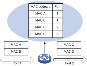
When a frame arrives at a port, Port A for example, the device performs the following tasks:
1. Checks the source MAC address (MAC-SOURCE for example) of the frame.
2. Looks up the source MAC address in the MAC address table.
¡ If an entry is found, the device updates the entry.
¡ If no entry is found, the device adds an entry for the MAC-SOURCE and Port A.
3. After learning this source MAC address, when the device receives a frame destined for MAC-SOURCE, the device finds the MAC-SOURCE entry in the MAC address table and forwards the frame out of Port A.
Dynamically learned MAC addresses cannot overwrite static MAC address entries, but the latter can overwrite the former.
When forwarding a frame, the device adopts the following forwarding modes based on the MAC address table:
· Unicast mode—If an entry is available for the destination MAC address, the device forwards the frame out of the outgoing interface indicates by the MAC address table entry.
· Broadcast mode—If the device receives a frame with an all-ones destination address, or no entry is available for the destination MAC address, the device broadcasts the frame to all the interfaces except the receiving interface.
Figure 1 MAC address table of the device
Configuring MAC addresses
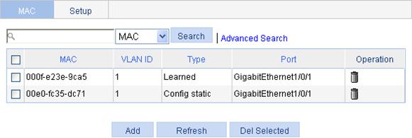
1. Select Network > MAC from the navigation tree.
The system automatically displays the MAC tab, which shows all the MAC address entries on the device.
2. Click Add to enter the page for creating MAC address entries.
Figure 3 Creating a MAC address entry
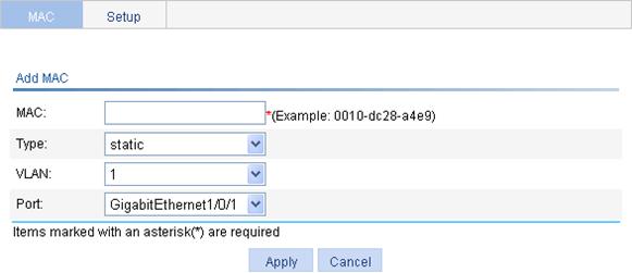
3. Configure the MAC address entry as described in Table 1.
4. Click Apply.
|
Item |
Description |
|
MAC |
Set the MAC address to be added. |
|
Type |
Set the type of the MAC address entry: · Static—Static MAC address entries that never age out. · Dynamic—Dynamic MAC address entries that will age out. · Blackhole—Blackhole MAC address entries that never age out. The tab displays the following types of MAC address entries: · Config static—Static MAC address entries manually configured by the users. · Config dynamic—Dynamic MAC address entries manually configured by the users. · Blackhole—Blackhole MAC address entries. · Learned—Dynamic MAC address entries learned by the device. · Other—Other types of MAC address entries. |
|
VLAN |
Set the ID of the VLAN to which the MAC address belongs. |
|
Port |
Set the port to which the MAC address belongs. |
Setting the aging time of MAC address entries
1. Select Network > MAC from the navigation tree.
2. Click the Setup tab to enter the page for setting the MAC address entry aging time.
Figure 4 Setting the aging time for MAC address entries
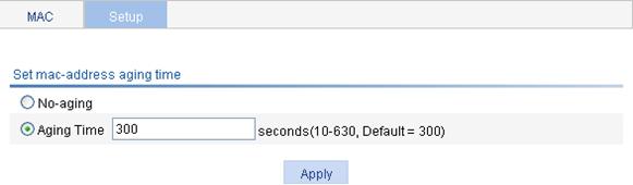
3. Set the aging time as described in Table 2.
4. Click Apply.
|
Item |
Description |
|
No-aging |
Specify that the MAC address entry never ages out. |
|
Aging time |
Set the aging time for the MAC address entry. |
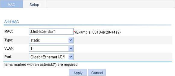
MAC address configuration example
Network requirements
Use the MAC address table management function of the Web-based NMS. Create a static MAC address 00e0-fc35-dc71 for GigabitEthernet 1/0/1 in VLAN 1.
Configuration procedure
1. Select Network > MAC from the navigation tree to enter the MAC tab.
2. Click Add.
3. Enter the MAC address 00e0-fc35-dc71. Select static from the Type list. Select 1 from the VLAN list. Select GigabitEthernet1/0/1 from the Port list.
4. Click Apply.
Figure 5 Creating a static MAC address entry
Overview
Ethernet is a network technology based on the CSMA/CD mechanism. As the medium is shared, collisions and excessive broadcasts are common on an Ethernet. To address the issue, virtual LAN (VLAN) was introduced to break a LAN down into separate VLANs. VLANs are isolated from each other at Layer 2. A VLAN is a bridging domain, and all broadcast traffic is contained within it, as shown in Figure 6.
You can implement VLANs based on a variety of criteria. However, the Web interface is available only for port-based VLANs, which group VLAN members by port. A port forwards traffic for a VLAN only after it is assigned to the VLAN.
For more information about the VLAN feature, see Layer 2 Configuration Guide.
Recommended VLAN configuration procedure
|
Step |
Remarks |
|
Required. |
|
|
Select at least one task. Configure the untagged member ports and tagged member ports of the VLAN, or remove ports from the VLAN. |
|
Creating a VLAN
1. Select Network > VLAN from the navigation tree.
The system automatically selects the VLAN tab.
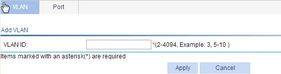
Figure 7 VLAN configuration page
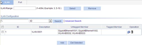
To easily configure a specific range of VLANs within a large number of VLANs, enter a VLAN range in the VLAN Range field and click Select, and all undesired VLANs will be filtered out. If you click Remove, all VLANs within this range will be deleted.
2. Click Add.
3. Enter the ID of the VLAN you want to create.
4. Click Apply.
Modifying a VLAN
1. Select Network > VLAN from the navigation tree.
The system automatically selects the VLAN tab.
2.
Click the ![]() icon for the VLAN
you want to modify.
icon for the VLAN
you want to modify.
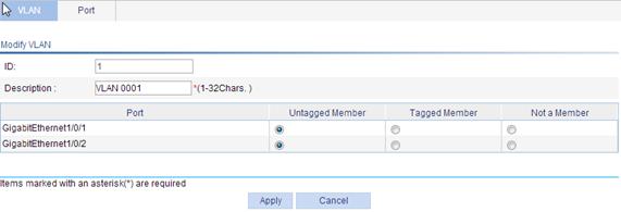
3. Configure the description and port members for the VLAN as described in Table 3.
4. Click Apply.
|
Item |
Description |
|
ID |
Display the ID of the VLAN to be modified. |
|
Description |
Set the description string of the VLAN. By default, the description string of a VLAN is its VLAN ID, such as VLAN 0001. |
|
Port |
Set the member type for the port to be modified in the VLAN: · Untagged Member—Configure the port to send the traffic of the VLAN after removing the VLAN tag. · Tagged Member—Configure the port to send the traffic of the VLAN without removing the VLAN tag. · Not a Member—Remove the port from the VLAN. When you configure an access port as a tagged member of a VLAN, the link type of the port is automatically changed into hybrid. |
Modifying a port
1. Select Network > VLAN from the navigation tree.
2. Click the Port tab.
Figure 10 Port configuration page
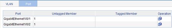
3.
Click the ![]() icon for the port to be modified.
icon for the port to be modified.
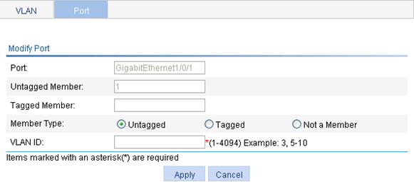
4. Configure the port members for the VLAN as described in Table 4.
5. Click Apply.
|
Item |
Description |
|
Port |
Display the port to be modified. |
|
Untagged Member |
Display the VLANs to which the port belongs as an untagged member. |
|
Tagged Member |
Display the VLANs to which the port belongs as a tagged member. |
|
Member Type |
Set the target member type for the port: · Untagged—Configure the port to send the traffic of the VLAN after removing the VLAN tag. · Tagged—Configure the port to send the traffic of the VLAN without removing the VLAN tag. · Not a Member—Remove the port from the VLAN. When you configure the member type, follow these guidelines: · You cannot configure an access port as an untagged member of a nonexistent VLAN. · When you configure an access port as a tagged member of a VLAN, or configure a trunk port as an untagged member of multiple VLANs in bulk, the link type of the port is automatically changed into hybrid. · You can configure a hybrid port as a tagged or untagged member of a VLAN only if the VLAN is an existing, static VLAN. |
|
VLAN ID |
Specify the VLAN to which the port belongs. |
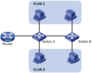
VLAN configuration example
Network requirements
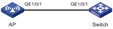
As shown in Figure 12:
· GigabitEthernet 1/0/1 of AP is connected to GigabitEthernet 1/0/1 of Switch.
· GigabitEthernet 1/0/1 on both devices are hybrid ports with VLAN 1 as the PVID.
Configure GigabitEthernet 1/0/1 to allow packets of VLAN 1, VLAN 2, VLAN 6 through VLAN 50, and VLAN 100 to pass through and allow packets of VLAN 1 and VLAN 100 to pass through untagged.
Configuring the AP
By default, GigabitEthernet 1/0/1 is an access port whose PVID is 1.
In this configuration example, GigabitEthernet 1/0/1 is first configured as a tagged member of VLAN 2 and VLANs 6 through 50 and then as an untagged member of VLAN 100. If you reverse the configuration order, you must enter 1 and 100 in the VLAN ID field when you configure GigabitEthernet 1/0/1 as an untagged member of VLANs. Otherwise, the PVID of the port will change to 100.
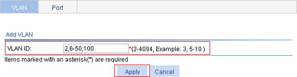
1. Create VLAN 2, VLAN 6 through VLAN 50, and VLAN 100:
a. Select Network > VLAN from the navigation tree to enter the VLAN tab.
b. Click Add.
c. Enter VLAN IDs 2,6-50,200.
d. Click Apply.
2. Configure GigabitEthernet 1/0/1 as a tagged member of VLAN 2 and VLANs 6 through 50:
a. Click the Port tab.
b. Click the ![]() icon
for GigabitEthernet 1/0/1.
icon
for GigabitEthernet 1/0/1.
c. Select the Tagged option.
d. Enter VLAN IDs 2,6-50.
Figure 14 Configuring GigabitEthernet 1/0/1 as a tagged member of VLAN 2 and VLANs 6 through 50
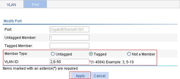
e. Click Apply.
A dialog box appears asking you to confirm the operation.
f. Click OK in the dialog box.
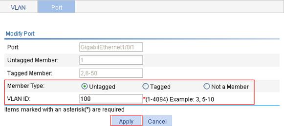
3. Configure GigabitEthernet 1/0/1 as an untagged member of VLAN 100:
a. Click the ![]() icon for
GigabitEthernet 1/0/1 on the port list.
icon for
GigabitEthernet 1/0/1 on the port list.
b. Select the Untagged option.
c. Enter VLAN ID 100.
d. Click Apply.
Figure 15 Configuring GigabitEthernet 1/0/1 as an untagged member of VLAN 100
Configuring the switch
Configure the switch as you configured the AP.
Configuration guidelines
Follow these guidelines when you configure VLAN:
· As the default VLAN, VLAN 1 cannot be manually created or removed.
· You cannot manually create or remove VLANs reserved for special purposes.
· Dynamic VLANs cannot be manually removed.
Overview
The Address Resolution Protocol (ARP) is used to resolve an IP address into a physical address such as an Ethernet MAC address.
In an Ethernet LAN, a device uses ARP to get the MAC address of the target device for a packet.
For more information about ARP, see Layer 3 Configuration Guide.
Gratuitous ARP
Gratuitous ARP packets
In a gratuitous ARP packet, the sender IP address and the target IP address are the IP address of the sending device, the sender MAC address is the MAC address of the sending device, and the target MAC address is the broadcast address ff:ff:ff:ff:ff:ff.
A device sends a gratuitous ARP packet for either of the following purposes:
· Determine whether its IP address is already used by another device. If the IP address is already used, the device is informed of the conflict by an ARP reply.
· Inform other devices of the change of its MAC address.
Enabling learning of gratuitous ARP packets
With this feature enabled, a device, upon receiving a gratuitous ARP packet, adds an ARP entry that contains the sender IP and MAC addresses in the packet to its ARP table. If the corresponding ARP entry exists, the device updates the ARP entry.
With this feature disabled, the device uses the received gratuitous ARP packets to update existing ARP entries, but not to create new ARP entries.
Displaying ARP entries
From the navigation tree, select Network > ARP Management to enter the default ARP Table page shown in Figure 16. All ARP entries are displayed on the page.
Figure 16 ARP Table configuration page

Creating a static ARP entry
1. From the navigation tree, select Network > ARP Management to enter the default ARP Table page shown in Figure 16.
2. Click Add to enter the New Static ARP Entry page.
Figure 17 Add a static ARP entry
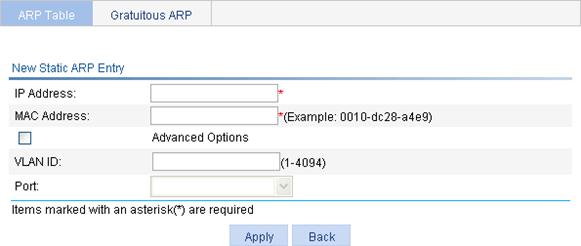
3. Configure the static ARP entry as described in Table 5.
4. Click Apply.
|
Item |
Description |
|
|
IP Address |
Enter an IP address for the static ARP entry. |
|
|
MAC Address |
Enter a MAC address for the static ARP entry. |
|
|
Advanced Options |
VLAN ID |
Enter a VLAN ID and specify a port for the static ARP entry.
The VLAN ID must be the ID of the VLAN that has already been created, and the port must belong to the VLAN. The corresponding VLAN interface must have been created. |
|
Port |
||
Removing ARP entries
1. From the navigation tree, select Network > ARP Management to enter the default ARP Table page shown in Figure 16.
2. Remove ARP entries:
¡ To remove specific ARP entries, select the boxes of target ARP entries, and click Del Selected.
¡ To remove all static and dynamic ARP entries, click Delete Static and Dynamic.
¡ To remove all static ARP entries, click Delete Static.
¡ To remove all dynamic ARP entries, click Delete Dynamic.
Configuring gratuitous ARP
1. From the navigation tree, select Network > ARP Management.
2. Click the Gratuitous ARP tab.
Figure 18 Gratuitous ARP configuration page
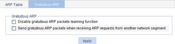
3. Configure gratuitous ARP as described in Table 6.
4. Click Apply.
|
Item |
Description |
|
Disable gratuitous ARP packets learning function |
Disable learning of ARP entries according to gratuitous ARP packets. Enabled by default. |
|
Send gratuitous ARP packets when receiving ARP requests from another network segment |
Enable the device to send gratuitous ARP packets upon receiving ARP requests from another network segment. Disabled by default. |
Static ARP entry configuration example
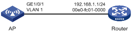
Network requirements
As shown in Figure 19, configure static ARP entries for the AP to communicate with the router.
Creating a static ARP entry
Before performing the following configuration, configure interface VLAN-interface 1 and log in to the web configuration page of the AP through VLAN-interface 1.
1. From the navigation tree, select Network > ARP Management to enter the default ARP Table page.
2. Click Add.
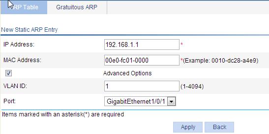
The page for adding a static ARP entry appears, as shown in Figure 20.
3. Enter 192.168.1.1 for IP Address.
4. Enter 00e0-fc01-0000 for MAC Address.
5. Select the Advanced Options box.
6. Enter 1 for VLAN ID.
7. Select GigabitEthernet1/0/1 for Port.
8. Click Apply.
Figure 20 Creating a static ARP entry
Overview
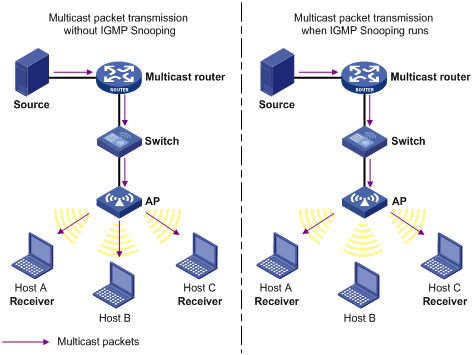
Internet Group Management Protocol (IGMP) snooping is a multicast constraining mechanism that runs on Layer 2 devices to manage and control multicast groups.
By analyzing received IGMP messages, a Layer 2 device that is running IGMP snooping establishes mappings between ports and multicast MAC addresses and forwards multicast data based on these mappings.
As shown in Figure 21, without IGMP snooping, a Layer 2 switch floods multicast packets out of all ports but the incoming port. IGMP snooping enables a Layer 2 switch to forward multicast packets destined for a known multicast group address out of only ports that have multicast receivers. This feature improves bandwidth efficiency, enhances multicast security, and helps per-host accounting for multicast users.
For more information about IGMP snooping, see IP Multicast Configuration Guide.
Figure 21 Multicast forwarding before and after IGMP snooping runs
Recommended configuration procedure
|
Step |
Remarks |
|
Required. Disabled by default. |
|
|
Required. Enable IGMP snooping in the VLAN and configure the IGMP snooping version and querier feature. By default, IGMP snooping is disabled in a VLAN.
· You must enable IGMP snooping globally before enabling it in a VLAN. · After enabling IGMP snooping in a VLAN, do not enable IGMP or PIM on the corresponding VLAN interface, and vice versa. · When you enable IGMP snooping in a VLAN, this function takes effect only on the ports in this VLAN. |
|
|
Optional. Configure the maximum number of multicast groups allowed and the fast-leave function for ports in the specified VLAN.
· You must enable multicast routing or IGMP snooping globally before enabling IGMP snooping on a port. · IGMP snooping configured on a port takes effect only after IGMP snooping is enabled in the VLAN or IGMP is enabled in the VLAN interface. |
|
|
Optional. |
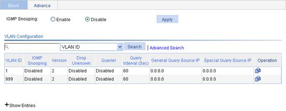
Enabling IGMP snooping globally
1. From the navigation tree, select Network > IGMP snooping.
2. Select Enable.
3. Click Apply.
Figure 22 Basic IGMP snooping configurations
Configuring IGMP snooping in a VLAN
1. From the navigation tree, select Network > IGMP snooping.
2.
Click the ![]() icon
corresponding to the VLAN.
icon
corresponding to the VLAN.
Figure 23 Configuring IGMP snooping in the VLAN
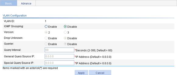
3. Configure the parameters as described in Table 7.
4. Click Apply.
|
Item |
Description |
|
VLAN ID |
This field displays the ID of the VLAN to be configured. |
|
IGMP snooping |
Enable or disable IGMP snooping in the VLAN. You can proceed with the subsequent configurations only if you select Enable. |
|
Version |
By configuring the version of IGMP snooping, you actually configure the versions of IGMP messages that IGMP snooping can process. · IGMPv2 snooping can process IGMPv1 and IGMPv2 messages, but cannot process IGMPv3 messages, which will be flooded in the VLAN. · IGMPv3 snooping can process IGMPv1, IGMPv2 and IGMPv3 messages.
If you change IGMPv3 snooping to IGMPv2 snooping, the system clears all IGMP snooping forwarding entries that are dynamically added. |
|
Drop Unknown |
Enable or disable the function of dropping unknown multicast packets. Unknown multicast data refers to multicast data for which no entries exist in the IGMP snooping forwarding table. · With the function of dropping unknown multicast data enabled, the device drops all the unknown multicast data received. · With the function of dropping unknown multicast data disabled, the device floods unknown multicast data in the VLAN to which the unknown multicast data belong. |
|
Querier |
Enable or disable the IGMP snooping querier function. On an IP multicast network that runs IGMP, a Layer 3 device acts as an IGMP querier to send IGMP queries and establish and maintain multicast forwarding entries for correct multicast traffic forwarding at the network layer. On a network without Layer 3 multicast devices, no IGMP querier-related function can be implemented because a Layer 2 device does not support IGMP. To address this issue, you can enable IGMP snooping querier on a Layer 2 device so that the device can generate and maintain multicast forwarding entries at data link layer, thereby implementing IGMP querier-related functions. |
|
Query interval |
Configure the IGMP query interval. |
|
General Query Source IP |
Source IP address of IGMP general queries. |
|
Special Query Source IP |
Source IP address of IGMP group-specific queries. |
Configuring IGMP snooping on a port
1. From the navigation tree, select Network > IGMP snooping.
2. Click the Advanced tab.
Figure 24 Advanced configuration
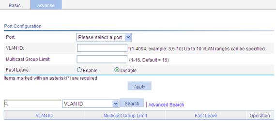
3. Configure the parameters as described in Table 8.
4. Click Apply.
|
Item |
Description |
|
Port |
Select the port on which advanced IGMP snooping features will be configured. After a port is selected, advanced features configured on this port are displayed at the lower part of this page. |
|
VLAN ID |
Specify a VLAN in which you can configure the fast-leave function for the port or the maximum number of multicast groups allowed on the port. |
|
Group Limit |
Configure the maximum number of multicast groups that the port can join. With this feature, you can regulate multicast traffic on the port.
When the number of multicast groups a port has joined reaches the configured threshold, the system deletes all the forwarding entries persistent on that port from the IGMP snooping forwarding table, and the hosts on this port must join the multicast groups again. |
|
Fast Leave |
Enable or disable the fast-leave function for the port. With the fast-leave function enabled on a port, the device, when receiving an IGMP leave message on the port, immediately deletes that port from the outgoing port list of the corresponding forwarding table entry. Then, when receiving IGMP group-specific queries for that multicast group, the device will not forward them to that port.
You can enable IGMP snooping fast-leave processing on a port that has only one receiver host attached to save bandwidth and resources. If a port has multiple hosts attached and the function of dropping unknown multicast packets has been enabled on the switch or in the VLAN where the port resides, you should not enable IGMP snooping fast-leave processing on this port because other hosts attached to this port in the same multicast group cannot receive the multicast data for the group. |
Displaying IGMP snooping table entries
1. From the navigation tree, select Network > IGMP snooping.
2. Click Show Entries to display information about IGMP snooping table entries.
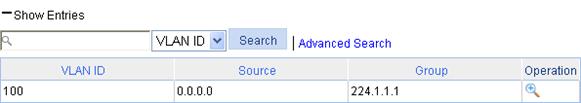
Figure 25 Displaying entry information
3.
Click the ![]() icon corresponding to the entry to view detailed information about
an entry.
icon corresponding to the entry to view detailed information about
an entry.
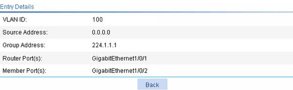
Figure 26 Detailed information of an entry
|
Field |
Description |
|
VLAN ID |
ID of the VLAN to which the entry belongs. |
|
Source |
Multicast source address, where 0.0.0.0 indicates all multicast sources. |
|
Group |
Multicast group address. |
|
Router port |
All router ports. |
|
Member port |
All member ports. |
IGMP snooping configuration example
Network requirements
IGMPv2 runs on Router A and IGMPv2 snooping runs on the AP. Router A acts as the IGMP querier.
Perform the configuration so Host A can receive the multicast data addressed to the multicast group 224.1.1.1, and AP drops unknown multicast data instead of flooding it in the VLAN.
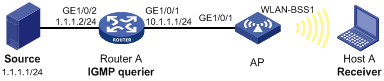
Configuring Router A
Enable IP multicast routing, enable PIM-DM on each interface, and enable IGMP on GigabitEthernet 1/0/1. (Details not shown.)
Configuring the AP
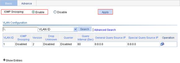
1. Enable IGMP snooping globally:
a. From the navigation tree, select Network > IGMP snooping.
b. Select the Enable option for IGMP snooping.
c. Click Apply.
Figure 28 Enabling IGMP snooping globally
2. On VLAN 1, where GigabitEthernet 1/0/1 and WLAN-BSS 1 reside, enable IGMP snooping and the function of dropping unknown multicast data:
a.
Click the ![]() icon corresponding
to VLAN 1.
icon corresponding
to VLAN 1.
b. Select the Enable option for IGMP snooping.
c. Select the 2 option for Version.
d. Select the Enable option for Drop Unknown.
e. Click Apply to complete the operation.
Figure 29 Configuring the VLAN

Verifying the configuration
To display the IGMP snooping multicast entry information on the AP:
1. From the navigation tree, select Network > IGMP snooping.
2. Click Show Entries in the basic VLAN configuration page to display information about IGMP snooping multicast entries.
Figure 30 IGMP snooping multicast entry information displaying page
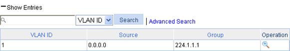
3.
Click the ![]() icon corresponding to the multicast entry to view information about this entry. The page shows
that WLAN-BSS 1 of the AP is added to multicast group 224.1.1.1.
icon corresponding to the multicast entry to view information about this entry. The page shows
that WLAN-BSS 1 of the AP is added to multicast group 224.1.1.1.
The term "router" in this chapter refers to both routers and Layer 3 switches.
Overview
Upon receiving a packet, a router determines the optimal route based on the destination address and forwards the packet to the next router in the path. When the packet reaches the last router, it then forwards the packet to the destination host. Routing provides the path information that guides the forwarding of packets.
A router selects optimal routes from the routing table, and sends them to the forwarding information base (FIB) table to guide packet forwarding. Each router maintains a routing table and a FIB table.
Static routes are manually configured. If a network’s topology is simple, you only need to configure static routes for the network to work properly. Static routes cannot adapt to network topology changes. If a fault or a topological change occurs in the network, the network administrator must modify the static routes manually.
For more information about routing table and static routing, see Layer 3 Configuration Guide.
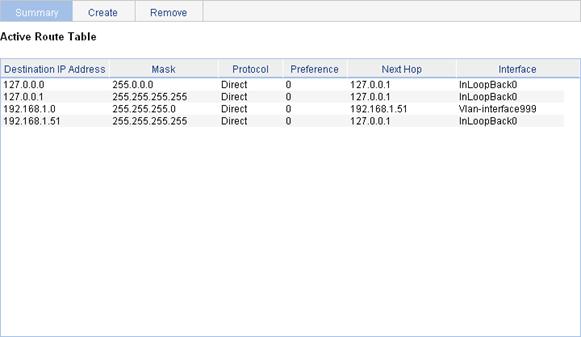
Displaying the IPv4 active route table
Select Network > IPv4 Routing from the navigation tree to enter the page in Figure 31.
Figure 31 IPv4 active route table
|
Field |
Description |
|
Destination IP Address |
Destination IP address and subnet mask of the IPv4 route.. |
|
Mask |
|
|
Protocol |
Protocol that discovered the IPv4 route. |
|
Preference |
Preference value for the IPv4 route. The smaller the number, the higher the preference. |
|
Next Hop |
Next hop IP address of the IPv4 route. |
|
Interface |
Outgoing interface of the IPv4 route. Packets destined for the specified network segment are sent out of the interface. |
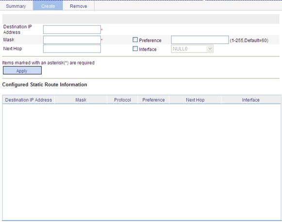
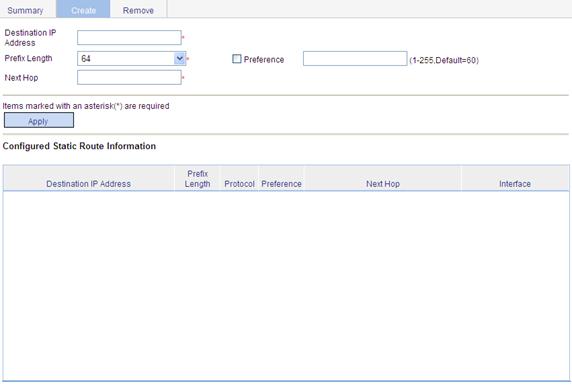
Creating an IPv4 static route
1. Select Network > IPv4 Routing from the navigation tree.
2. Click the Create tab.
The page for configuring IPv4 static route appears.
Figure 32 Creating an IPv4 static route
3. Specify relevant information as described in Table 11.
4. Click Apply.
|
Item |
Description |
|
Destination IP Address |
Enter the destination host or network IP address, in dotted decimal notation. |
|
Mask |
Enter the mask of the destination IP address. You can enter a mask length or a mask in dotted decimal notation. |
|
Preference |
Set a preference value for the static route. The smaller the number, the higher the preference. For example, specifying the same preference for multiple static routes to the same destination enables load sharing on the routes, while specifying different preferences enables route backup. |
|
Next Hop |
Enter the next hop IP address, in dotted decimal notation. |
|
Interface |
Select the outgoing interface. You can select any available Layer 3 interface, for example, a virtual interface, of the device. If you select NULL 0, the destination IP address is unreachable. |
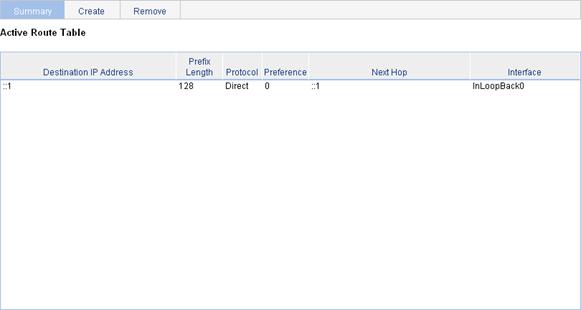
Displaying the IPv6 active route table
Select Network > IPv6 Routing from the navigation tree to enter the page in Figure 33.
Figure 33 IPv6 active route table
|
Field |
Description |
|
Destination IP Address |
Destination IP address and prefix length of the IPv6 route.. |
|
Prefix Length |
|
|
Protocol |
Protocol that discovered the IPv6 route. |
|
Preference |
Preference value for the IPv6 route. The smaller the number, the higher the preference. |
|
Next Hop |
Next hop IP address of the IPv6 route. |
|
Interface |
Outgoing interface of the IPv6 route. Packets destined for the specified network segment are sent out of the interface. |
Creating an IPv6 static route
1. Select Network > IPv6 Routing from the navigation tree.
2. Click the Create tab.
The page for configuring IPv6 static route appears.
Figure 34 Creating an IPv6 static route
3. Specify relevant information as described in Table 13.
4. Click Apply.
|
Item |
Description |
|
Destination IP Address |
Enter the destination host or network IP address, in the X:X::X:X format. The 128-bit destination IPv6 address is a hexadecimal address with eight parts separated by colons (:). Each part is represented by a 4-digit hexadecimal integer. |
|
Prefix Length |
Enter the prefix length of the destination IPv6 address. |
|
Preference |
Set a preference value for the static route. The smaller the number, the higher the preference. For example, specifying the same preference for multiple static routes to the same destination enables load sharing on the routes, while specifying different priorities for them enables route backup. |
|
Next Hop |
Enter the next hop address, in the same format as the destination IP address. |
|
Interface |
Select the outgoing interface. You can select any available Layer 3 interface, for example, a virtual interface, of the device. If you select NULL 0, the destination IPv6 address is unreachable. |
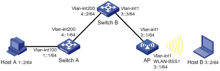
IPv4 static route configuration example
Network requirements
The IP addresses of devices are shown in Figure 35. IPv4 static routes must be configured on Switch A, Switch B and AP for Host A and Host B to communicate with each other.

Configuration considerations
1. On Switch A, configure a default route to Switch B.
2. On Switch B, configure a static route to Switch A.
3. On AP, configure a default route with Switch B.
Configuration procedure
1. Specify gateway 1.1.2.3 for Host A and gateway 1.1.3.3 for Host B.
2. Configure a default route with the next hop address 1.1.4.2 on Switch A.
3. Configure a static route with destination address 1.1.2.0/24 and next hop address 1.1.4.1 on Switch B.
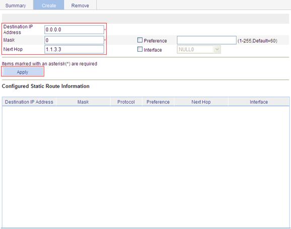
4. Configure a default route on AP:
a. Log in to the Web interface of AP, and select Network > IPv4 Routing from the navigation tree.
b. Click the Create tab to enter the IPv4 static route configuration page.
c. Enter 0.0.0.0 for Destination IP Address, enter 0 for Mask, and enter 1.1.3.3 for Next Hop.
d. Click Apply.
Figure 36 Configuring a default route
Verifying the configuration
1. Display the route table:
Enter the IPv4 route page of Switch A, Switch B, and AP to verify that the newly configured static routes are displayed as active routes on the pages.
2. Ping Host B from Host A (assuming both hosts run Windows XP):
C:\Documents and Settings\Administrator>ping 1.1.3.2
Pinging 1.1.3.2 with 32 bytes of data:
Reply from 1.1.3.2: bytes=32 time=1ms TTL=128
Reply from 1.1.3.2: bytes=32 time=1ms TTL=128
Reply from 1.1.3.2: bytes=32 time=1ms TTL=128
Reply from 1.1.3.2: bytes=32 time=1ms TTL=128
Ping statistics for 1.1.3.2:
Packets: Sent = 4, Received = 4, Lost = 0 (0% loss),
Approximate round trip times in milli-seconds:
Minimum = 1ms, Maximum = 1ms, Average = 1ms
IPv6 static route configuration example
Network requirements
The IP addresses of devices are shown in Figure 37. IPv6 static routes must be configured on Switch A, Switch B and AP for Host A and Host B to communicate with each other.
Configuration considerations
1. On Switch A, configure a default route to Switch B.
2. On Switch B, configure a static route to Switch A.
3. On AP, configure a default route to Switch B.
Configuration procedure
1. Specify gateway 1::1 for Host A and gateway 3::1 for Host B.
2. Configure a default route with the next hop address 4::2 on Switch A.
3. Configure a static route with destination address 1::/64 and next hop address 4::1 on Switch B.
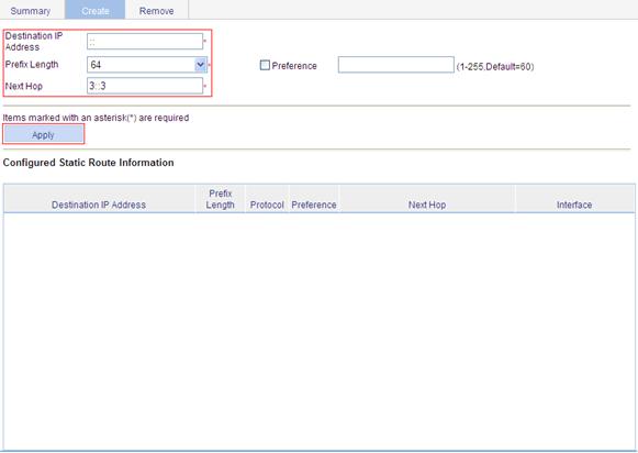
4. Configure a default route on AP:
a. Log in to the Web interface of AP, and select Network > IPv6 Routing from the navigation tree.
b. Click the Create tab to enter the IPv6 static route configuration page.
c. Enter :: for Destination IP Address, select 0 for Prefix Length, and enter 3::3 for Next Hop.
d. Click Apply.
Figure 38 Configuring a default route
Verifying the configuration
1. Display the route table:
Enter the IPv6 route page of Switch A, Switch B, and AP to verify that the newly configured static routes are displayed as active routes on the pages.
2. Ping Host B from Switch A:
<SwitchA> system-view
[SwitchA] ping ipv6 3::2
PING 3::2 : 56 data bytes, press CTRL_C to break
Reply from 3::2
bytes=56 Sequence=1 hop limit=254 time = 63 ms
Reply from 3::2
bytes=56 Sequence=2 hop limit=254 time = 62 ms
Reply from 3::2
bytes=56 Sequence=3 hop limit=254 time = 62 ms
Reply from 3::2
bytes=56 Sequence=4 hop limit=254 time = 63 ms
Reply from 3::2
bytes=56 Sequence=5 hop limit=254 time = 63 ms
--- 3::2 ping statistics ---
5 packet(s) transmitted
5 packet(s) received
0.00% packet loss
round-trip min/avg/max = 62/62/63 ms
Configuration guidelines
When you configure a static route, follow these guidelines:
· If you do not specify the preference, the default preference is used. Reconfiguration of the default preference applies only to newly created static routes. The Web interface does not support configuration of the default preference.
· If you specify the next hop address first and then configure it as the IP address of a local interface, such as an Ethernet interface and VLAN interface, the static route does not take effect.
· When you specify the output interface, note the following:
¡ If NULL 0 or a loopback interface is specified as the output interface, there is no need to configure the next hop address.
¡ If a point-to-point interface is specified as the output interface, you do not need to specify the next hop or change the configuration after the peer address has changed. For example, a PPP interface obtains the peer’s IP address through PPP negotiation, and therefore, you only need to specify it as the output interface.
DHCP overview
After the DHCP client is enabled on an interface, the interface can dynamically obtain an IP address and other configuration parameters from the DHCP server. This facilitates configuration and centralized management. For more information about the DHCP client configuration, see "Managing interfaces."
For more information about DHCP, see Layer 3 Configuration Guide.
Introduction to DHCP
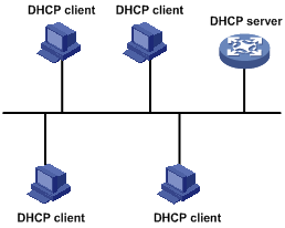
The Dynamic Host Configuration Protocol (DHCP) provides a framework to assign configuration information to network devices.
DHCP uses the client/server model.
Figure 39 A typical DHCP application
Configuring DHCP server
Recommended configuration procedure
|
Task |
Remarks |
|
Required. Enable DHCP globally. By default, global DHCP is disabled. |
|
|
Required to configure either of the two.
If the DHCP server and DHCP clients are on the same subnet, make sure the address pool is on the same network segment as the interface with the DHCP server enabled. Otherwise, the clients fail to obtain IP addresses. |
|
|
Optional. With the DHCP server enabled on an interface, upon receiving a client's request, the DHCP server assigns an IP address from its address pool to the DHCP client. With DHCP enabled, interfaces operate in the DHCP server mode.
The DHCP server works on interfaces with IP addresses manually configured only. |
|
|
Optional. |
Enabling DHCP
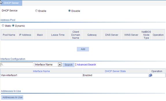
1. From the navigation tree, select Network > DHCP to enter the default DHCP Server page shown in Figure 40.
2. Select the Enable option on the upper part of the page to enable DHCP globally.
Figure 40 DHCP configuration page
Creating a static address pool for the DHCP server
1. From the navigation tree, select Network > DHCP to enter the default DHCP Server page shown in Figure 40.
2. Select the Static option in the Address Pool field to view all static address pools.
3. Click Add.
Figure 41 Creating a static address pool
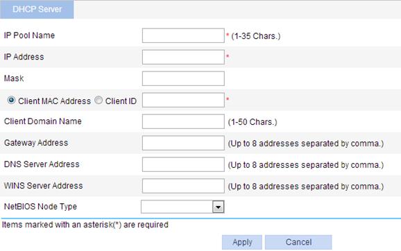
4. Configure the address pool as described in Table 5.
5. Click Apply.
Table 14 Configuration items
|
Item |
Description |
|
IP Pool Name |
Enter the name of a static address pool. |
|
IP Address |
Enter an IP address and select a subnet mask for the static address pool. The IP address cannot be the IP address of any interface on the DHCP server. Otherwise, an IP address conflict may occur and the bound client cannot obtain an IP address correctly. You can enter a mask length or a mask in dotted decimal notation. |
|
Mask |
|
|
Client MAC Address |
Configure the client MAC address or the client ID for the static address pool.
The client ID must be identical to the ID of the client to be bound. Otherwise, the client cannot obtain an IP address. |
|
Client ID |
|
|
Client Domain Name |
Enter the domain name suffix for the client. With the suffix assigned, the client only needs to input part of a domain name, and the system adds the domain name suffix for name resolution. |
|
Gateway Address |
Enter the gateway addresses for the client. A DHCP client that wants to access an external host needs to send requests to a gateway. You can specify gateways in each address pool and the DHCP server assigns gateway addresses while assigning an IP address to the client. Up to eight gateways can be specified in a DHCP address pool, separated by commas. |
|
DNS Server Address |
Enter the DNS server addresses for the client. To allow the client to access a host on the Internet through DNS, you need to specify a DNS server address. Up to eight DNS servers can be specified in a DHCP address pool, separated by commas. |
|
WINS Server Address |
Enter the WINS server addresses for the client. If b-node is specified for the client, you do not need to specify any WINS server address. Up to eight WINS servers can be specified in a DHCP address pool, separated by commas. |
|
NetBIOS Node Type |
Select the NetBIOS node type for the client. |
Creating a dynamic address pool for the DHCP server
1. From the navigation tree, select Network > DHCP to enter the default DHCP Server page shown in Figure 40.
2. Select the Dynamic option in the Address Pool area to view all dynamic address pools.
3. Click Add.
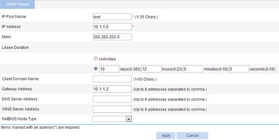
Figure 42 Create a dynamic address pool
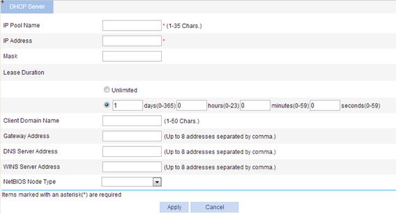
4. Configure the dynamic address pool as described in Table 15.
5. Click Apply.
|
Item |
Description |
|
|
IP Pool Name |
Enter the name of a dynamic address pool. |
|
|
IP Address |
Enter an IP address segment for dynamic allocation. To avoid address conflicts, the DHCP server excludes the IP addresses used by gateways or FTP servers from dynamic allocation. You can enter a mask length or a mask in dotted decimal notation. |
|
|
Mask |
||
|
Lease Duration |
Unlimited |
Configure the address lease duration for the address pool. Unlimited indicates the infinite duration. |
|
days/hours/minutes/seconds |
||
|
Client Domain Name |
Enter the domain name suffix for the client. With the suffix assigned, the client only needs to input part of a domain name, and the system adds the domain name suffix for name resolution. |
|
|
Gateway Address |
Enter the gateway addresses for the client. DHCP clients that want to access hosts outside the local subnet request gateways to forward data. You can specify gateways in each address pool for clients and the DHCP server assigns gateway addresses while assigning an IP address to the client. Up to eight gateways can be specified in a DHCP address pool, separated by commas. |
|
|
DNS Server Address |
Enter the DNS server addresses for the client. To allow the client to access a host on the Internet via the host name, you need to specify DNS server addresses. Up to eight DNS servers can be specified in a DHCP address pool, separated by commas. |
|
|
WINS Server Address |
Enter the WINS server addresses for the client. If b-node is specified for the client, you do not need to specify any WINS server address. Up to eight WINS servers can be specified in a DHCP address pool, separated by commas. |
|
|
NetBIOS Node Type |
Select the NetBIOS node type for the client. |
|
Enabling the DHCP server on an interface
1. From the navigation tree, select Network > DHCP to enter the default DHCP Server page shown in Figure 40.
2.
Click the ![]() icon of a specific interface to enter the page shown in Figure 43.
icon of a specific interface to enter the page shown in Figure 43.
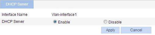
3. Select the Enable option for DHCP Server.
4. Click Apply.
Figure 43 Configuring a DHCP server interface
Displaying the information of assigned IP addresses
1. From the navigation tree, select Network > DHCP > DHCP Server to enter the page, as shown in Figure 40.
2. In the Address In Use area, view the information about the IP address assigned from the address pool.
Table 16 Description of the assigned IP address
|
Item |
Description |
|
IP Address |
Assigned IP address. |
|
Client MAC Address/Client ID |
Client MAC address or client ID bound to the IP address. |
|
Pool Name |
Name of the DHCP address pool where the IP address belongs. |
|
Lease Expiration |
Lease time of the IP address. |
DHCP server configuration example
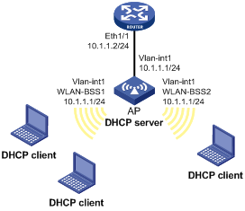
Network requirements
As shown in Figure 44, DHCP clients on subnet 10.1.1.0/24 obtain IP addresses dynamically from the DHCP server (AP). The IP address of VLAN-interface 1 of the AP is 10.1.1.1/24.
In subnet 10.1.1.0/24, the address lease duration is ten days and twelve hours and the gateway address is 10.1.1.2.
Configuring the DHCP server
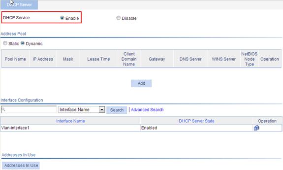
1. Enable DHCP:
a. From the navigation tree, select Network > DHCP to enter the default DHCP Server page.
b. Select the Enable option for DHCP Service, as shown in Figure 45.
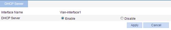
2. Enable the DHCP server on VLAN-interface 1 (you can skip this step because the DHCP server is enabled on the interface by default):
a. Click the ![]() icon of Vlan-interface1.
icon of Vlan-interface1.
b. Select the Enable option for DHCP Server, as shown in Figure 46.
c. Click Apply.
Figure 46 Enable DHCP server on VLAN-interface 1
3. Configure a dynamic address pool for the DHCP server:
The Dynamic option in the Address Pool field is selected by default.
a. Click Add to enter the page shown in Figure 47.
b. Enter test for IP Pool Name.
c. Enter 10.1.1.0 for IP Address.
d. Enter 255.255.255.0 for Mask.
e. Enter 10 days 12 hours 0 minutes 0 seconds for Lease Duration.
f. Enter 10.1.1.2 for Gateway Address.
g. Click Apply.
Figure 47 Configuring a dynamic address pool for the DHCP server
Overview
Domain Name System (DNS) is a distributed database used by TCP/IP applications to translate domain names into corresponding IP addresses. With DNS, you can use easy-to-remember domain names in some applications and let the DNS server translate them into correct IP addresses.
There are two types of DNS services, static and dynamic. After a user specifies a name, the device checks the local static name resolution table for an IP address. If no IP address is available, it contacts the DNS server for dynamic name resolution, which takes more time than static name resolution. Therefore, some frequently queried name-to-IP address mappings are stored in the local static name resolution table to improve efficiency.
Static domain name resolution
Configuring static domain name resolution is to set up mappings between domain names and IP addresses manually. IP addresses of the corresponding domain names can be found in the static domain resolution table when you use applications such as Telnet.
Dynamic domain name resolution
Dynamic domain name resolution is implemented by querying the DNS server.
Recommended configuration procedure
Configuring static name resolution table
|
Task |
Remarks |
|
Required. By default, no host name-to-IP address mappings are configured in the static domain name resolution table. |
Configuring dynamic domain name resolution
|
Step |
Remarks |
|
Required. Enable dynamic domain name resolution. This function is disabled by default. |
|
|
Required. Not configured by default. |
|
|
Optional. Not configured by default. |
|
|
Optional. |
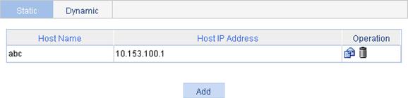
Configuring static name resolution table
1. From the navigation tree, select Network > DNS to enter the default static domain name resolution configuration page shown in Figure 48.
Figure 48 Static domain name resolution configuration page
2. Click Add to enter the page shown in Figure 49.
Figure 49 Creating a static domain name resolution entry
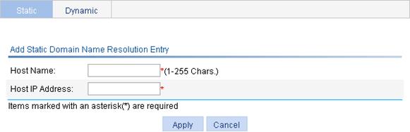
3. Configure the static name resolution table, as described in Table 17.
4. Click Apply.
|
Item |
Description |
|
Host Name |
Configure the mapping between a host name and an IP address in the static domain mane table. Each host name corresponds to only one IP address. If you configure multiple IP addresses for a host name, the last configured address takes effect. You can create up to 50 static host name-to-IP address mappings. |
|
Host IP Address |
Configuring dynamic domain name resolution
1. From the navigation tree, select Network > DNS.
2. Click the Dynamic tab to enter the page shown in Figure 50.
3. Select the Enable option for Dynamic DNS.
4. Click Apply.
Figure 50 Dynamic domain name resolution configuration page

Adding a DNS server address
1. From the navigation tree, select Network > DNS.
2. Click the Dynamic tab to enter the page shown in Figure 50.
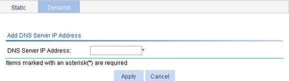
3. Click Add IP to enter the page shown in Figure 51.
4. Enter an IP address in the DNS Server IP address field.
5. Click Apply.
Figure 51 Adding a DNS server address
Adding a domain name suffix
1. From the navigation tree, select Network > DNS.
2. Click the Dynamic tab to enter the page shown in Figure 50.
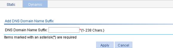
3. Click Add Suffix to enter the page shown in Figure 52.
4. Enter a DNS suffix in the DNS Domain Name Suffix field.
5. Click Apply.
Figure 52 Add a domain name suffix
Clearing dynamic DNS cache
1. From the navigation tree, select Network > DNS.
2. Click the Dynamic tab to enter the page shown in Figure 50.
3. Select the Clear dynamic DNS cache box.
4. Click Apply.
DNS configuration example
Network requirements
As shown in Figure 53, the AC wants to access the host by using an easy-to-remember domain name rather than an IP address.
The IP address of the DNS server is 2.1.1.2/16 and the domain name suffix is com. The AP serving as a DNS client uses dynamic domain name resolution to access the host with the domain name host.com and the IP address 3.1.1.1/16.
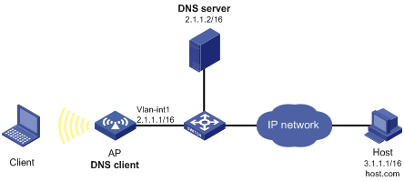
Before performing this configuration, make sure that the AP and the host can reach each other, and related configurations have been made on both the AP and the host. For the IP addresses of the interfaces, see Figure 53.
This configuration may vary with DNS servers. The following configuration is performed on a PC running Windows Server 2000.
Configuring the DNS server
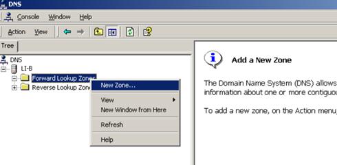
1. Create zone com:
a. Select Start > Programs > Administrative Tools > DNS.
b. As shown in Figure 54, right-click Forward Lookup Zones and select New Zone.
c. Follow the wizard to create a new zone named com.
2. Create a mapping between host name and IP address:
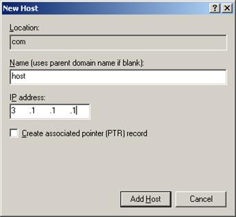
a. In Figure 55, right-click zone com, and then select New Host to bring up a dialog box as shown in Figure 56.
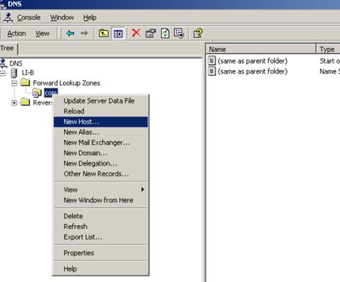
b. Enter host name host and IP address 3.1.1.1.
c. Click Add Host.
Figure 56 Adding a mapping between domain name and IP address
Configuring the AP
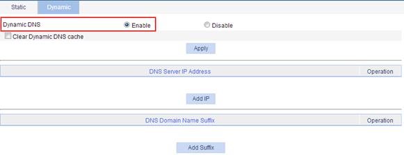
1. Enable dynamic domain name resolution:
a. From the navigation tree, select Network > DNS.
b. Click the Dynamic tab.
c. Select the Enable option for Dynamic DNS.
d. Click Apply.
Figure 57 Enabling dynamic domain name resolution
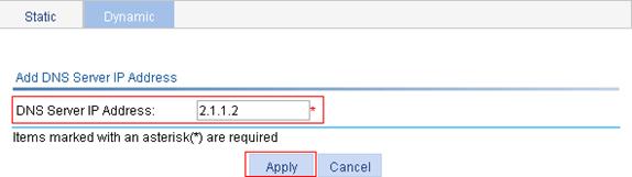
2. Configure the DNS server address:
a. Click Add IP on the Dynamic tab.
b. Enter 2.1.1.2 for DNS Server IP Address.
c. Click Apply.
Figure 58 Add a DNS server address
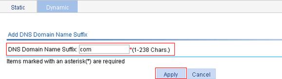
3. Configure the domain name suffix:
a. Click the Add Suffix button on the Dynamic tab.
b. Enter com for DNS Domain Name Suffix.
c. Click Apply.
Figure 59 Adding a domain name suffix
Verifying the configuration
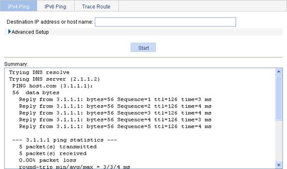
Use the ping host command on the AP to verify that the communication between the AP and the host is normal and that the corresponding destination IP address is 3.1.1.1.
1. From the navigation tree, select Network > Diagnostic Tools to enter the IPv4 Ping page.
2. Enter host in the field of Destination IP address or host name.
3. Click Start.
4. The Summary field displays the ping operation result, as shown in Figure 60.
Figure 60 Ping operation result
Overview
Point-to-Point Protocol over Ethernet (PPPoE) uses the client/server model. It establishes point-to-point links over Ethernet, and encapsulates PPP packets in Ethernet frames.
APs configured as PPPoE clients can be connected to the Internet through a remote access device, and access control and accounting can be implemented on a per-AP basis.
PPPoE undergoes two phases:
· Discovery phase—Where a PPPoE session is initiated. In this phase, the client obtains the MAC address of the access end and generates the PPPoE session ID.
· PPP session phase—Where PPP packets are encapsulated in Ethernet frames before being sent to the peer.
In the frame, the session ID must be the one determined in the discovery phase, the MAC address must be that of the peer, and the PPP packet section begins from the Protocol ID field. In the session phase, either end of the link can terminate the session by sending PPPoE Active Discovery Terminate (PADT) packets.
For more information about PPPoE, see RFC 2516.
Figure 61 PPPoE application scenario
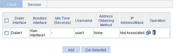
Configuring a PPPoE client
1. Select Network > PPPoE from the navigation tree.
The system automatically enters the Client page.
Figure 62 PPPoE client information
2. Click Add to enter the page for creating a PPPoE client.
Figure 63 Creating a PPPoE client
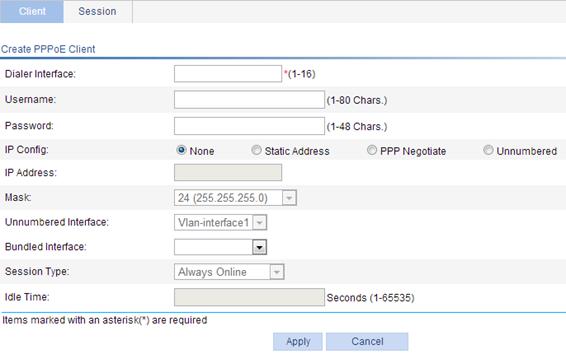
3. Configure the parameters for the PPPoE client, as described in Figure 64.
4. Click Apply.
|
Task |
Remarks |
|
Dialer Interface |
Configure the number of the dialer interface. |
|
Username |
Configure the username and password used by the PPPoE client in authentication. The username and password must be configured together, or not configured at all. |
|
Password |
|
|
IP Config |
Configure the way the dialer interface obtains its IP address: · None—Does not configure an IP address. · Static Address—Statically configures an IP address and subnet mask for the interface. · PPP Negotiate—Obtains an IP address through PPP negotiation. · Unnumbered—Borrows the IP address of another interface on the same device. |
|
IP Address |
Configure an IP address and subnet mask for the dialer interface. If you select Static Address to configure a static IP address for the dialer interface, you must configure both items. |
|
Mask |
|
|
Unnumbered Interface |
Interfaces on the same device whose IP addresses are borrowed. If you select IP address borrowing for the dialer interface, you need to configure this item. |
|
Bundled Interface |
Configure the interfaces bound to the PPPoE client. |
|
Session Type |
Set the session type of the PPPoE client: · Always Online—When the physical link is up, the device immediately initiates a PPPoE call to establish a PPPoE session. The PPPoE session continues to exist until you delete it. · Not Always Online—When the physical link is up, the device does not initiate a PPPoE call unless there is data to be transmitted on the link. When the PPPoE link stays in the idle state longer than the timeout timer set by the user, the device terminates the current PPPoE session automatically. When you select the non-permanent connection mode, you must set an idle-timeout timer. |
|
Idle Time |
Set an idle-timeout timer for the PPPoE link. This item is required when you set the session type to Not Always Online. |
Displaying PPPoE client session statistic information
1. Select Network > PPPoE from the navigation tree.
2. Click the Session tab to enter the page for displaying the session information.
3. Select Statistic Information to be displayed about the PPPoE session.
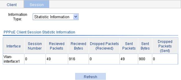
Table 19 Field description
|
Field |
Description |
|
Interface |
Ethernet interface where the PPPoE session belongs. This field is null when the PPPoE session is bundled with a VLAN interface. |
|
Session Number |
PPPoE session ID. |
|
Received Packets |
Number of received packets in the PPPoE session. |
|
Received Bytes |
Number of received bytes in the PPPoE session. |
|
Dropped Packets (Received) |
Number of dropped packets which are received in the PPPoE session. |
|
Sent Packets |
Number of transmitted packets in the PPPoE session. |
|
Sent Bytes |
Number of transmitted bytes in the PPPoE session. |
|
Dropped Packets (Sent) |
Number of dropped packets which are transmitted in the PPPoE session. |
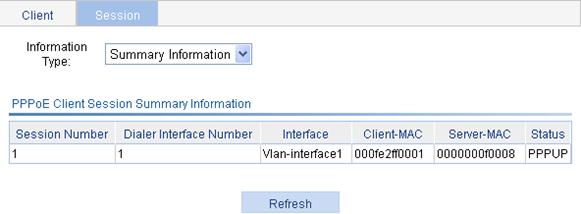
Displaying PPPoE client session information
1. Select Network > PPPoE from the navigation tree.
2. Click the Session tab to enter the page for displaying the session information.
3. Select Summary Information to be displayed about the PPPoE session.
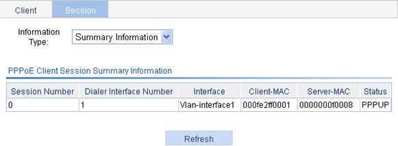
Table 20 Field description
|
Field |
Description |
|
Session Number |
PPPoE session ID. |
|
Dialer Interface Number |
Number of the dialer interface corresponding to the PPPoE session. |
|
Interface |
Ethernet interface where the PPPoE session belongs. This field is null when the PPPoE session is bundled with a VLAN interface. |
|
Client-MAC |
MAC address of the PPPoE client. |
|
Server-MAC |
MAC address of the PPPoE server. |
|
Status |
PPPoE session state: · IDLE—PPPoE client negotiation is not performed. · PADI—PADI packets have been sent. The interface is waiting for the PADO response. · PADR—PADR packets have been sent. The interface is waiting for the PADS response. · PPPNEG—PPP negotiation is started. · PPPUP—PPP negotiation is completed. |
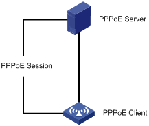
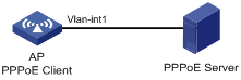
PPPoE client configuration example
Network requirements
Configure PPPoE client on the AP and enable the PPPoE client to communicate with the PPPoE server, as shown in Figure 66.
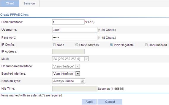
Configuring the PPPoE client
1. Configure the PPPoE client:
a. Select Network > PPPoE from the navigation tree. The system automatically enters the Client page.
b. Click Add.
c. Enter 1 as the dialer interface name.
d. Enter user1 as the username.
e. Enter hello as the password.
f. Select the IP configuration mode as PPP Negotiate.
g. Select the interface to be bound as Vlan-interface1.
h. Select the session type as Always Online.
i. Click Apply.
Figure 67 Creating a PPPoE client
2. Configure the PPPoE server:
You must enable the PPPoE protocol on the PPPoE server, configure the PPPoE username and password that are the same as those configured on the PPPoE client, and assign an IP address to the peer end of the PPP connection. Detailed configurations will not be further discussed here.
Verifying the configuration
Display the summary information of the PPPoE session on an AP.
1. Select Network > PPPoE from the navigation tree of the AP and click the Session tab.
2. Select Summary Information for the Information Type field.
Figure 68 shows that the PPP session is completed.
Figure 68 Displaying the summary information of PPPoE sessions
Configuration guidelines
The dialer interfaces you create on the page generated after you select Device > Interface Management can also be displayed on the PPPoE client page. On this page, you can modify or remove these dialer interfaces as well. However, you cannot establish PPPoE sessions for them.
Overview
Service management allows you to manage the following types of services: Telnet, SSH, SFTP, HTTP, and HTTPS.
You can enable or disable the services, modify HTTP and HTTPS port numbers, and associate the HTTP or HTTPS service with an ACL to block illegal users.
Telnet service
Telnet is an application layer protocol that provides remote login and virtual terminal functions.
SSH service
Secure Shell (SSH) offers an approach to securely logging in to a remote device. By encryption and strong authentication, it protects devices against attacks such as IP spoofing and plain text password interception.
SFTP service
The secure file transfer protocol (SFTP) is a new feature in SSH2.0. SFTP uses the SSH connection to provide secure data transfer. The device can serve as the SFTP server, allowing a remote user to log in to the SFTP server for secure file management and transfer. The device can also serve as an SFTP client, enabling a user to login from the device to a remote device for secure file transfer.
HTTP service
HTTP is used for transferring webpage information across the Internet. It is an application-layer protocol in the TCP/IP protocol suite.
You can log in to the device by using the HTTP protocol with HTTP service enabled, accessing and controlling the device with Web-based network management.
HTTPS service
The Hypertext Transfer Protocol Secure (HTTPS) refers to the HTTP protocol that supports the Security Socket Layer (SSL) protocol.
The SSL protocol of HTTPS enhances the security of the device in the following ways:
· Uses the SSL protocol to ensure the legal clients to access the device securely and prohibit the illegal clients.
· Encrypts the data exchanged between the HTTPS client and the device to ensure the data security and integrity.
· Defines certificate attribute-based access control policy for the device to control user access.
Managing services
1. Select Network > Service from the navigation tree to enter the service management configuration page, as shown in Figure 69.
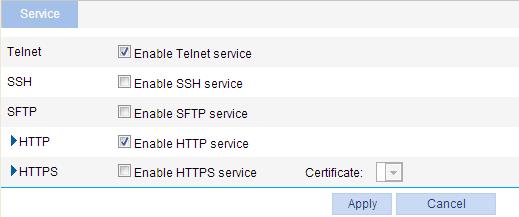
2. Enable or disable various services on the page. Table 21 describes the detailed configuration items.
3. Click Apply.
Table 21 Service management configuration items
|
Item |
Description |
|
|
Telnet |
Enable Telnet service. |
Enable or disable the Telnet service. The Telnet service is disabled by default. |
|
SSH |
Enable SSH service. |
Enable or disable the SSH service. The SSH service is disabled by default. |
|
SFTP |
Enable SFTP service. |
Enable or disable the SFTP service. The SFTP service is disabled by default.
When you enable the SFTP service, the SSH service must be enabled. |
|
HTTP |
Enable HTTP service. |
Enable or disable the HTTP service. The HTTP service is enabled by default. |
|
Port Number. |
Set the port number for HTTP service. You can view this configuration item by clicking the expanding button in front of HTTP.
When you modify a port, make sure the port is not used by any other service. |
|
|
ACL. |
Associate the HTTP service with an ACL. Only the clients that pass the ACL filtering are permitted to use the HTTP service. You can view this configuration item by clicking the expanding button in front of HTTP. |
|
|
HTTPS |
Enable HTTPS service. |
Enable or disable the HTTPS service. The HTTPS service is disabled by default. |
|
Certificate. |
Select a local certificate for the HTTPS service from the Certificate dropdown list. You can configure the certificates available in the dropdown list in Authentication > Certificate Management. For more information, see "Managing certificates."
If no certificate is specified, the HTTPS service generates its own certificate. |
|
|
Port Number. |
Set the port number for HTTPS service. You can view this configuration item by clicking the expanding button in front of HTTPS.
When you modify a port, make sure the port is not used by any other service. |
|
|
ACL. |
Associate the HTTPS service with an ACL. Only the clients that pass the ACL filtering are permitted to use the HTTPS service. You can view this configuration item by clicking the expanding button in front of HTTPS. |
|
This chapter describes how to use the ping and traceroute facilities.
Ping
You can ping the IP address or the host name of a device.
If the host name cannot be resolved, a prompt appears. If the source device does not receive any ICMP echo reply within the timeout time, it displays prompt information and ping statistics. If the source device receives ICMP echo replies within the timeout time, it displays the number of bytes for each echo reply, the message sequence number, Time to Live (TTL), the response time, and ping statistics. Ping statistics include the number of packets sent, number of echo reply messages received, percentage of messages not received, and the minimum, average, and maximum response time.
A ping operation involves the following steps:
1. The source device sends ICMP echo requests to the destination device.
2. The destination device responds by sending ICMP echo replies to the source device after receiving the ICMP echo requests.
3. The source device displays related statistics after receiving the replies.
Traceroute
By using the traceroute facility, you can display the Layer 3 devices involved in delivering a packet from source to destination. This function is useful for identification of failed nodes.
You can traceroute a host name or IP address. If the destination’s host name is unknown, a prompt appears.
A traceroute operation involves the following steps:
1. The source device sends a packet with a Time to Live (TTL) value of 1 to the destination device.
2. The first hop device responds with an ICMP TTL-expired message to the source. In this way, the source device can get the address of the first Layer 3 device.
3. The source device sends a packet with a TTL value of 2 to the destination device.
4. The second hop responds with an ICMP TTL-expired message.
5. The above process continues until the ultimate destination device is reached. The destination device responds with an ICMP port-unreachable message because the packet from the source has an unreachable port number. In this way, the source device can get the addresses of all Layer 3 devices on the path.
Ping operation
IPv4 ping operation
1. Select Diagnostic Tools > Ping from the navigation tree.
2. Click the expansion button before Advanced Setup to display the configurations of the advanced parameters of IPv4 ping operation, as shown in Figure 70.
Figure 70 IPv4 ping configuration page
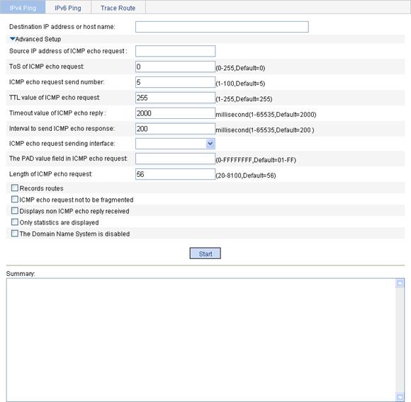
3. Type in the IPv4 address or host name of the destination device in the Destination IP address or host name box.
4. Set the advanced parameters for the IPv4 ping operation.
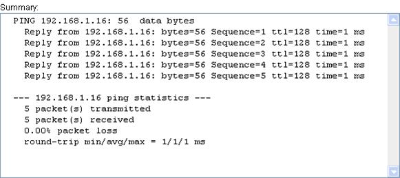
5. Click Start to execute the ping command.
6. View the result in the Summary box.
Figure 71 IPv4 ping operation results
IPv6 ping operation
1. Select Diagnostic Tools > Ping from the navigation tree.
2. Click the IPv6 Ping tab to enter the IPv6 ping configuration page.
3. Click the expansion button before Advanced Setup to display the configurations of the advanced parameters of IPv6 ping operation, as shown in Figure 72.
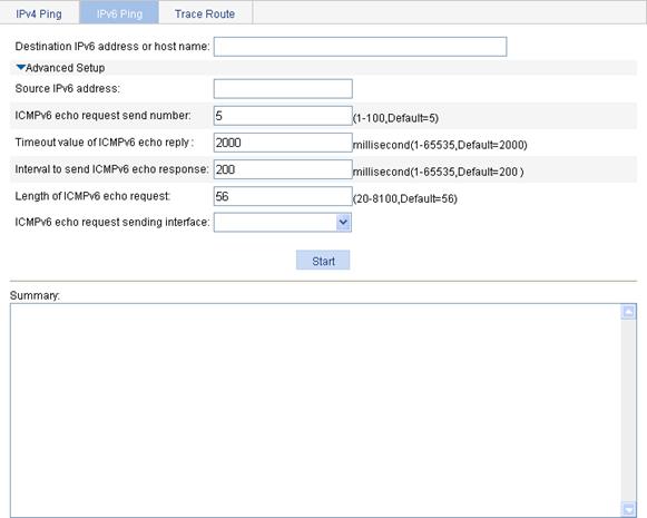
4. Type the IPv6 address or host name of the destination device in the Destination IP address or host name box
5. Set the advanced parameters for the IPv6 ping operation.
6. Click Start to execute the ping command.
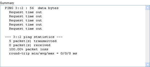
7. View the result in the Summary box, as shown in Figure 73.
Figure 73 IPv6 ping operation results
Traceroute operation
The Web interface does not support IPv6 traceroute.
Before performing a traceroute operation, execute the ip ttl-expires enable command on intermediate devices to enable the sending of ICMP timeout packets and the ip unreachables enable command on the destination device to enable the sending of ICMP destination unreachable packets.
To perform a traceroute operation:
1. Select Diagnostic Tools > Trace Route from the navigation tree.
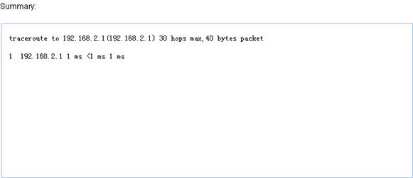
2. Click the Trace Route tab to enter the Trace Route configuration page, as shown in Figure 74.
Figure 74 Trace Route configuration page
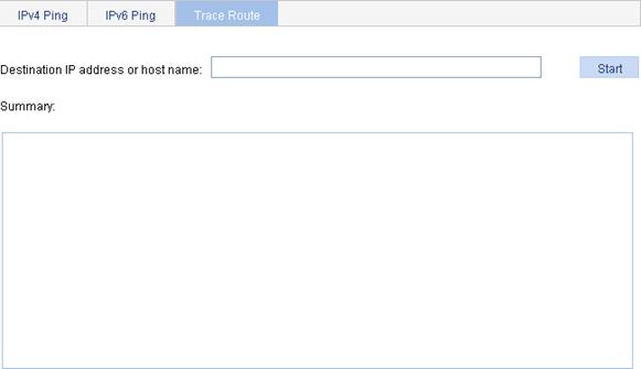
3. Enter the destination IP address or host name in the field
4. Click Start.
5. View the result in the Summary box, as shown in Figure 75.
Figure 75 Traceroute operation results