- Table of Contents
-
- 03-Basic Network Configuration
- 01-Layer 2 Static Link Aggregation Configuration Example
- 02-Layer 2 Dynamic Link Aggregation Configuration Example
- 03-PPPoE Client Configuration Example
- 04-Static IPv6 Address Configuration Example
- 05-IPv6 Static Routing Configuration Example
- 06-Static IPv4 DNS Configuration Example
- 07-Static IPv6 DNS Configuration Example
- 08-Dynamic IPv4 DNS Configuration Example
- 09-Dynamic IPv6 DNS Configuration Example
- 10-IPv4 DNS Proxy Configuration Example
- 11-IPv6 DNS Proxy Configuration Example
- 12-Static NAT Configuration Example
- 13-Dynamic NAT Configuration Example
- 14-IPv4 ACL-Based Packet Filter Configuration Example
- 15-IPv6 ACL-Based Packet Filter Configuration Example
- 16-ARP Attack Protection Configuration Example
- 17-ARP Proxy Configuration Example
- 18-IGMP Snooping Configuration Example
- 19-MLD Snooping Configuration Example
- Related Documents
-
| Title | Size | Download |
|---|---|---|
| 03-PPPoE Client Configuration Example | 136.25 KB |
|
|
|
H3C Access Controllers |
|
Comware 7 PPPoE Client |
|
Configuration Example |
Copyright © 2024 New H3C Technologies Co., Ltd. All rights reserved.
No part of this manual may be reproduced or transmitted in any form or by any means without prior written consent of New H3C Technologies Co., Ltd.
Except for the trademarks of New H3C Technologies Co., Ltd., any trademarks that may be mentioned in this document are the property of their respective owners.
The information in this document is subject to change without notice.
Contents
Example: Configuring the PPPoE client
Configuring the PPPoE server to assign the username and password to the AC
Overview
Point-to-Point Protocol over Ethernet (PPPoE) extends PPP by transporting PPP frames encapsulated in Ethernet over point-to-point links. PPPoE specifies the methods for establishing PPPoE sessions and encapsulating PPP frames over Ethernet. PPPoE requires a point-to-point relationship between peers instead of a point-to-multipoint relationship as in multi-access environments such as Ethernet. PPPoE provides Internet access for the hosts in an Ethernet through a remote access device and implement access control, authentication, and accounting on a per-host basis.
Integrating the low cost of Ethernet and scalability and management functions of PPP, PPPoE gained popularity in various application environments, such as residential access networks.
Prerequisites
The configuration examples were created and verified in a lab environment, and all the devices were started with the factory default configuration. When you are working on a live network, make sure you understand the potential impact of every command on your network.
The following information is provided based on the assumption that you have basic knowledge of the PPPoE client.
Example: Configuring the PPPoE client
Network configuration
As shown in Figure 1, the AC connects to the Internet as a PPPoE client through Layer 3 physical interface GigabitEthernet 1/0/1. Configure the PPPoE client to meet the following requirements:
· The PPPoE server and the AC can reach each other at Layer 3.
· Host can access the Internet through Telnetting to the IP address of GigabitEthernet 1/0/2 of the AC.

Restrictions and guidelines
When you configure the PPPoE client, follow these restrictions and guidelines:
· Only outgoing packets can reset the link-idle timeout timer.
· When configuring the PPPoE client, you must select the Remove existing interface address option. Select a proper Layer 3 physical interface as needed.
· After configuring PPPoE for an interface, do not assign an IP address to the interface manually or through DHCP.
Procedures
Configuring the PPPoE server to assign the username and password to the AC
Details not shown.
Configuring the PPPoE client
1. Click the System View tab at the bottom of the page.
2. From the navigation pane, select Network Configuration > Network Interfaces.
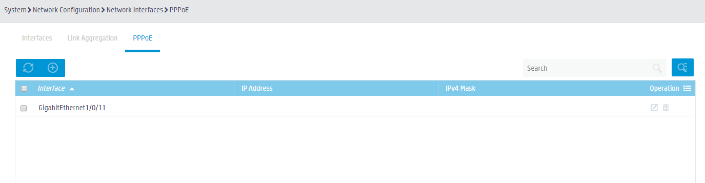
3. Click the PPPoE tab to enter the PPPoE configuration page, as shown in Figure 2.
4. Click the Add button
![]() to
enter the page for adding PPPoE configuration, as shown in Figure 3.
to
enter the page for adding PPPoE configuration, as shown in Figure 3.
Figure 2 PPPoE configuration page
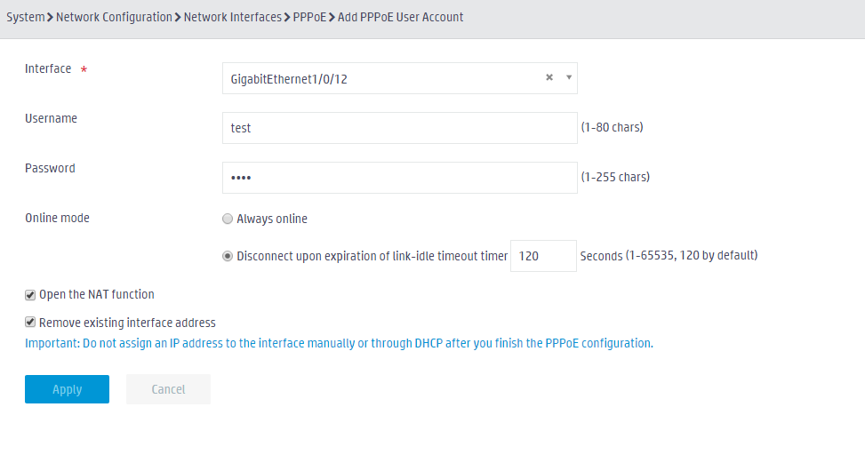
5. On the page as shown in Figure 3, perform the following tasks:
a. Select the Layer 3 physical interface to be configured (GigabitEthernet 1/0/1 in this example).
b. Enter the username and password.
c. Select an online mode.
d. Select the Open the NAT function and the Remove existing interface address options.
e. Click Apply.
Figure 3 Adding PPPoE configuration
Verifying the configuration
Configure a static route and send packets on the AC. View the traffic information to verify the configuration.
Related documentation
H3C Access Controllers Web-Based Configuration Guide