- Table of Contents
-
- 07-Wireless authentication
- 01-Local Portal Authentication Configuration Examples
- 02-HTTPS-Based Local Portal Authentication Configuration Examples
- 03-Remote Portal Authentication Configuration Examples
- 04-Local Portal Authentication through LDAP Server Configuration Examples
- 05-Local Portal Auth and SSID-based Auth Page Pushing Configuration Examples
- 06-Local Portal MAC-Trigger Authentication Configuration Examples
- 07-Portal MAC-Trigger Authentication Configuration Examples
- 08-Local Forwarding Mode and Local Portal MAC-Trigger Auth Configuration Examples
- 09-Local Portal Authentication (IPv6) Configuration Examples
- 10-Local Portal Authentication through LDAP Server (IPv6) Configuration Examples
- 11-Remote Portal Authentication (IPv6) Configuration Examples
- 12-Portal MAC-Trigger Authentication (IPv6) Configuration Example
- 13-Remote Portal Authentication with User Profile Authorization Configuration Examples
- 14-WiFiDog Portal Authentication Configuration Examples
- 15-Portal Fail-Permit Configuration Examples
- 16-Local MAC Authentication Configuration Examples
- 17-Remote MAC Authentication Configuration Examples
- 18-Transparent Auth Through Remote MAC and Portal Auth Configuration Examples
- 19-Remote AP, Remote Portal, and MAC-Trigger Authentication Configuration Examples
- 20-MAC Authentication with Guest VLAN Assignment Configuration Examples
- 21-MAC Authentication with Guest VLAN Assignment (IPv6) Configuration Examples
- 22-Local MAC-And-802.1X Authentication Configuration Examples
- 23-Local 802.1X Authentication Configuration Examples
- 24-Local RADIUS-Based 802.1X Authentication in EAP Relay Mode Configuration Examples
- 25-Remote 802.1X Authentication Configuration Examples
- 26-Remote 802.1X Authentication (IPv6) Configuration Examples
- 27-Remote 802.1X Authentication in WPA3-Enterprise Mode Configuration Examples
- 28-802.1X Auth with ACL Assignment Through IMC Server Configuration Examples
- 29-802.1X Auth with User Profile Assignment Through IMC Server Configuration Examples
- 30-EAD Authentication Configuration Examples
- 31-EAD Authentication (IPv6) Configuration Examples
- Related Documents
-
| Title | Size | Download |
|---|---|---|
| 14-WiFiDog Portal Authentication Configuration Examples | 93.31 KB |
|
|
|
H3C Access Controllers |
|
WiFiDog Portal Authentication |
|
Configuration Examples |
Copyright © 2023 New H3C Technologies Co., Ltd. All rights reserved.
No part of this manual may be reproduced or transmitted in any form or by any means without prior written consent of New H3C Technologies Co., Ltd.
Except for the trademarks of New H3C Technologies Co., Ltd., any trademarks that may be mentioned in this document are the property of their respective owners.
The information in this document is subject to change without notice.
Introduction
The following information provides an example of configuring WiFiDog portal authentication.
Prerequisites
The following information applies to Comware-based access controllers and access points. Procedures and information in the examples might be slightly different depending on the software or hardware version of the access controllers and access points.
The configuration examples were created and verified in a lab environment, and all the devices were started with the factory default configuration. When you are working on a live network, make sure you understand the potential impact of every command on your network.
The following information is provided based on the assumption that you have basic knowledge of portal authentication and WLAN access features.
Example: Configuring WiFiDog portal authentication
Network configuration
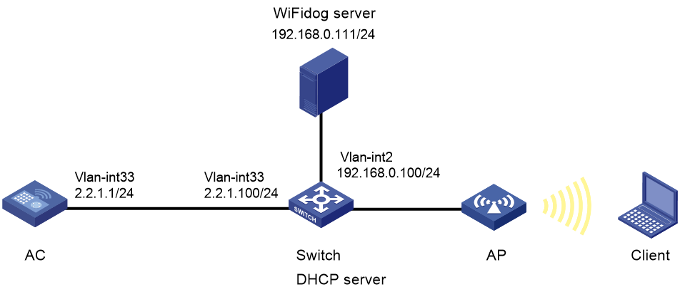
As shown in Figure 1:
· The AP and the client obtain IP addresses from the DHCP server.
· The WiFiDog server acts as the portal authentication server and the portal Web server.
· Direct portal authentication is configured for the client.
· An authenticated user can access network resources on any Layer 2 ports in its access VLAN without re-authentication.
Analysis
To allow an authenticated user to access network resources on any Layer 2 ports in its access VLAN without re-authentication, enable portal roaming.
To avoid possible authentication failure caused by frequent logins and logouts of portal clients in a short time, disable the Rule ARP entry feature for portal clients.
For portal packet exchange, configure portal-free rules to permit traffic among the portal Web server, the DNS server, and the AC.
For the client to access the portal Web server, configure a service port number on the WiFiDog server.
To use WiFiDog portal authentication, configure the AC to add the following parameters to the URL of the WiFiDog server when it redirects a portal user to the server:
· gw_address—IP address of the AC.
· gw_port—Port number of the WiFiDog service on the AC. By default, the port number is 80.
· gw_id—ID of the AC.
· mac—MAC address of the client.
· channel_path—Request channel. By default, the value is h3c.
· url—URL of the original webpage that the client visits.
· ip—IP address of the client.
Procedures
Configuring the WiFiDog server
Restrictions and guidelines
The configuration procedure and interface vary by WiFiDog server model and software version.
Procedure
# Specify the ID of the AC on the WiFiDog server. Perform this step for the WiFiDog server to identify the AC. The AC ID is user configurable and is unique in the network. In this example, configure the NAS ID of the AC as its ID on the WiFiDog server. (Details not shown.)
# Configure the password used to access the WiFiDog server. (Details not shown.)
# Configure a service port number on the WiFiDog server. The service port number is not fixed. In this example, the service port number is 12001. (Details not shown.)
Configuring the AC
1. Configure interfaces on the AC:
# Create VLAN 33 and VLAN-interface 33, and assign an IP address to the VLAN interface. The AC will use the IP address to establish CAPWAP data and control tunnels with the AP and use VLAN 33 for client access.
<AC> system-view
[AC] vlan 33
[AC-vlan33] quit
[AC] interface vlan-interface 33
[AC-Vlan-interface33] ip address 2.2.1.1 24
[AC-Vlan-interface33] quit
# Configure GigabitEthernet 1/0/2 (the port connected to the switch) as an access port and assign the port to VLAN 33.
[AC] interface gigabitethernet 1/0/2
[AC-GigabitEthernet1/0/2] port link-type access
[AC-GigabitEthernet1/0/2] port access vlan 33
[AC-GigabitEthernet1/0/2] quit
2. Configure a static route to reach the WiFiDog server.
[AC] ip route-static 192.168.0.0 255.255.0.0 2.2.1.100
3. Configure the AC to not perform authentication, authorization, and account for portal users in ISP domain po.
[AC] domain po
[AC-isp-po] authentication portal none
[AC-isp-po] authorization portal none
[AC-isp-po] accounting portal none
[AC-isp-po] quit
4. Create a portal authentication server named po. Specify the IP address of the WiFiDog server as the IP address of the authentication server, and specify the key for accessing the WiFiDog server.
[AC] portal server po
[AC-portal-server-po] ip 192.168.0.111 key simple wifitest
[AC-portal-server-po] quit
5. Configure the portal Web server:
# Create a portal Web server named web-po.
[AC] portal web-server web-po
# Specify the URL of the WiFiDog as the URL of the portal Web server and set the port number to 12001.
[AC-portal-websvr-web-po] url http://192.168.0.111:12001/wifidog
# Specify WiFiDog as the type of the portal Web server.
[AC-portal-websvr-web-po] server-type wifidog
# Add parameter channel_path to the URL of the portal Web server and set the parameter value to h3c. The AC redirects a portal user by sending the URL with the parameter to the user.
[AC-portal-websvr-web-po] url-parameter channel_path value h3c
# Add parameters gw_address, gw_id, and gw_port to the URL of the portal Web server. Specify the IP address of the AC, the ID of the AC, and the WiFiDog service port number of the AC as the values for the parameters, respectively. The AC redirects a portal user by sending the URL with the parameters to the user.
[AC-portal-websvr-web-po] url-parameter gw_address value 2.2.1.1
[AC-portal-websvr-web-po] url-parameter gw_id nas-id
[AC-portal-websvr-web-po] url-parameter gw_port value 80
# Add parameters ip, mac, ssid, and url to the URL of the portal Web server. Specify the client's IP address, the client's MAC address, the AP'S SSID, and the URL of the original webpage that the client visits as the values for the parameters, respectively. The AC redirects a portal user by sending the URL with the parameters to the user.
[AC-portal-websvr-web-po] url-parameter ip source-address
[AC-portal-websvr-web-po] url-parameter mac source-mac
[AC-portal-websvr-web-po] url-parameter ssid ssid
[AC-portal-websvr-web-po] url-parameter url original-url
[AC-portal-websvr-web-po]quit
6. Configure portal authentication rules:
# Configure destination-based portal-free rules to permit traffic destined for the portal Web server, the DNS server, and the AC.
[AC] portal free-rule 1 destination ip 8.8.8.8 255.255.255.255
[AC] portal free-rule 2 destination ip 114.114.114.114 255.255.255.255
[AC] portal free-rule 3 destination ip 2.2.1.1 255.255.255.255
[AC] portal free-rule 4 destination ip 192.168.0.111 255.255.255.255
# Enable validity check on wireless portal clients.
[AC] portal host-check enable
# Enable portal roaming.
[AC] portal roaming enable
# Disable the Rule ARP entry feature for portal clients.
[AC] undo portal refresh arp enable
7. Configure a wireless service:
# Create a service template named po and enter its view.
[AC] wlan service-template po
# Assign clients coming online through service template po to VLAN 33.
[AC-wlan-st-po] vlan 33
# Set the SSID to service.
[AC-wlan-st-po] ssid service
# Enable direct portal authentication in service template po.
[AC-wlan-st-po] portal enable method direct
# Specify ISP domain po as the portal authentication domain.
[AC-wlan-st-po] portal domain po
# Specify portal Web server web-po in service template po for portal authentication.
[AC-wlan-st-po] portal apply web-server web-po
# Configure the AC to forward client data traffic. (Skip this step if the client data forwarder is the AC by default.)
[AC–wlan-st-po] client forwarding-location ac
# Configure the AKM mode as PSK, and set the preshared key to 12345678 in plain text.
[AC-wlan-st-po] akm mode psk
[AC-wlan-st-po] preshared-key pass-phrase simple 12345678
# Configure the cipher suite as CCMP and security IE as RSN.
[AC-wlan-st-po] cipher-suite ccmp
[AC-wlan-st-po] security-ie rsn
# Enable the service template.
[AC-wlan-st-po] service-template enable
[AC-wlan-st-po]quit
8. Configure the AP:
|
|
NOTE: In large-scale networks, configure AP groups instead of single APs as a best practice. |
# Create an AP named ap1 with model WA6622 and set its serial ID to 219801A24H8199E0001C.
[AC] wlan ap ap1 model WA6622
[AC-wlan-ap-ap1] serial-id 219801A24H8199E0001C
# Create an AP group named group1 and create an AP grouping rule by AP names to add AP ap1 to AP group group1.
[AC] wlan ap-group group1
[AC-wlan-ap-group-group1] ap ap1
# Enter the AP group's radio 1 view, and bind service template po to radio 1.
[AC-wlan-ap-group-group1] ap-model WA6622
[AC-wlan-ap-group-group1-ap-model-WA6622] radio 1
[AC-wlan-ap-group-group1-ap-model-WA6622-radio-1] service-template po
# Enable radio 1.
[AC-wlan-ap-group-group1-ap-model-WA6622-radio-1] radio enable
[AC-wlan-ap-group-group1-ap-model-WA6622-radio-1] quit
# Enter the AP group's radio 2 view, and bind service template po to radio 2.
[AC-wlan-ap-group-group1-ap-model-WA6622] radio 2
[AC-wlan-ap-group-group1-ap-model-WA6622-radio-2] service-template po
# Enable radio 2.
[AC-wlan-ap-group-group1-ap-model-WA6622-radio-2] radio enable
[AC-wlan-ap-group-group1-ap-model-WA6622-radio-2] return
Configuring the switch
1. Configure DHCP:
# Enable DHCP.
[Switch] dhcp enable
# Create a DHCP address pool named 33 for allocating IP addresses to the AP and client.
[Switch] dhcp server ip-pool 33
# Specify a gateway address, a subnet, and a DNS server address in the DHCP address pool. In this example, the gateway address is the IP address of VLAN-interface 33 on the switch. The configuration is used for communication between the client and the WiFiDog server.
[Switch-dhcp-pool-33] gateway-list 2.2.1.100
[Switch-dhcp-pool-33] network 2.2.1.0 mask 255.255.255.0
[Switch-dhcp-pool-33] dns-list 8.8.8.8 114.114.114.114
[Switch-dhcp-pool-33] quit
2. Configure interfaces on the switch:
# Create VLAN 33 and VLAN-interface 33, assign an IP address to the VLAN interface, and apply DHCP address pool 33 to the VLAN interface.
<Switch> system-view
[Switch] vlan 33
[Switch-vlan33] quit
[Switch] interface vlan-interface 33
[Switch-Vlan-interface33] ip address 2.2.1.100 255.255.0.0
[Switch-Vlan-interface33] dhcp server apply ip-pool 33
[Switch-Vlan-interface33] quit
# Create VLAN 2. This VLAN is used to connect the WiFiDog server.
[Switch] vlan 2
[Switch-vlan2] quit
# Create VLAN-interface 2 and assign an IP address to the VLAN interface.
[Switch] interface vlan-interface 2
[Switch-Vlan-interface2] ip address 192.168.0.100 255.255.255.0
[Switch-Vlan-interface2] quit
# Configure GigabitEthernet 1/0/8 (the port connected to the AC) as an access port, and assign the port to VLAN 33.
[Switch] interface gigabitethernet 1/0/8
[Switch-GigabitEthernet1/0/8] port link-type access
[Switch-GigabitEthernet1/0/8] port access vlan 33
[Switch-GigabitEthernet1/0/8] quit
# Configure GigabitEthernet 1/0/10 (the port connected to the AP) as an access port, and assign the port to VLAN 33.
[Switch] interface gigabitethernet 1/0/10
[Switch-GigabitEthernet1/0/10] port link-type access
[Switch-GigabitEthernet1/0/10] port access vlan 33
# Enable PoE on GigabitEthernet 1/0/10.
[Switch-GigabitEthernet1/0/10] poe enable
[Switch-GigabitEthernet1/0/10] quit
# Configure GigabitEthernet 1/0/5 (the port connected to the WiFiDog server) as an access port, and assign the port to VLAN 2.
[Switch] interface gigabitethernet 1/0/5
[Switch-GigabitEthernet1/0/5] port link-type access
[Switch-GigabitEthernet1/0/5] port access vlan 2
[Switch-GigabitEthernet1/0/5] quit
Verifying the configuration
# On the client, connect to the wireless network with SSID service. Before passing portal authentication, the client can access only authentication page http://192.168.0.111:12001/wifidog. All Web requests from the client will be redirected to the authentication page. After passing portal authentication, the client can access other network resources. (Details not shown.)
# On the AC, display information about all portal users to verify that a portal user has come online.
[AC] display portal user all
Total portal users: 1
Username: a4:c9:39:68:7d:31
AP name: ap1
Radio ID: 1
SSID: service
Portal server: N/A
State: Online
VPN instance: N/A
MAC IP VLAN Interface
a4c9-3968-7d31 2.2.1.14 33 WLAN-BSS1/0/126
Authorization information:
DHCP IP pool: N/A
User profile: N/A
Session group profile: N/A
ACL number: N/A
Inbound CAR: N/A
Outbound CAR: N/A
Total number of clients: 1
Configuration files
· AC:
#
vlan 33
#
ip route-static 192.168.0.0 16 2.2.1.100
#
interface Vlan-interface33
ip address 2.2.1.1 255.255.0.0
#
interface GigabitEthernet1/0/2
port link-type access
port access vlan 33
#
wlan service-template po
ssid service
client forwarding-location ac
akm mode psk
preshared-key pass-phrase simple 12345678
cipher-suite ccmp
security-ie rsn
vlan 33
portal enable method direct
portal domain po
portal apply web-server web-po
service-template enable
#
domain po
authentication portal none
authorization portal none
accounting portal none
#
portal host-check enable
portal free-rule 1 destination ip 8.8.8.8 255.255.255.255
portal free-rule 2 destination ip 114.114.114.114 255.255.255.255
portal free-rule 3 destination ip 2.2.1.1 255.255.255.255
portal free-rule 4 destination ip 192.168.0.111 255.255.255.255
#
portal web-server web-po
url http://192.168.0.111:12001/wifidog
server-type wifidog
url-parameter channel_path value h3c
url-parameter gw_address value 2.2.1.1
url-parameter gw_id nas-id
url-parameter gw_port value 80
url-parameter ip source-address
url-parameter mac source-mac
url-parameter ssid ssid
url-parameter url original-url
#
portal server po
ip 192.168.0.111 key cipher $c$3$IXTLQ8lWluD9vHD/OC26sera+vnHj0yEKsuT
#
wlan ap ap1 model WA6622
serial-id 219801A24H8199E0001C
#
wlan ap-group group1
ap ap1
ap-model WA6622
radio 1
radio enable
service-template po
radio 2
radio enable
service-template po
· Switch:
#
dhcp enable
#
vlan 33
#
vlan 2
#
dhcp server ip-pool 33
gateway-list 2.2.1.100
network 2.2.1.100. mask 255.255.255.0
dns-list 8.8.8.8 114.114.114.114
#
interface Vlan-interface33
ip address 2.2.1.100 255.255.0.0
dhcp server apply ip-pool 33
#
interface Vlan-interface2
ip address 192.168.0.100 255.255.255.0
#
interface GigabitEthernet1/0/8
port link-type access
port access vlan 33
#
interface GigabitEthernet1/0/10
port link-type access
port access vlan 33
poe enable
#
interface GigabitEthernet1/0/5
port link-type access
port access vlan 2
#
Related documentation
· User Access and Authentication Configuration Guide in H3C Access Controllers Configuration Guides
· User Access and Authentication Command Reference in H3C Access Controllers Command References
· WLAN Access Configuration Guide in H3C Access Controllers Configuration Guides
· WLAN Access Command Reference in H3C Access Controllers Command References
