- Table of Contents
-
- 04-CLI configuration examples (AP standalone)
- 01-WPA2-PSK Encryption Configuration Examples
- 02-Client Rate Limiting Configuration Examples
- 03-NAT Configuration Examples
- 04-PPPoE Configuration Examples
- 05-Mesh WDS Configuration Examples
- 06-Local MAC Authentication (IPv6) Configuration Examples
- 07-IPv6 Configuration Examples
- 08-Layer 2 IPv6 Multicast Configuration Examples
- 09-Interoperation of Fat APs and Switch for WLAN Access and Roaming Configuration Examples
- 10-Remote 802.1X Authentication Configuration Examples
- 11-Remote MAC Authentication Configuration Examples
- 12-Anchor AC Mode Local Forwarding Configuration Examples
- 13-Anchor AC Mode Dual-Link Backup Configuration Examples
- 14-Anchor AC Mode Internal-to-External Access Through NAT Configuration Examples
- 15-Anchor AC Mode Remote Portal Auth in Local Forwarding Configuration Examples
- 16-Anchor AC Mode Remote Portal Auth in Centralized Forwarding Configuration Examples
- 17-Anchor AC Mode Remote 802.1X Auth in Local Forwarding Configuration Examples
- 18-Anchor AC Mode Remote 802.1X Auth in Centralized Forwarding Configuration Examples
- 19-Anchor AC Mode Remote AP Configuration Examples
- Related Documents
-
| Title | Size | Download |
|---|---|---|
| 12-Anchor AC Mode Local Forwarding Configuration Examples | 352.21 KB |
|
|
|
H3C Anchor Access Points in AC Mode |
|
Local Forwarding Configuration Examples |
|
|
Copyright © 2022 New H3C Technologies Co., Ltd. All rights reserved.
No part of this manual may be reproduced or transmitted in any form or by any means without prior written consent of New H3C Technologies Co., Ltd.
Except for the trademarks of New H3C Technologies Co., Ltd., any trademarks that may be mentioned in this document are the property of their respective owners.
The information in this document is subject to change without notice.
Overview
The following information provides an example for configuring local forwarding by an anchor AP that acts as an AC.
Prerequisites
The following information applies to Comware 7-based access controllers and access points. Procedures and information in the examples might be slightly different depending on the software or hardware version of the H3C access controllers.
The configuration examples were created and verified in a lab environment, and all the devices were started with the factory default configuration. When you are working on a live network, make sure you understand the potential impact of every command on your network.
The following information is provided based on the assumption that you have basic knowledge of local forwarding.
Example: Configuring local forwarding
The AC in this example is an anchor AP that operates as an AC.
Network configuration
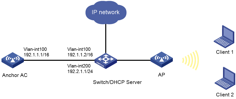
As shown in Figure 1, the switch acts as a DHCP server to assign IP addresses to the AP and the clients. Configure local forwarding on the AC for the AP to forward the client traffic.
Restrictions and guidelines
· Use the serial ID labeled on the AP's rear panel to specify an AP.
· For XGE 1/0/1 on the AP to join VLAN 200, activate remote configuration synchronization on the AC. Alternatively, edit the AP configuration file, and deploy it to the AP.
· Configure the switch to permit VLAN 200.
Procedure
Configuring the switch
1. Configure interfaces on the switch:
# Create VLAN 100, VLAN 200, VLAN-interface 100, and VLAN-interface 200, and assign an IP address to the VLAN interfaces. The AC will use VLAN-interface 100 to forward traffic on the CAPWAP tunnel between the AC and the AP and use VLAN-interface 200 to forward client traffic.
<Switch> system-view
[Switch] vlan 100
[Switch-vlan100] quit
[Switch] interface vlan-interface 100
[Switch-Vlan-interface100] ip address 192.1.1.2 16
[Switch-Vlan-interface100] quit
[Switch] vlan 200
[Switch-vlan200] quit
[Switch] interface vlan-interface 200
[Switch-Vlan-interface200] ip address 192.2.1.1 24
[Switch-Vlan-interface200] quit
# Configure GigabitEthernet 1/0/1 that connects the switch to the AC as a trunk port, and assign the port to VLAN 100.
[Switch] interface GigabitEthernet 1/0/1
[Switch-GigabitEthernet1/0/1] port link-type trunk
[Switch-GigabitEthernet1/0/1] port trunk permit vlan 100
[Switch-GigabitEthernet1/0/1] quit
# Configure GigabitEthernet 1/0/2 that connects the switch to the AP as a trunk port, remove the port from VLAN 1, and assign the port to VLAN 100 and VLAN 200. Set the PVID to 100.
[Switch] interface GigabitEthernet 1/0/2
[Switch-GigabitEthernet1/0/2] port link-type trunk
[Switch-GigabitEthernet1/0/2] undo port trunk permit vlan 1
[Switch-GigabitEthernet1/0/2] port trunk permit vlan 100 200
[Switch-GigabitEthernet1/0/2] port trunk pvid vlan 100
# Enable PoE on GigabitEthernet 1/0/2 that connects the switch to the AP.
[Switch-GigabitEthernet1/0/2] poe enable
[Switch-GigabitEthernet1/0/2] quit
2. Configure the DHCP service.
# Enable DHCP.
[Switch] dhcp enable
# Create DHCP address pool vlan100, specify subnet 192.1.0.0/16 for dynamic allocation, exclude 192.1.0.1 from dynamic allocation, and specify gateway IP address 192.1.0.2.
[Switch] dhcp server ip-pool vlan100
[Switch-dhcp-pool-vlan100] network 192.1.0.0 mask 255.255.0.0
[Switch-dhcp-pool-vlan100] forbidden-ip 192.1.1.1
[Switch-dhcp-pool-vlan100] gateway-list 192.1.1.2
[Switch-dhcp-pool-vlan100] quit
# Configure DHCP address pool vlan200. In the address pool, specify 192.2.1.1 as the gateway IP address, 192.2.1.0/24 as the subnet for dynamic allocation, and 192.2.1.1 as the DNS server address.
[Switch] dhcp server ip-pool vlan200
[Switch-dhcp-pool-vlan200] network 192.2.1.0 mask 255.255.255.0
[Switch-dhcp-pool-vlan200] gateway-list 192.2.1.1
[Switch-dhcp-pool-vlan200] dns-list 192.2.1.1
[Switch-dhcp-pool-vlan200] quit
Configuring the AC
1. Configure interfaces on the anchor AC:
# Create VLAN 100 and VLAN-interface 100, and assign an IP address to the VLAN interface. The AP will use this IP address to establish a CAPWAP tunnel with the AC.
<AC> system-view
[AC] vlan 100
[AC-vlan100] quit
[AC] interface vlan-interface 100
[AC-Vlan-interface100] ip address 192.1.1.1 16
[AC-Vlan-interface100] quit
# Configure XGE 1/0/1 that connects the AC to the switch as a trunk port, and assign the trunk port to VLAN 100.
[AC] interface Ten-GigabitEthernet 1/0/1
[AC-Ten-GigabitEthernet1/0/1] port link-type trunk
[AC-Ten-GigabitEthernet1/0/1] port trunk permit vlan 100
[AC-Ten-GigabitEthernet1/0/1] quit
2. Configure a wireless service:
# Create service template 1 and enter its view.
[AC] wlan service-template 1
# Configure the SSID as service.
[AC-wlan-st-1] ssid service
# Specify VLAN 200 in the service template.
[AC-wlan-st-1] vlan 200
# Enable local forwarding.
[AC-wlan-st-1] client forwarding-location ap
# Enable the service template.
[AC-wlan-st-1] service-template enable
[AC-wlan-st-1] quit
3. Configure AP
# Create a manual AP named 6630x, and specify the AP model and serial ID.
[AC] wlan ap 6630x model WA6630X-JP
[AC-wlan-ap-6630x] serial-id 219801A24G8212E0008J
# Enter the view of radio 2, and bind service template 1 to radio 2.
[AC-wlan-ap-6630x] radio 2
[AC-wlan-ap-6630x-radio-2] service-template 1
# Enable radio 2.
[AC-wlan-ap-6630x-radio-2] radio enable
[AC-wlan-ap-6630x-radio-2] quit
4. Configure remote configuration synchronization for XGE 1/0/1 on the AP to join VLAN 200.
# Create VLAN 200.
[AC-wlan-ap-6630x] vlan 200
[AC-wlan-ap-6630x-vlan200] quit
# Configure XGE 1/0/1 that connects the AP to the switch as a trunk port, and assign the trunk port to all VLAN.
[AC-wlan-ap-6630x] ten-gigabitEthernet 1
[AC-wlan-ap-6630x-ten-gigabitEthernet1] port link-type trunk
[AC-wlan-ap-6630x-ten-gigabitEthernet1] port trunk permit vlan all
[AC-wlan-ap-6630x-ten-gigabitEthernet1] port trunk pvid vlan 1
[AC-wlan-ap-6630x-ten-gigabitEthernet1] quit
# Enable the remote configuration assignment feature.
[AC-wlan-ap-6630x] remote-configuration enable
# Activate remote configuration synchronization.
[AC-wlan-ap-6630x] remote-configuration synchronize
5. Alternatively, deploy the configuration file of the AP for XGE 1/0/1 on the AP to join VLAN 200.
Copy the following text to a text file and upload the file to the AC. After the AP is associated with the AC, the map-configuration command deploys the configuration file to the AP.
# apcfg.txt configuration file:
system-view
vlan 200
quit
interface Ten-GigabitEthernet 1/0/1
port link-type trunk
port trunk permit vlan 200
# Deploy configuration file apcfg.txt to the AP.
[AC-wlan-ap-6630x] map-configuration apcfg.txt
[AC-wlan-ap-6630x] quit
Verifying the configuration
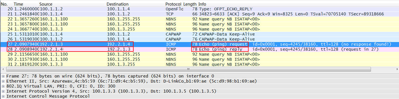
# Verify that Client 1 can Client 2 obtain IP address 192.2.1.3 and 192.2.1.4, respectively, and ICMP packets are not encapsulated in the CAPWAP tunnel but are forwarded directly.
Figure 2 Local forwarding of ICMP packets
Configuration files
· AC (anchor AP):
#
Vlan 100
#
wlan service-template 1
ssid service
vlan 200
client forwarding-location ap
service-template enable
#
interface Vlan-interface100
ip address 192.1.1.1 255.255.0.0
#
interface Ten-GigabitEthernet1/0/1
port link-type trunk
port trunk permit vlan 100 200
#
wlan ap 6630x model WA6630X-JP
vlan 200
serial-id 219801A24G8212E0008J
remote-configuration enable
remote-configuration synchronize
radio 2
radio enable
service-template 1
remote-configuration enable
remote-configuration synchronize
ten-gigabitEthernet 1
port link-type trunk
port trunk permit vlan all
port trunk pvid vlan 1
#
· Switch:
#
dhcp enable
#
vlan 100
#
vlan 200
#
dhcp server ip-pool vlan100
gateway-list 192.1.1.2
network 192.1.0.0 mask 255.255.0.0
forbidden-ip 192.1.1.1
#
dhcp server ip-pool vlan200
gateway-list 192.2.1.1
network 192.2.1.0 mask 255.255.255.0
dns-list 192.2.1.1
#
interface Vlan-interface100
ip address 192.1.1.2 255.255.0.0
#
interface Vlan-interface200
ip address 192.2.1.1 255.255.255.0
#
interface GigabitEthernet1/0/1
port link-mode bridge
port link-type trunk
port trunk permit vlan 1 100
#
interface GigabitEthernet1/0/2
port link-mode bridge
port link-type trunk
undo port trunk permit vlan 1
port trunk permit vlan 100 200
port trunk pvid vlan 100
#
Related documentation
· WLAN Access Command Reference in H3C Access Points Anchor AC Mode Configuration Guides
· WLAN Access Configuration Guide in H3C Access Points Anchor AC Mode Configuration Guides
