- Table of Contents
-
- 04-CLI configuration examples (AP standalone)
- 01-WPA2-PSK Encryption Configuration Examples
- 02-Client Rate Limiting Configuration Examples
- 03-NAT Configuration Examples
- 04-PPPoE Configuration Examples
- 05-Mesh WDS Configuration Examples
- 06-Local MAC Authentication (IPv6) Configuration Examples
- 07-IPv6 Configuration Examples
- 08-Layer 2 IPv6 Multicast Configuration Examples
- 09-Interoperation of Fat APs and Switch for WLAN Access and Roaming Configuration Examples
- 10-Remote 802.1X Authentication Configuration Examples
- 11-Remote MAC Authentication Configuration Examples
- 12-Anchor AC Mode Local Forwarding Configuration Examples
- 13-Anchor AC Mode Dual-Link Backup Configuration Examples
- 14-Anchor AC Mode Internal-to-External Access Through NAT Configuration Examples
- 15-Anchor AC Mode Remote Portal Auth in Local Forwarding Configuration Examples
- 16-Anchor AC Mode Remote Portal Auth in Centralized Forwarding Configuration Examples
- 17-Anchor AC Mode Remote 802.1X Auth in Local Forwarding Configuration Examples
- 18-Anchor AC Mode Remote 802.1X Auth in Centralized Forwarding Configuration Examples
- 19-Anchor AC Mode Remote AP Configuration Examples
- Related Documents
-
| Title | Size | Download |
|---|---|---|
| 08-Layer 2 IPv6 Multicast Configuration Examples | 136.25 KB |
|
H3C Access Points |
|
Comware 7 Layer 2 IPv6 Multicast |
|
Configuration Examples |
Copyright © 2022 New H3C Technologies Co., Ltd. All rights reserved.
No part of this manual may be reproduced or transmitted in any form or by any means without prior written consent of New H3C Technologies Co., Ltd.
Except for the trademarks of New H3C Technologies Co., Ltd., any trademarks that may be mentioned in this document are the property of their respective owners.
The information in this document is subject to change without notice.
Introduction
The following information provides an example for configuring Layer 2 IPv6 multicast.
Prerequisites
This document applies to Comware 7-based access points. Procedures and information in the examples might be slightly different depending on the software or hardware version of the access points.
The configuration examples in this document were created and verified in a lab environment, and all the devices were started with the factory default configuration. When you are working on a live network, make sure you understand the potential impact of every command on your network.
This document assumes that you have basic knowledge of Layer 2 multicast.
Example: Configuring Layer 2 IPv6 multicast
Network configuration
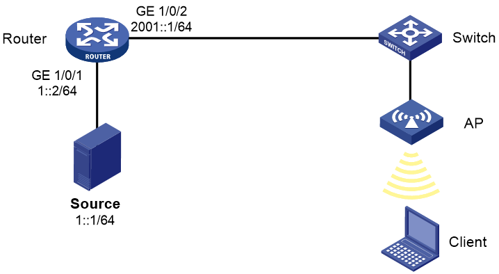
As shown in Figure 1:
· The source sends IPv6 multicast traffic to IPv6 multicast group FF1E::1.
· The client is a receiver host of the IPv6 multicast group.
· The source and the client can reach each other.
Configure Layer 2 IPv6 multicast on the fat AP so that the client can receive the IPv6 multicast traffic from the source.
Analysis
To implement Layer 2 IPv6 multicast, enable MLD snooping globally and in the VLAN to which the client belongs.
Restrictions and guidelines
Make sure the devices on the network can reach each other.
Procedures
Configuring the router
# Enable IP multicast routing.
<Router> system-view
[Router] ipv6 multicast routing
[Router-mrib] quit
# Enable IPv6 PIM-DM on GigabitEthernet 1/0/1.
[Router] interface gigabitethernet 1/0/1
[Router-GigabitEthernet1/0/1] pim ipv6 dm
[Router-GigabitEthernet1/0/1] quit
# Enable MLD on GigabitEthernet 1/0/2.
[Router] interface gigabitethernet 1/0/2
[Router-GigabitEthernet1/0/2] mld enable
[Router-GigabitEthernet1/0/2] quit
Configuring the AP
1. Configure wireless services:
# Create VLAN 100.
<AP> system-view
[AP] Vlan 100
[AP-vlan100] quit
# Create service template 1 and enter its view.
[AP] wlan service-template 1
# Configure the SSID as service.
[AP-wlan-st-1] ssid service
# Specify VLAN 100 for clients to access the WLAN defined by the service template.
[AP-wlan-st-1] vlan 100
# Enable the service template.
[AP-wlan-st-1] service-template enable
[AP-wlan-st-1] quit
# Bind the service template to interface WLAN-Radio 1/0/1.
[AP] interface WLAN-Radio 1/0/1
[AP-WLAN-Radio1/0/1] service-template 1
[AP-WLAN-Radio1/0/1] quit
2. Configure MLD snooping:
# Enable MLD snooping globally.
[AP] mld-snooping
[AP-mld-snooping] quit
# Enable MLD snooping on VLAN 100.
[AP] vlan 100
[AP-vlan100] mld-snooping enable
[AP-vlan100] quit
3. Configure GigabitEthernet 1/0/1 on the AP as a trunk port, and assign the port to VLAN 100.
[AP] interface GigabitEthernet 1/0/1
[AP-GigabitEthernet1/0/1] port link-type trunk
[AP-GigabitEthernet1/0/1] port trunk permit vlan 100
[AP-GigabitEthernet1/0/1] quit
4. Configure the client to access the WLAN service with the SSID service and request multicast traffic for IPv6 multicast group FF1E::1. (Details not shown.)
Verifying the configuration
# Display detailed information about dynamic MLD snooping group entries for VLAN 100 on the AP.
[AP]display mld-snooping group vlan 100 verbose
Total 1 entries.
VLAN 100: Total 1 entries.
(::,FF1E::101)
Attribute: local port
FSM information: normal
Host slots (0 in total):
Host ports (1 in total):
WLAN-BSS1/0/20 (00:03:23)
The output shows that WLAN-BSS 1/0/20 on the AP has joined the IPv6 multicast group FF1E::1.
Configuration files
· Router:
#
ipv6 multicast routing
#
interface gigabitethernet 1/0/1
pim ipv6 dm
#
interface gigabitethernet 1/0/2
mld enable
#
· AP:
#
vlan 100
#
wlan service-template 1
ssid service
vlan 100
service-template enable
#
interface WLAN-Radio 1/0/1
service-template 1
#
mld-snooping
#
vlan 100
mld-snooping enable
#
interface GigabitEthernet 1/0/1
port link-type trunk
port trunk permit vlan 100
#
Related documentation
· Network Connectivity Command Reference in H3C Access Points Command References
· Network Connectivity Configuration Guide in H3C Access Points Configuration Guides
· WLAN Access Command Reference in H3C Access Points Command References
· WLAN Access Configuration Guide in H3C Access Points Configuration Guides
