- Table of Contents
-
- 04-CLI configuration examples (AP standalone)
- 01-WPA2-PSK Encryption Configuration Examples
- 02-Client Rate Limiting Configuration Examples
- 03-NAT Configuration Examples
- 04-PPPoE Configuration Examples
- 05-Mesh WDS Configuration Examples
- 06-Local MAC Authentication (IPv6) Configuration Examples
- 07-IPv6 Configuration Examples
- 08-Layer 2 IPv6 Multicast Configuration Examples
- 09-Interoperation of Fat APs and Switch for WLAN Access and Roaming Configuration Examples
- 10-Remote 802.1X Authentication Configuration Examples
- 11-Remote MAC Authentication Configuration Examples
- 12-Anchor AC Mode Local Forwarding Configuration Examples
- 13-Anchor AC Mode Dual-Link Backup Configuration Examples
- 14-Anchor AC Mode Internal-to-External Access Through NAT Configuration Examples
- 15-Anchor AC Mode Remote Portal Auth in Local Forwarding Configuration Examples
- 16-Anchor AC Mode Remote Portal Auth in Centralized Forwarding Configuration Examples
- 17-Anchor AC Mode Remote 802.1X Auth in Local Forwarding Configuration Examples
- 18-Anchor AC Mode Remote 802.1X Auth in Centralized Forwarding Configuration Examples
- 19-Anchor AC Mode Remote AP Configuration Examples
- Related Documents
-
| Title | Size | Download |
|---|---|---|
| 02-Client Rate Limiting Configuration Examples | 67.35 KB |
|
H3C Access Points |
|
Comware 7 Client Rate Limiting |
|
Configuration Examples |
Copyright © 2022 New H3C Technologies Co., Ltd. All rights reserved.
No part of this manual may be reproduced or transmitted in any form or by any means without prior written consent of New H3C Technologies Co., Ltd.
Except for the trademarks of New H3C Technologies Co., Ltd., any trademarks that may be mentioned in this document are the property of their respective owners.
The information in this document is subject to change without notice.
Introduction
The following information provides an example for configuring client rate limiting.
Prerequisites
This document applies to Comware 7-based access points. Procedures and information in the examples might be slightly different depending on the software or hardware version of the access points.
The configuration examples in this document were created and verified in a lab environment, and all the devices were started with the factory default configuration. When you are working on a live network, make sure you understand the potential impact of every command on your network.
This document assumes that you have basic knowledge of client rate limiting.
Example: Configuring client rate limiting
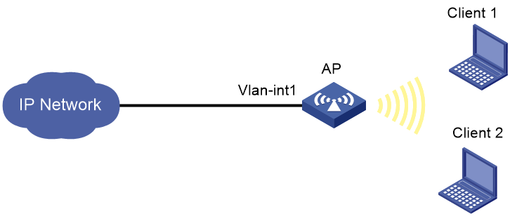
Network configuration
As shown in Figure 1, the clients access the WLAN provided by the AP. The AP obtains IP addresses from a DHCP server in the IP network.
· Configure the AP to act as a DHCP server to assign IP addresses to the clients.
· Configure client rate limit to limit the incoming traffic rate to 4000 Kbps in static mode, and limit the outgoing traffic rate to 16000 Kbps in dynamic mode.
Procedures
1. Configure AP interfaces:
# Create VLAN 100 and VLAN-interface 100, and assign an IP address to the VLAN interface. The AP will use this IP address to communicate with clients.
[AP] vlan 100
[AP-vlan100] quit
[AP] interface vlan-interface 100
[AP-Vlan-interface100] ip address 192.1.1.1 24
[AP-Vlan-interface100] quit
# Configure uplink interface VLAN-interface 1 to obtain IP addresses through DHCP.
[AP] interface vlan-interface 1
[AP-Vlan-interface1] undo ip address
[AP-Vlan-interface1] ip address dhcp-alloc
[AP-Vlan-interface1] quit
2. Configure wireless services:
# Create service template service and enter its view.
[AP] wlan service-template service
# Configure the SSID as service.
[AP-wlan-st-service] ssid service
# Specify VLAN 100 for clients to access the WLAN defined by the service template.
[AP-wlan-st-service] vlan 100
# Specify PSK as the AKM mode and specify 12345678 as the plaintext key.
[AP-wlan-st-service] akm mode psk
[AP-wlan-st-service] preshared-key pass-phrase simple 12345678
# Specify CCMP as the cipher suite and specify RSN as the security IE.
[AP-wlan-st-service] cipher-suite ccmp
[AP-wlan-st-service] security-ie rsn
# Configure rate limiting for the service template: set the CIR to 4000 Kbps for each client's incoming traffic and set the CIR to 16000 Kbps for total outgoing traffic of all clients.
[AP-wlan-st-service] client-rate-limit enable
[AP-wlan-st-service] client-rate-limit inbound mode static cir 4000
[AP-wlan-st-service] client-rate-limit outbound mode dynamic cir 16000
# Enable the service template.
[AP-wlan-st-service] service-template enable
[AP-wlan-st-service] quit
3. Bind the service template to interface WLAN-Radio 1/0/1.
[AP] interface wlan-radio 1/0/1
[AP-WLAN-Radio1/0/1] service-template service
[AP-WLAN-Radio1/0/1] quit
4. Configure the DHCP service:
# Enable DHCP.
[AP] dhcp enable
# Create a DHCP address pool named vlan100, specify subnet 192.1.1.0/24, and specify gateway address 192.1.1.1.
[AP] dhcp server ip-pool vlan100
[AP-dhcp-pool-vlan100] network 192.1.1.0 mask 255.255.255.0
[AP-dhcp-pool-vlan100] gateway-list 192.1.1.1
[AP-dhcp-pool-vlan100] quit
Verifying the configuration
# Verify that the incoming rate of each client does not exceed 4000 Kbps, and the total outgoing rate of all clients does not exceed 16000 Kbps.
Configuration files
#
dhcp enable
#
vlan 1
#
vlan 100
#
dhcp server ip-pool vlan100
gateway-list 192.1.1.1
network 192.1.1.0 mask 255.255.255.0
#
wlan service-template service
ssid service
vlan 100
akm mode psk
preshared-key pass-phrase cipher $c$3$7hZ2DNiI+h/ajPE7DhZbD6Y7py9vqf4721sp
cipher-suite ccmp
security-ie rsn
client-rate-limit enable
client-rate-limit inbound mode static cir 4000
client-rate-limit outbound mode dynamic cir 16000
service-template enable
#
interface Vlan-interface1
ip address dhcp-alloc
#
interface Vlan-interface100
ip address 192.1.1.1 255.255.255.0
#
interface WLAN-Radio1/0/1
service-template service
#
return
Related documentation
· WLAN QoS Command Reference in H3C Access Points Command References
· WLAN QoS Configuration Guide in H3C Access Points Configuration Guides
