- Table of Contents
-
- 04-CLI configuration examples (AP standalone)
- 01-WPA2-PSK Encryption Configuration Examples
- 02-Client Rate Limiting Configuration Examples
- 03-NAT Configuration Examples
- 04-PPPoE Configuration Examples
- 05-Mesh WDS Configuration Examples
- 06-Local MAC Authentication (IPv6) Configuration Examples
- 07-IPv6 Configuration Examples
- 08-Layer 2 IPv6 Multicast Configuration Examples
- 09-Interoperation of Fat APs and Switch for WLAN Access and Roaming Configuration Examples
- 10-Remote 802.1X Authentication Configuration Examples
- 11-Remote MAC Authentication Configuration Examples
- 12-Anchor AC Mode Local Forwarding Configuration Examples
- 13-Anchor AC Mode Dual-Link Backup Configuration Examples
- 14-Anchor AC Mode Internal-to-External Access Through NAT Configuration Examples
- 15-Anchor AC Mode Remote Portal Auth in Local Forwarding Configuration Examples
- 16-Anchor AC Mode Remote Portal Auth in Centralized Forwarding Configuration Examples
- 17-Anchor AC Mode Remote 802.1X Auth in Local Forwarding Configuration Examples
- 18-Anchor AC Mode Remote 802.1X Auth in Centralized Forwarding Configuration Examples
- 19-Anchor AC Mode Remote AP Configuration Examples
- Related Documents
-
| Title | Size | Download |
|---|---|---|
| 10-Remote 802.1X Authentication Configuration Examples | 1.26 MB |
|
|
|
H3C Access Points |
|
Comware 7 Remote 802.1X Authentication |
|
Configuration Examples |
|
|
Copyright © 2022 New H3C Technologies Co., Ltd. All rights reserved.
No part of this manual may be reproduced or transmitted in any form or by any means without prior written consent of New H3C Technologies Co., Ltd.
Except for the trademarks of New H3C Technologies Co., Ltd., any trademarks that may be mentioned in this document are the property of their respective owners.
The information in this document is subject to change without notice.
Contents
Example: Configuring remote 802.1X authentication for clients
Configuring the ClearPass server
Introduction
The following information provides an example to configure remote 802.1X authentication for control of access to a wireless network.
Prerequisites
The following information applies to Comware 7-based access points. Procedures and information in the examples might be slightly different depending on the software or hardware version of the access points.
The configuration examples were created and verified in a lab environment, and all the devices were started with the factory default configuration. When you are working on a live network, make sure you understand the potential impact of every command on your network.
The following information is provided based on the assumption that you have basic knowledge of 802.1X authentication, WLAN authentication, and WLAN access.
Example: Configuring remote 802.1X authentication for clients
Network configuration
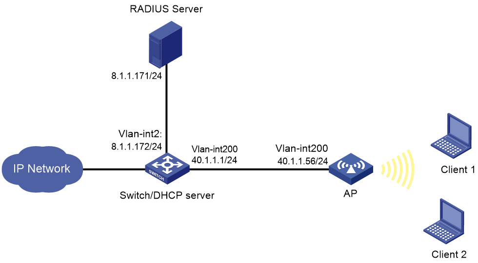
As shown in Figure 1, the clients access the WLAN through the AP. The switch acts as a DHCP server to assign IPv4 addresses to the clients. Aruba ClearPass acts as the RADIUS server.
Configure the AP, the switch, and the RADIUS server to meet the following requirements:
· The AP uses the RADIUS server to perform 802.1X authentication for wireless clients. The username and password for 802.1X authentication are both h3c1x.
· The AP uses open system authentication to provide link layer authentication for clients.
· The AP uses 802.1X AKM mode to secure data transmission between client and AP.
Procedures
Configuring the AP
1. Configure AP interfaces:
# Create VLAN 200 and VLAN-interface 200, and assign an IP address to the VLAN interface. Clients will use this VLAN to access the WLAN.
<AP> system-view
[AP] vlan 200
[AP-vlan200] quit
[AP] interface vlan-interface 200
[AP-Vlan-interface200] ip address 40.1.1.56 24
[AP-Vlan-interface200] quit
# Configure GigabitEthernet 1/0/1 (the interface connected to the switch) as a trunk, add it to VLAN 200, and set its PVID to VLAN 200.
[AP] interface gigabitethernet 1/0/1
[AP-GigabitEthernet1/0/1] port link-type trunk
[AP-GigabitEthernet1/0/1] port trunk permit vlan 200
[AP-GigabitEthernet1/0/1] port trunk pvid vlan 200
[AP-GigabitEthernet1/0/1] quit
2. Configure a static route to the RADIUS server.
[AP] ip route-static 8.1.1.0 255.255.255.0 40.1.1.1
3. Configure the 802.1X authentication method as EAP.
[AP] dot1x authentication-method eap
4. Configure a RADIUS scheme:
# Create a RADIUS scheme named radius1 and enter its view.
[AP] radius scheme radius1
# Configure the primary authentication/accounting server IP as 8.1.1.171, and set the UDP ports for authentication and accounting to 1812 and 1813, respectively.
[AP-radius-radius1] primary authentication 8.1.1.171 1812
[AP-radius-radius1] primary accounting 8.1.1.171 1813
# Configure the shared key for communication with the authentication/accounting RADIUS server as 12345678.
[AP-radius-radius1] key authentication simple 12345678
[AP-radius-radius1] key accounting simple 12345678
# Exclude the domain name from the usernames sent to the RADIUS server.
[AP-radius-radius1] user-name-format without-domain
# Configure the source IP address for outgoing RADIUS packets as 40.1.1.56.
[AP-radius-radius1] nas-ip 40.1.1.56
[AP-radius-radius1] quit
5. Configure an authentication domain that uses the RADIUS scheme for authentication, authorization, and accounting:
# Create an ISP domain named dom1 and enter its view.
[AP] domain dom1
# Use RADIUS scheme radius1 for authentication, authorization, and accounting of 802.1X authentication users.
[AP-isp-dom1] authentication lan-access radius-scheme radius1
[AP-isp-dom1] authorization lan-access radius-scheme radius1
[AP-isp-dom1] accounting lan-access radius-scheme radius1
[AP-isp-dom1] quit
6. Configure a service template:
# Create a service template named service1.
[AP] wlan service-template service1
# Configure the SSID of the service template as service.
[AP-wlan-st-service1] ssid service
# Add clients to VLAN 200 after they come online from the service template.
[AP-wlan-st-service1] vlan 200
# Configure the AKM mode as 802.1X.
[AP-wlan-st-service1] akm mode dot1x
# Set the cipher suite to CCMP and security IE to RSN.
[AP-wlan-st-service1] cipher-suite ccmp
[AP-wlan-st-service1] security-ie rsn
# Configure the user access authentication mode as 802.1X authentication.
[AP-wlan-st-service1] client-security authentication-mode dot1x
# Use ISP domain dom1 as the authentication domain for 802.1X authentication users.
[AP-wlan-st-service1] dot1x domain dom1
# Enable the service template.
[AP-wlan-st-service1] service-template enable
[AP-wlan-st-service1] quit
7. Bind the service template to interface WLAN-Radio 1/0/1.
[AP] interface WLAN-Radio 1/0/1
[AP-WLAN-Radio1/0/1] undo shutdown
[AP-WLAN-Radio1/0/1] service-template service1
[AP-WLAN-Radio1/0/1] quit
Configuring the switch
1. Configure switch interfaces:
# Create VLAN 200 and VLAN-interface 200, and assign an IP address to the VLAN interface.
<Switch> system-view
[Switch] vlan 200
[Switch-vlan200] quit
[Switch] interface vlan-interface 200
[Switch-Vlan-interface200] ip address 40.1.1.1 24
[Switch-Vlan-interface200] quit
# Create VLAN 2, which is used to connect to the RADIUS server.
[Switch] vlan 2
[Switch-vlan2] quit
# Add GigabitEthernet 1/0/2 (the interface connected to the RADIUS server) to VLAN 2.
[Switch] interface gigabitethernet 1/0/2
[Switch-GigabitEthernet1/0/2] port link-type access
[Switch-GigabitEthernet1/0/2] port access vlan 2
[Switch-GigabitEthernet1/0/2] quit
# Create VLAN-interface 2 and assign it an IP address.
[Switch] interface vlan-interface 2
[Switch-Vlan-interface2] ip address 8.1.1.172 255.255.255.0
[Switch-Vlan-interface2] quit
# Configure GigabitEthernet 1/0/1 (the interface connected to the AP) as a trunk, add it to VLAN 200, and set its PVID to VLAN 200.
[Switch] interface GigabitEthernet 1/0/1
[Switch-GigabitEthernet1/0/1] port link-type trunk
[Switch-GigabitEthernet1/0/1] port trunk permit vlan 200
[Switch-GigabitEthernet1/0/1] port trunk pvid vlan 200
[Switch-GigabitEthernet1/0/1] quit
2. Configure the DHCP service:
# Enable DHCP.
[Switch] dhcp enable
# Create a DHCP address pool named vlan200 to assign IP addresses to clients. In this pool, specify the subnet for dynamic allocation as 40.1.1.0/24, the gateway address as 40.1.1.1, the DNS server address as the gateway address (specify the actual DNS server address in your network), and forbidden IP address as 40.1.1.56.
[Switch] dhcp server ip-pool vlan200
[Switch-dhcp-pool-vlan200] network 40.1.1.0 mask 255.255.255.0
[Switch-dhcp-pool-vlan200] gateway-list 40.1.1.1
[Switch-dhcp-pool-vlan200] dns-list 40.1.1.1
[Switch-dhcp-pool-vlan200] forbidden-ip 40.1.1.56
[Switch-dhcp-pool-vlan200] quit
3. Configure the interface connected to the external network and the default route. (Details not shown.)
Configuring the ClearPass server
1. Log in to ClearPass:
# Enter the management IP address of the ClearPass server in the address bar of the Web browser to access the server Web interface. In this example, the management IP address is 8.1.1.171.
Figure 2 Logging in to ClearPass
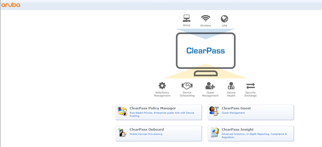
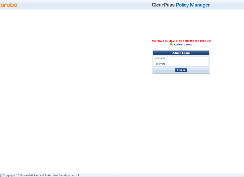
# Click ClearPass Policy Manager. Enter username admin and password 123456, and then click Log In.
Figure 3 Logging in to ClearPass Policy Manager
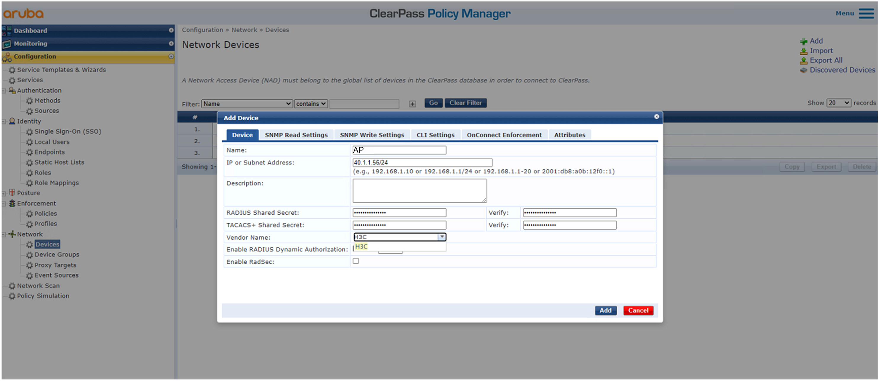
2. Add the AP to ClearPass Policy Manager:
# From the left navigation pane, select Configuration > Network > Devices. On the page that opens, click Add in the upper right corner.
a. Specify IP address 40.1.1.56/24 on the AP.
Make sure the ClearPass server can reach this IP address.
b. Configure the RADIUS shared secret.
Make sure the shared secret specified here is the same as the shared key specified for the RADIUS server on the AP. In this example, the shared secret is 12345678.
c. Select vendor name H3C.
d. Click Add.
Figure 4 Adding a device
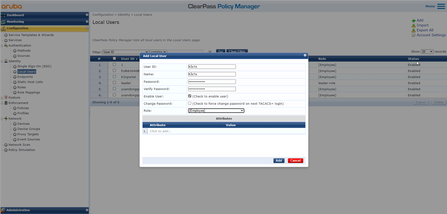
3. Add a user:
# From the left navigation pane, select Configuration > Identity > Local Users. On the page that opens, click Add in the upper right corner.
a. Set the user ID, name, and password to h3c1x.
b. Select predefined role Employee or a user-defined role. In this example, predefined role Employee is selected.
c. Click Add.
Figure 5 Adding a user
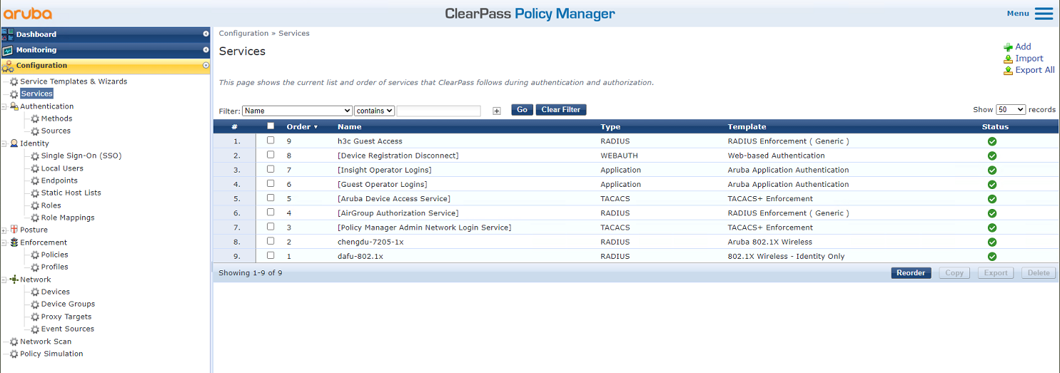
4. Add a service:
# From the left navigation pane, select Configuration > Services. On the page that opens, click Add in the upper right corner.
Figure 6 Services page
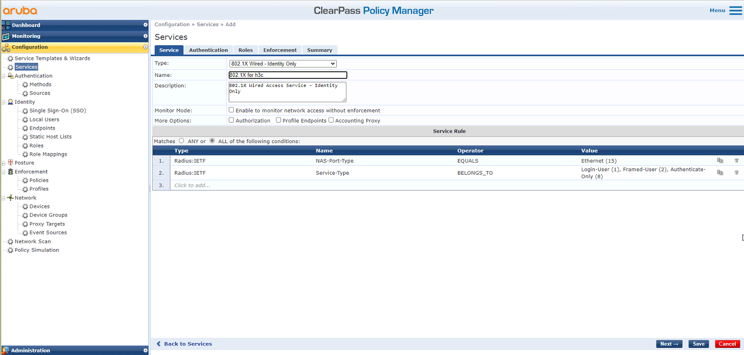
# On the Service tab, select 802.1X Wireless – Identity Only from the Type field and set the name to 802.1X for h3c.
Figure 7 Adding a service
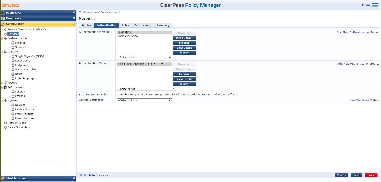
# On the Authentication tab, select [EAP MSCHAPv2] and [EAP PEAP] in the Authentication Methods field and select [Local User Repository] in the Authentication Sources field.
Figure 8 Configuring authentication
# On the Roles and Enforcement tabs, use the default settings for the parameters, and then click Save.
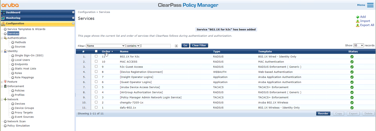
# On the Configuration > Services page, click Reorder to move the service named 802.1X for h3c to the first.
Figure 9 Reordering services
Verifying the configuration
# On the client, verify that it can be associated with service service and can pass 802.1X authentication and obtain an IP address.
# On the AP, verify that the wireless client has come online in VLAN 200.
[AP] display wlan client
Total number of clients: 1
MAC address User name R IP address VLAN
fcdb-b3d4-d88c h3c1x 1 40.1.1.2 200
Configuration files
· AP:
dot1x authentication-method eap
#
vlan 200
#
wlan service-template service1
ssid service
vlan 200
akm mode dot1x
cipher-suite ccmp
security-ie rsn
client-security authentication-mode dot1x
dot1x domain dom1
service-template enable
#
interface Vlan-interface200
ip address 40.1.1.56 255.255.255.0
#
interface GigabitEthernet1/0/1
port link-type trunk
port trunk permit vlan 1 200
port trunk pvid vlan 200
#
interface WLAN-Radio1/0/1
service-template service1
#
ip route-static 8.1.1.0 24 40.1.1.1
#
radius scheme radius1
primary authentication 8.1.1.171
primary accounting 8.1.1.171
key authentication cipher $c$3$xjh3c8fY+G24S8ncMFgLAt7nWqTjMrzBtN7P
key accounting cipher $c$3$lAOpJkHtBfyb+SiV2eVCWirmjxOZYKvo/YtT
nas-ip 40.1.1.56
#
domain dom1
authentication lan-access radius-scheme radius1
authorization lan-access radius-scheme radius1
accounting lan-access radius-scheme radius1
#
· Switch:
#
dhcp enable
#
vlan 2
#
vlan 200
#
dhcp server ip-pool vlan200
gateway-list 40.1.1.1
network 40.1.1.0 mask 255.255.255.0
dns-list 40.1.1.1
forbidden-ip 40.1.1.56
#
interface Vlan-interface2
ip address 8.1.1.172 255.255.255.0
#
interface Vlan-interface200
ip address 40.1.1.1 255.255.255.0
#
interface GigabitEthernet1/0/1
port link-mode bridge
port link-type trunk
port trunk permit vlan 1 200
port trunk pvid vlan 200
#
interface GigabitEthernet1/0/2
port link-mode bridge
port link-type access
port access vlan 2
#
Related documentation
· Network Connectivity Configuration Guide in H3C Access Points Configuration Guides
· Network Connectivity Command Reference in H3C Access Points Command References
· User Access and Authentication Configuration Guide in H3C Access Points Configuration Guides
· User Access and Authentication Command Reference in H3C Access Points Command References
· WLAN Access Configuration Guide in H3C Access Points Configuration Guides
· WLAN Access Command Reference in H3C Access Points Command References
