- Table of Contents
-
- 04-CLI configuration examples (AP standalone)
- 01-WPA2-PSK Encryption Configuration Examples
- 02-Client Rate Limiting Configuration Examples
- 03-NAT Configuration Examples
- 04-PPPoE Configuration Examples
- 05-Mesh WDS Configuration Examples
- 06-Local MAC Authentication (IPv6) Configuration Examples
- 07-IPv6 Configuration Examples
- 08-Layer 2 IPv6 Multicast Configuration Examples
- 09-Interoperation of Fat APs and Switch for WLAN Access and Roaming Configuration Examples
- 10-Remote 802.1X Authentication Configuration Examples
- 11-Remote MAC Authentication Configuration Examples
- 12-Anchor AC Mode Local Forwarding Configuration Examples
- 13-Anchor AC Mode Dual-Link Backup Configuration Examples
- 14-Anchor AC Mode Internal-to-External Access Through NAT Configuration Examples
- 15-Anchor AC Mode Remote Portal Auth in Local Forwarding Configuration Examples
- 16-Anchor AC Mode Remote Portal Auth in Centralized Forwarding Configuration Examples
- 17-Anchor AC Mode Remote 802.1X Auth in Local Forwarding Configuration Examples
- 18-Anchor AC Mode Remote 802.1X Auth in Centralized Forwarding Configuration Examples
- 19-Anchor AC Mode Remote AP Configuration Examples
- Related Documents
-
| Title | Size | Download |
|---|---|---|
| 09-Interoperation of Fat APs and Switch for WLAN Access and Roaming Configuration Examples | 88.16 KB |
|
H3C Access Points |
|
Comware 7 Interoperation of Fat APs and Switches for WLAN Access and Roaming |
|
Configuration Examples |
Copyright © 2022 New H3C Technologies Co., Ltd. All rights reserved.
No part of this manual may be reproduced or transmitted in any form or by any means without prior written consent of New H3C Technologies Co., Ltd.
Except for the trademarks of New H3C Technologies Co., Ltd., any trademarks that may be mentioned in this document are the property of their respective owners.
The information in this document is subject to change without notice.
Introduction
The following information provides an example for configuring a WLAN with multiple fat APs switches.
Prerequisites
This document applies to Comware 7-based access points. Procedures and information in the examples might be slightly different depending on the software or hardware version of the access points.
The configuration examples in this document were created and verified in a lab environment, and all the devices were started with the factory default configuration. When you are working on a live network, make sure you understand the potential impact of every command on your network.
This document assumes that you have basic knowledge of WLAN access and WLAN roaming.
Example: Configuring WLAN with multiple fat APs and switches
Network configuration
As shown in Figure 1, the WLAN includes H3C Wi-Fi 6 wireless access points, PoE switch, and Layer 3 switch. Make sure the network configuration meets the following requirements:
· The Layer 3 switch acts as a DHCP server to assign IP addresses to clients.
· The Layer 2 switch supplies power to APs in PoE mode.
· The clients access the WLAN over VLAN 100.
· The IP addresses of APs are manually assigned.
· The client can roam from one radio to another radio within a fat AP or roam from one fat AP to another fat AP.
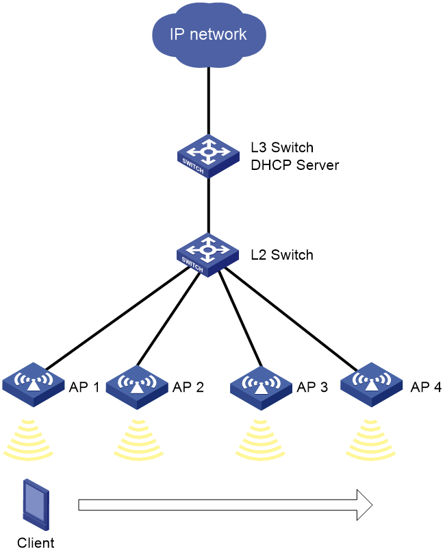
Table 1 IP address planning and VLAN planning
|
Device |
Interface |
IP address |
|
L3 switch |
10.100.2.111/16 |
|
|
L2 switch |
VLAN-interface 100 |
10.100.2.112/16 |
|
AP 1 |
VLAN-interface 100 |
10.100.2.121/16 |
|
AP 2 |
VLAN-interface 100 |
|
|
AP 3 |
VLAN-interface 100 |
10.100.2.123/16 |
|
AP 4 |
VLAN-interface 100 |
10.100.2.124/16 |
Analysis
· To ensure successful communication, configure Layer 2 connectivity between fat APs and the Layer 2 switch.
· For dynamic IP address assignment to clients, enable the DHCP server feature on the Layer 3 switch.
· Enable PoE power supply on the Layer 2 switch to supply power for fat APs.
· Configure a valid region code for each fat AP.
· Configure a fat AP mobility group for inter-AP roaming.
Procedures
Configuring the Layer 3 switch
1. Configure interface settings:
# Create VLAN 100 and VLAN-interface 100, and assign an IP address to the VLAN interface.
[L3 switch] vlan 100
[L3 switch-vlan100] quit
[L3 switch] interface vlan-interface 100
[L3 switch-Vlan-interface1] ip address 10.100.2.111 255.255.0.0
[L3 switch-Vlan-interface1] quit
# Configure the interface that is connected to the Layer 2 switch as a trunk port, and assign the port to VLAN 100. In this example, the interface is GigabitEthernet 1/0/2.
[L3 switch] interface gigabitethernet 1/0/2
[L3 switch-GigabitEthernet1/0/2] port link-type trunk
[L3 switch-GigabitEthernet1/0/2] port trunk permit vlan 100
[L3 switch-GigabitEthernet1/0/2] quit
2. Configure DHCP server settings:
# Create DHCP address pool 100 for dynamic address assignment to clients. Specify subnet 10.100.2.0/16 for the pool and exclude IP address 10.100.2.112 and IP range 10.100.2.121 to 10.100.2.124 from dynamic allocation. Set the gateway IP address to 10.100.2.111.
[L3 switch] dhcp server ip-pool 100
[L3 switch-dhcp-pool-100] network 10.100.2.0 mask 255.255.0.0
[L3 switch-dhcp-pool-100] gateway-list 10.100.2.111
[L3 switch-dhcp-pool-100] forbidden-ip 10.100.2.112
[L3 switch-dhcp-pool-100] forbidden-ip-range 10.100.2.121 10.100.2.124
[L3 switch-dhcp-pool-100] quit
# Enable the DHCP server feature.
[L3 switch] dhcp enable
Configuring the Layer 2 switch
# Create VLAN 100 and VLAN-interface 100, and assign an IP address to the VLAN interface.
<L2 switch> system-view
[L2 switch] interface vlan-interface 100
[L2 switch-Vlan-interface100] ip address 10.100.2.112 255.255.0.0
[L2 switch-Vlan-interface100] quit
[L2 switch] vlan 100
[L2 switch-vlan100] quit
# Configure the interface that is connected to the Layer 3 switch as a trunk port, and assign the port to VLAN 100. In this example, the interface is GigabitEthernet 1/0/1.
[L2 switch] interface gigabitethernet 1/0/1
[L2 switch-GigabitEthernet1/0/1] port link-type trunk
[L2 switch-GigabitEthernet1/0/1] port trunk permit vlan 100
[L2 switch-GigabitEthernet1/0/1] quit
# Configure the interface that is connected to a FAT AP as an access port, assign the port to VLAN 100, and then enable PoE power supply. In this example, the interface is GigabitEthernet 1/0/2.
[L2 switch] interface range gigabitethernet 1/0/2
[L2 switch-GigabitEthernet1/0/2] port access vlan 100
[L2 switch-GigabitEthernet1/0/2] poe enable
[L2 switch-GigabitEthernet1/0/2] quit
Configuring fat APs
|
|
NOTE: The fat AP configuration takes fat AP 1 as an example. You can configure fat APs 2, 3, and 4 in the same way as you configure fat AP 1. |
1. Specify a region code for fat AP 1. If the default region code of fat AP 1 is the same as the example region code, skip this step.
<AP> system-view
[AP] wlan global-configuration
[AP-wlan-global-configuration] region-code JP
This operation may reset the radio parameters. Continue? [Y/N]:y
[AP-wlan-global-configuration] quit
2. Configure interface settings for fat AP 1:
# Create VLAN 100 and VLAN-interface 100, and assign an IP address to the VLAN interface.
[AP] interface vlan-interface 100
[AP-Vlan-interface100] ip address 10.100.2.121 255.255.0.0
[AP-Vlan-interface100] quit
[AP] vlan 100
[AP-vlan100] quit
# Configure the interface that is connected to the Layer 2 switch as an access port, and assign the port to VLAN 100. In this example, the interface is GigabitEthernet 1/0/1.
[AP] interface gigabitethernet 1/0/1
[AP-GigabitEthernet1/0/1] port link-type access
[AP-GigabitEthernet1/0/1] port access vlan 100
[AP-GigabitEthernet1/0/1] quit
3. Configure service template settings for fat AP 1:
# Create service template service1 and enter its view.
[AP] wlan service-template service1
# Configure the SSID as service.
[AP-wlan-st-service1] ssid service
# Assign the clients that come online through service template service1 to VLAN 100.
[AP-wlan-st-service1] vlan 100
# Specify PSK as the AKM mode and specify 12345678 as the plaintext key.
[AP-wlan-st-service1] akm mode psk
[AP-wlan-st-service1] preshared-key pass-phrase simple 12345678
# Specify CCMP as the cipher suite and specify RSN as the security IE.
[AP-wlan-st-service1] cipher-suite ccmp
[AP-wlan-st-service1] security-ie rsn
# Enable service template service1.
[AP-wlan-st-service1] service-template enable
[AP-wlan-st-service1] quit
# Bind service template service1 to interface WLAN-Radio 1/0/1.
[AP] interface wlan-radio 1/0/1
[AP-WLAN-Radio1/0/1] undo shutdown
[AP-WLAN-Radio1/0/1] service-template service1
[AP-WLAN-Radio1/0/1] quit
# Bind service template service1 to interface WLAN-Radio 1/0/2.
[AP] interface wlan-radio 1/0/2
[AP-WLAN-Radio1/0/2] undo shutdown
[AP-WLAN-Radio1/0/2] service-template service1
[AP-WLAN-Radio1/0/2] quit
4. Configure mobility group settings for fat AP 1:
# Create mobility group office.
[AP] wlan mobility group office
# Set the IP address type to IPv4 for IADTP tunnels.
[AP-wlan-mg-office] tunnel-type ipv4
# Set the source IP address for IACTP tunnel establishment to the IP address of fat AP 1. In this example, the IP address of fat AP 1 is 10.100.2.121. Fat AP 1 uses the specified source IP address for IACTP tunnel establishment when it is added to mobility group office.
[AP-wlan-mg-office] source ip 10.100.2.121
# Enable automatic group member discovery.
[AP-wlan-mg-office] member auto-discovery
# Enable mobility group office.
[AP-wlan-mg-office] group enable
[AP-wlan-mg-office] quit
Verifying the configuration
After the client roam from AP 1 to AP 2, use commands to view the following roaming information:
# Display mobility group information to verify mobility group office has been created on AP 1.
[AP1] display wlan mobility group
Mobility group name: office
Tunnel type: IPv4
Source IPv4: 10.100.2.121
Source IPv6: Not configured
Authentication method: Not configured
Mobility group status: Enabled
Member entries: 1
IP address State Online time
10.100.2.122 Up 00hr 00min 12sec
10.100.2.123 Up 00hr 00min 15sec
10.100.2.124 Up 00hr 00min 20sec
# Display mobility group information to verify mobility group office has been created on AP 2.
[AP2] display wlan mobility group
Mobility group name: office
Tunnel type: IPv4
Source IPv4: 10.100.2.122
Source IPv6: Not configured
Authentication method: Not configured
Mobility group status: Enabled
Member entries: 1
IP address State Online time
10.100.2.121 Up 00hr 00min 05sec
10.100.2.123 Up 00hr 00min 15sec
10.100.2.124 Up 00hr 00min 20sec
# Display client roaming information on AP 1 to verify that the client came online from AP 1 and roamed to AP 2. You can use the display wlan mobility roam-track mac-address command to display client roaming information.
[AP1] display wlan mobility roam-track mac-address bce2-659a-3232
Total entries : 2
Current entries: 2
BSSID Created at Online time AP IP address RID AP name
74ea-c8fd-c200 2016-06-14 11:12:28 00hr 06min 56sec 10.100.2.122 2 ap2
74ea-c8fd-c1e0 2016-06-14 11:11:28 00hr 03min 30sec 127.0.0.1 1 ap1
# On AP 1, verify that the client has roamed to AP 2. You can use the display wlan mobility roam-out command to display information about the clients that have roamed from AP 1.
[AP1] display wlan mobility roam-out
Total entries: 1
MAC address BSSID VLAN ID Online time FA IP address
bce2-659a-3232 74ea-c8fd-c200 1 00hr 01min 59sec 10.100.2.122
# On AP 2, verify that the client has associated with AP 2, and the roaming status is Inter-AP Roam. You can use the display wlan client command to display information about the clients associated with AP 2.
[AP2] display wlan client verbose
Total number of clients: 1
MAC address : bce2-659a-3232
IPv4 address : 10.100.2.125
IPv6 address : N/A
Username : N/A
AID : 978
Radio ID : 2
Channel : 36
SSID : service
BSSID : 74ea-c8fd-c200
VLAN ID : 100
VLAN ID2 : N/A
Sleep count : 49
……
Roam status : Inter-AP roam
Key derivation : N/A
PMF status : N/A
Forwarding policy name : Not configured
Online time : 0days 0hours 0minutes 54seconds
FT status : Inactive
# On AP 2, verify that the client has roamed to AP 2. You can use the display wlan mobility roam-in command to display information about the clients that have roamed to AP 2.
[AP2] display wlan mobility roam-in
Total entries: 1
MAC address BSSID VLAN ID HA IP address
bce2-659a-3232 74ea-c8fd-c200 100 10.100.2.121
Configuration files
#
vlan 100
#
interface Vlan-interface100
ip address 10.100.2.111 255.255.0.0
#
interface GigabitEthernet1/0/2
port link-type trunk
port trunk permit vlan 100
#
dhcp server ip-pool vlan100
gateway-list 10.100.2.111
network 10.100.2.0 mask 255.255.0.0
forbidden-ip 10.100.2.112
forbidden-ip range 10.100.2.121 10.100.2.124
dhcp enable
· L2 Switch
#
vlan 100
#
interface Vlan-interface100
ip address 10.100.2.112 255.255.0.0
#
interface GigabitEthernet1/0/1
port link-type trunk
port trunk permit vlan 100
#
interface GigabitEthernet1/0/2
port link-type access
port access vlan 100
poe enable
· FAT AP 1
#
vlan 100
#
interface Vlan-interface100
ip address 10.100.2.121 255.255.0.0
#
interface GigabitEthernet1/0/1
port link-type access
port access vlan 100
#
wlan service-template service1
ssid service
vlan 100
akm mode psk
preshared-key pass-phrase simple 12345678
cipher-suite ccmp
security-ie rsn
service-template enable
#
interface WLAN-Radio1/0/1
undo shutdown
service-template service1
#
interface WLAN-Radio1/0/2
undo shutdown
service-template service1
#
wlan mobility group office
tunnel-type ipv4
source ip 10.100.2.121
member auto-discovery
group enable
Related documentation
· Network Connectivity Command Reference in H3C Access Points Cloud Mode Command References
· Network Connectivity Configuration Guide in H3C Access Points Cloud Mode Configuration Guides
· WLAN Access Command Reference in H3C Access Points Cloud Mode Command References
· WLAN Access Configuration Guide in H3C Access Points Cloud Mode Configuration Guides
· WLAN Roaming Command Reference in H3C Access Points Cloud Mode Command References
· WLAN Roaming Configuration Guide in H3C Access Points Cloud Mode Configuration Guides
