- Table of Contents
-
- H3C S7500E Switch Series Installation Guide-6W108
- 00-Preface
- 01-Chapter 1 Preparing for Installation
- 02-Chapter 2 Installing the Switch
- 03-Chapter 3 Installing FRUs
- 04-Chapter 4 Connecting Your Switch to the Network
- 05-Chapter 5 Replacement Procedures
- 06-Chapter 6 Troubleshooting
- 07-Appendix A Chassis Views and Technical Specifications
- 08-Appendix B FRUs and Compatibility Matrixes
- 09-Appendix C LEDs
- 10-Appendix D Cables
- 11-Appendix E Engineering Labels for Cables
- 12-Appendix F Cable Management
- Related Documents
-
| Title | Size | Download |
|---|---|---|
| 11-Appendix E Engineering Labels for Cables | 313.61 KB |
11 Appendix E Engineering labels
Affixing a label to a signal cable
Affixing a label to a power cord
Engineering labels for network cables
Engineering labels for optical fibers
Engineering labels for DC power cords
Engineering labels for AC power cords
Engineering labels for devices
11 Appendix E Engineering labels
Engineering labels are used to identify cables and devices for easy maintenance after installation.
There are two types of engineering labels, labels for cables and labels for devices.
Labels for cables
Cables include signal cables such as network cables and fibers, and power cords such as AC power cords and DC power cords. Labels for cables include labels for signal cables, labels for power cords, and generic labels.
Labels for signal cables
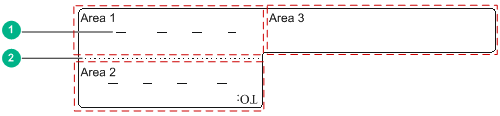
A label for signal cables is L-shaped with fixed dimensions. The light-blue dividing lines on the label help to specify more clearly the position of the cable. For example, there is one dividing line between the rack number and the chassis number and another one between the chassis number and the slot number. The cut dotted line helps to fold the label when you affix it to the cable. A mark "TO:" is located at the lower right corner of the label to identify the peer end of the cable on which the label is affixed.
As shown in Figure 11-1, write a signal cable label as follows:
· Write the position of the cable in Area 1.
· Write the position of the cable on the peer end in Area 2.
· Area 3 is the part that is folded up inside the label when the label is affixed to the cable.
Figure 11-1 Label for signal cables
|
(1) Dividing line |
(2) Cut dotted line |
Labels for power cords
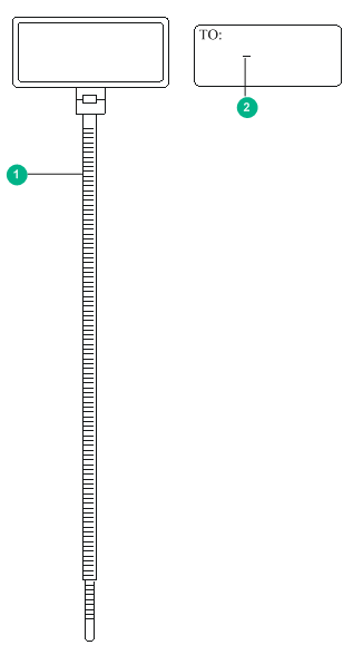
A label for power cords should be attached to the identification plate on a cable tie that binds the power cords. The identification plate has an embossment of 0.2 × 0.6 mm (0.008 × 0.02 in) around (symmetric on both sides), and the area in the middle is for affixing the label.
A mark "TO:" is located at the upper left corner of the label to identify the peer end of the cord on which the label is affixed. You can write the position of the peer device, control cabinet, distribution box, or power socket. The meaning of the dividing lines is the same as labels for signal cables.
Figure 11-2 Label for power cords
|
(1) Cable tie |
(2) Dividing line on the label |
Generic labels
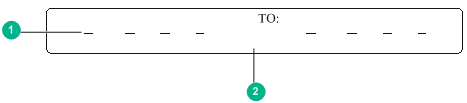
A generic label is bar-shaped with fixed dimensions. It is applicable to both signal cables and power cords. A mark "TO:" is located at the upper left corner in the right area of the label to identify the peer end of the cable on which the label is affixed. The meaning of the dividing lines is the same as labels for signal cables.
Figure 11-3 Generic label
|
(1) Dividing line on the label |
(2) Cut dotted line |
Labels for devices
A device label is used to identify the device name, model, address, installation date, and so on.
Filling in labels
You can print or write desired contents on labels. As a best practice, print labels.
To print labels, select a label printer and a proper label template as needed. For more information about using a label printer, see the user guide of the printer.
To write labels, use black markers. A marker has two nibs. Be sure to use the smaller nib to write labels.
Affixing labels
After printing or writing a label, remove the label from the bottom page and affix it to the signal cable, or the identification plate of the power cord.
Affixing a label to a signal cable
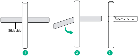
Typically, a label is affixed 2 cm (0.79 in) away from the connector on a signal cable. You can affix the label to other positions as needed. Figure 11-4 shows how to affix a label when a cable is laid vertically.
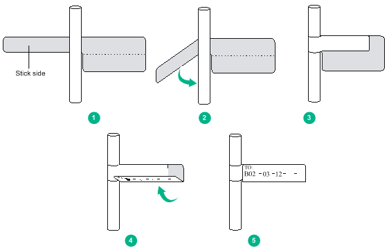
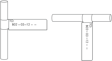
Figure 11-5 shows the affixed labels when the cable is laid vertically and horizontally.
Figure 11-5 Affixed labels
Affixing a label to a power cord
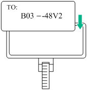
Stick the label to the recessed rectangular area on the identification plate. You can stick the label to either side of the identification plate. Be sure to affix the labels on the same side of the identification plates.
A cable tie is bundled 2 cm (0.79 in) away from the connector. You can affix the label to other positions as needed. Figure 11-4 shows how to affix a label when a cable is laid horizontally.
Figure 11-6 Affixing a label
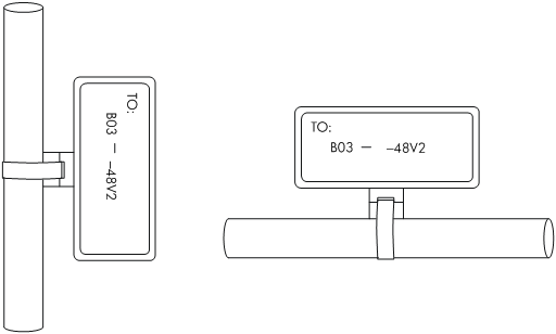
Bind cable ties on both ends of a cable. After the bundling, the finished identification plate should be on top of the cable in horizontal cabling, or on the right side of the cable in vertical cabling. Make sure the label is facing out, as shown in Figure 11-7.
Affixing a generic label
The requirements for affixing a generic label are the same as affixing a label on a signal cable. For more information, see "Affixing a label to a signal cable." For the example of affixed labels, see Figure 11-5.
Figure 11-8 Affixing a generic label
Affixing a label to a device
Remove the device label and stick it to the device. You can stick a device label to any desired position on the device.
Guidelines
· When you print, write, or affix labels, keep the labels clean.
· Do not use ink-jet printers and ink pens.
· Affix labels with good order in alignment.
· Avoid cable bents or other positions that might affect cable installation when you stick a label or bundle a cable tie with a power cord identification plate.
· Bundle cable ties at the same positions of power cords, with identification plates on the same side.
· The positions of "up", "down", "right" or "left" are all based on the viewpoint of the engineering person who is working on the label.
Examples
The label examples in this document are for reference only.
Engineering labels for network cables
These labels are affixed to Ethernet cables that connect cards in a chassis.
Table 11-1 Information on a label affixed to an Ethernet cable
|
Content |
Meaning |
Example |
|
MN-B-C-D |
MN—Rack number |
· M—Row number of the rack in the equipment room, in the range of A to Z. · N—Column number of the rack in the equipment room, in the range of 01 to 99. For example, A01. |
|
B—Chassis number |
Numbered in top-down order with two digits, for example, 01. |
|
|
C—Slot number |
Numbered in top-down and left-right order with two digits, for example, 01. |
|
|
D—Ethernet port number |
Numbered in top-down and left-right order with two digits, for example, 01. |
|
|
MN-Z |
MN—Rack number |
· M—Row number of the rack in the equipment room, in the range of A to Z. · N—Column number of the rack in the equipment room, in the range of 01 to 99. For example, B02. |
|
Z—Location number |
Location number of the terminal or device onsite. If you connect the cable to a switch in a rack, specify the rack number, chassis number, and Ethernet port number, for example, B02-03-12. If you connect the cable to a terminal or an NMS, specify the location number of the terminal or the NMS. |
The information provided on the following labels is different, subject to different devices that the Ethernet cables are connecting. For example:
· On a label for the Ethernet cable that connects a switch and a server:
¡ For the switch end—Rack number, chassis number, and Ethernet port number on the switch.
¡ For the server end—Rack number and chassis number, or the specific location of the server if the server is laid separately.
· On a label for the Ethernet cable that connects the switch and a terminal:
¡ For the switch end—Rack number, chassis number, and Ethernet port number, or the specific location of the switch if the switch is laid separately. The definitions of the rack number and chassis number are the same as those described in Table 11-1.
¡ For the terminal end—Ethernet port number of the terminal.
Figure 11-9 Example of a label on an Ethernet cable
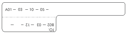
· A01-03-10-05—The local end of the Ethernet cable is connected to Ethernet Port 05, Slot 10, Chassis 03 of the rack on Row A, Column 01 in the equipment room.
· B02-03-12—The peer end of the Ethernet cable is connected to Ethernet Port 12, Chassis 03 of the rack on Row B, Column 02 in the equipment room.
Engineering labels for optical fibers
These labels are affixed to optical fibers that connect the fiber ports on the cards in a chassis, or connect fiber ports on box-type devices. The following two types of labels are used for optical fibers:
· Labels for a fiber that connects the fiber ports on two devices
Table 11-2 Information on labels affixed to the fiber between two devices
|
Content |
Meaning |
Example |
|
MN-B-C-D-R/T |
MN—Rack number |
· M—Row number of the rack in the equipment room, in the range of A to Z. · N—Column number of the rack in the equipment room, in the range of 01 to 99. For example, A01. |
|
B—Chassis number |
Numbered in top-down order with two digits, for example, 01 |
|
|
C—Slot number |
Numbered in top-down and left-right order with two digits, for example, 01. |
|
|
D—Fiber port number |
Numbered in top-down and left-right order with two digits, for example, 05. |
|
|
R—Optical receiving interface T—Optical transmitting interface |
N/A |
|
|
MN-B-C-D-R/T |
MN—Rack number |
The meanings are the same as above. If the local device and the peer device are not in the same equipment room, MN can be the name of the equipment room. |
|
B—Chassis number |
||
|
C—Slot number |
||
|
D—Fiber port number |
||
|
R—Optical receiving interface T—Optical transmitting interface |
N/A |
Figure 11-10 Example of a label on an optical fiber between two devices
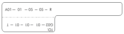
¡ A01-01-05-05-R—The local end of the optical fiber is connected to Optical Receiving Interface 05 on Slot 5, Chassis 01 in the rack on Row A, Column 01 in the equipment room.
¡ G01-01-01-01-T—The peer end of the optical fiber is connected to Optical Transmitting Interface 01 on Slot 01, Chassis 01 in the rack on Row G, Column 01 in the equipment room
· Labels for a fiber that connects the device and the optical distribution frame (ODF)
Table 11-3 Information on labels affixed to the fiber between the device and the ODF
|
Content |
Meaning |
Example |
|
MN-B-C-D-R/T |
MN—Rack number |
· M—Row number of the rack in the equipment room, in the range of A to Z. · N—Column number of the rack in the equipment room, in the range of 01 to 99. For example, A01. |
|
B—Chassis number |
Numbered in bottom-up order with two digits, for example, 01. |
|
|
C—Slot number |
Numbered in top-down and left-right order with two digits, for example, 01. |
|
|
D—Fiber port number |
Numbered in top-down and left-right order with two digits, for example, 05. |
|
|
R—Optical receiving interface T—Optical transmitting interface |
N/A |
|
|
ODF-MN-B-C-R/T |
MN—Row number and column number of ODF |
· M—Row number of the rack in the equipment room, in the range of A to Z. · N—Column number of the rack in the equipment room, in the range of 01 to 99. For example, G01 is the ODF of Row G and Column 01. |
|
B—Row number of the terminal device |
In the range of 01 to 99, for example, 01-01. |
|
|
C—Column number of the terminal device |
||
|
R—Optical receiving interface T—Optical transmitting interface |
N/A |
Figure 11-11 Example of a label on an optical fiber between the device and the ODF
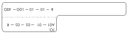
¡ ODF-G01-01-01-R—The local end of the optical fiber is connected to the optical receiving terminal on Row 01, Column 01 of the ODF in Row G Column 01 in the equipment room.
¡ A01-01-05-05-R—The peer end of the optical fiber is connected to Optical Receiving Interface 5 on Slot 05, Chassis 01 in the cabinet on Row A, Column 01 in the equipment room.
Engineering labels for DC power cords
These labels are affixed to DC cords that provide power for racks, and the protection grounding cables including the –48V, PGND, and BGND cables. The labels for DC power cords are affixed to one side of the identification plates on cable ties.
Table 11-4 Information on labels affixed to DC power cords
|
Content |
Meaning |
|
MN(BC)-–48Vn |
· Loaded cabinet side—Only MN is used to identify the cabinet number (row number and column number in the equipment room). · Power cabinet side—MN identifies the row and column number of the power distribution equipment like the control cabinet and distribution box. BC identifies the row and column number of the –48V connector (if there is no row number or column number, or the connector can be identified without them, BC can be omitted). RTN and PGND have no row and column number for identification. · n—Power port number in down-top and left-right order, in the range of 1 to 3. |
|
MN(BC)-RTN |
|
|
MN(BC)-PGND |
The label only carries location information about the peer equipment, control cabinet, or distribution box, while the information of the local end is not necessary. Table 11-4 lists the information of two –48V power supplies on the label. The information for other DC voltages (such as 24V, 60V) should be given in similar methods.
Make sure labels are affixed in the correct direction. After the cable ties are bundled onto the cable, the identification plates with the labels should face up. The text on the labels in the same cabinet should be in the same direction, as shown in Figure 11-12.
Figure 11-12 Example of labels on a DC power cord
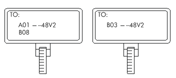
· A01/B08––48V2 (loaded cabinet side)—The power cord is –48V2 DC supply, which is from the 8th connecter on the second row of –48V bus bar in the cabinet on Row A, and Column 1 in the equipment room.
· B03––48V2 (distribution box side)—The power cord is –48V2 DC supply, which is from the loaded cabinet on Row B, Column 03 in the equipment room.
In the power distribution box (or the first power cabinet of a row in the transmission equipment room), every terminal block on the –48V connector bar has a numeric identification. For example, in the above label of "A01/B08--48V2", "08" (or sometimes "8") is the numeric identification of the terminal block.
PGND and RTN are two copper bars, on which the terminal blocks are short-circuited, so which terminal is connected makes no difference. You only need to give the row and column numbers of the power distribution box, instead of giving the specific serial number of the terminal block on the copper bar. For example, if the label on the loaded cabinet side is "A01-RTN", it means that the power cord is an RTN that connects RTN copper bar in the power distribution box on Row A, Column 01 in the equipment room. Information on the labels for PGND cables should be given in the similar way.
Engineering labels for AC power cords
These labels are affixed to the AC cords that provide power for cabinets and protection grounding cables, including POWER, RTN, and PGND cables. The 220 VAC cables and related PGND and RTN cables are covered with insulating sheath, so the labels only need to contain "AC" and the cabinet number. The labels for AC power cords are affixed to one side of the identification plates on cable ties.
Table 11-5 Information on labels affixed to AC power cords
|
Content |
Meaning |
|
MN-AC |
MN: Rack number (row number and column number in the equipment room) or the location of the socket where the power is led in. The location of the socket is marked according to onsite situation. If the sockets can be identified by row number and column number, they can be numbered following the same rule for the rack number. Otherwise, specify the detailed locations to avoid confusing with other sockets. |
The label only carries location information about the peer equipment and the power socket, while information of the local end is not necessary. Make sure labels are affixed in the correct direction. That is, after the cable ties are bundled onto the cable, the identification plates with the labels should face up, and the text on the labels in the same cabinet must be in the same direction, as shown in Figure 11-13:
Figure 11-13 Example of labels on an AC power cord
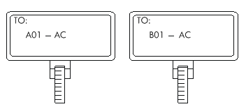
· A01-AC (loaded cabinet side)—The power cord is connected to the socket of Row A and Column 01 in the equipment room.
· B01-AC (power socket side)—The power cord is connected to the loaded cabinet of Row B, Column 01 in the equipment room.
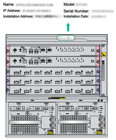
Engineering labels for devices
These labels can be affixed to any device.
You can fill in the device name, model, IP address, serial number, installation address, and installation date on a device label.
Figure 11-14 Example of a device label