- Table of Contents
-
- H3C S7500E Switch Series Installation Guide-6W108
- 00-Preface
- 01-Chapter 1 Preparing for Installation
- 02-Chapter 2 Installing the Switch
- 03-Chapter 3 Installing FRUs
- 04-Chapter 4 Connecting Your Switch to the Network
- 05-Chapter 5 Replacement Procedures
- 06-Chapter 6 Troubleshooting
- 07-Appendix A Chassis Views and Technical Specifications
- 08-Appendix B FRUs and Compatibility Matrixes
- 09-Appendix C LEDs
- 10-Appendix D Cables
- 11-Appendix E Engineering Labels for Cables
- 12-Appendix F Cable Management
- Related Documents
-
| Title | Size | Download |
|---|---|---|
| 01-Chapter 1 Preparing for Installation | 1.26 MB |
1 Preparing for installation
This document is applicable to the S7500E switch series. Table 1-1 describes the S7500E switch series models.
Table 1-1 S7500E switch series models
|
Model |
Product code |
|
S7502E |
LS-7502E |
|
S7503E |
LS-7503E |
|
S7503E-M |
LS-7503E-M LS-7503E-M-GL |
|
S7503E-S |
LS-7503E-S |
|
S7506E |
LS-7506E |
|
S7506E-S |
LS-7506E-S |
|
S7506E (non-PoE) |
LS-7506E-NonPoE LS-7506E-NonPoE-GL |
|
S7506E-MF |
LS-7506E-MF |
|
S7506E-MF (non-PoE) |
LS-7506E-NonPoE-MF |
|
S7506E-V |
LS-7506E-V |
|
S7510E |
LS-7510E |
|
|
NOTE: The available chassis models and accessories vary by country and region. This document describes only the preceding models. For the chassis models and accessories available in your country or region, contact the local H3C marketing personnel. |
Safety recommendations
To avoid possible bodily injury and equipment damage, read the safety recommendations in this chapter carefully before installing an H3C S7500E switch. The recommendations do not cover every possible hazardous condition.
General safety recommendations
· Keep the chassis clean and dust-free.
· Do not place the switch on a moist area and avoid liquid flowing into the switch.
· Make sure the ground is dry and flat and you have adopted anti-slip measures.
· Keep the chassis and installation tools away from walk areas.
· Do not wear loose clothing, jewelry (for example, necklace) or any other things that could get caught in the chassis when you install and maintain the switch.
Electricity safety
· Clear the work area of possible hazards, such as ungrounded power extension cables, missing safety grounds, and moist floors.
· Locate the emergency power-off switch in the room before installation. Shut the power off at once in case accident occurs.
· Remove all the external cables (including power cords) before moving the chassis.
· Do not work alone when the switch has power.
· Always verify that the power has been disconnected.
Handling safety
|
|
CAUTION: · When moving the switch, hold the handles at both sides of the chassis. · Do not hold the handle of a fan tray, a power module, or the back cover of the chassis, or the air vents of the chassis to move the switch. Any attempt to carry the switch with these parts might cause equipment damage or even bodily injury. |
To move an H3C S7500E switch:
· Remove all the external cables (including the power cords) before moving the chassis.
· Use a minimum of two people to move the switch, and use a mechanical lift if necessary.
· Move the switch carefully.
ESD prevention
To prevent the electric component from being damaged by the electrostatic discharge (ESD), adhere to the following requirements:
· Ground the switch correctly. For how to ground your switch, see "Connecting the grounding cable."
· Always wear an ESD wrist strap and make sure it is reliably grounded when installing pluggable modules. For how to use an ESD wrist strap, see "Attaching an ESD wrist strap."
· Hold a PCB by its edges. Do not touch any electronic components or printed circuit.
Laser safety
|
|
WARNING! Do not stare into any fiber port or view directly with non-attenuating optical instruments when the switch has power. The laser emitted from the fiber port might hurt your eyes. |
The H3C S7500E switches are class 1 laser products.
Examining the installation site
The H3C S7500E series can only be used indoors. To ensure correct operation and long service life of your switch, the installation site must meet the requirements in this section.
Weight support
Evaluate the floor loading as compared to the actual weight of the switch and its accessories (such as rack, chassis, cards, and power modules, and make sure the floor can support the weight of the rack and the switch chassis.
|
|
IMPORTANT: When evaluating the floor loading, consider switch capacity expansion (for example, installing a new card) in the future. |
Temperature
|
CAUTION: If condensation appears on the switch when you move it to a high-temperature environment, dry the switch before powering it on to avoid short circuits. |
To ensure the correct operation of the switch, ensure that the room temperature meets the requirements described in Table 1-2.
Table 1-2 Temperature requirements
|
Temperature |
Range |
|
Operating temperature |
0°C to 45°C (32°F to 113°F) |
|
Storage temperature |
–40°C to +70°C (–40°F to +158°F) |
Humidity
Maintain appropriate humidity in your equipment room, as described in Table 1-3.
· Lasting high relative humidity can cause poor insulation, electricity leakage, mechanical property change of materials, and metal corrosion.
· Lasting low relative humidity can cause washer contraction and ESD and bring problems including loose mounting screws and circuit failure.
Table 1-3 Humidity requirements
|
Humidity |
Range |
|
Operating humidity |
5% RH to 95% RH, noncondensing |
|
Storage humidity |
5% RH to 95% RH, noncondensing |
Cleanliness
Dust buildup on the chassis might result in electrostatic adsorption, which causes poor contact of metal components and contact points. In the worst case, electrostatic adsorption can cause communication failure.
Table 1-4 Dust concentration limits in the equipment room
|
Substance |
Particle diameter |
Concentration limit |
|
Dust particles |
≥ 0.5 µm |
≤ 3.5 × 10⁶ particles/m3 |
|
Dust particles |
≥ 5 µm |
≤ 3 × 10⁴ particles/m3 |
|
Dust (suspension) |
≤ 75 µm |
≤ 0.2 mg/m3 |
|
Dust (sedimentation) |
75 µm to 150 µm |
≤ 1.5 mg/(m2h) |
Corrosive gases can accelerate corrosion and aging of components. Make sure the corrosive gases in the equipment room do not exceed the concentration limits as shown in Table 1-5.
Table 1-5 Corrosive gas concentration limits in the equipment room
|
Gas |
Average concentration (mg/m3) |
Maximum concentration (mg/m3) |
|
SO2 |
0.3 |
1.0 |
|
H2S |
0.1 |
0.5 |
|
Cl2 |
0.1 |
0.3 |
|
HCI |
0.1 |
0.5 |
|
HF |
0.01 |
0.03 |
|
NH3 |
1.0 |
3.0 |
|
O3 |
0.05 |
0.1 |
|
NOX |
0.5 |
1.0 |
EMI
All electromagnetic interference (EMI) sources, from outside or inside of the switch and application system, adversely affect the switch in the following ways:
· A conduction pattern of capacitance coupling.
· Inductance coupling.
· Electromagnetic wave radiation.
· Common impedance (including the grounding system) coupling.
To prevent EMI, perform the following tasks:
· If AC power is used, use a single-phase three-wire power receptacle with protection earth (PE) to filter interference from the power grid.
· Keep the switch far away from radio transmitting stations, radar stations, and high-frequency devices to make sure the EMI levels do not exceed the compliant range.
· Use electromagnetic shielding, for example, shielded interface cables, when necessary.
· To prevent signal ports from getting damaged by over-voltage or overcurrent caused by lightning strikes, route interface cables only indoors.
Grounding
Using a good grounding system to protect your switch against lightning shocks, interferences, and ESD is essential to the operating reliability of your switch. Make sure the resistance between the chassis and the ground is less than 1 ohm. For more information about the grounding methods of the S7500E series, see "Connecting the grounding cable."
Power
Perform the following steps to satisfy the power supply requirements of the S7500E series:
1. Calculate the total power consumption
The total power consumption of an S7500E series switch depends on card type and quantity and fan tray power consumption. If the switch provides PoE power, the total power consumption also depends on PoE power consumption. For more information about the total power consumption of the S7500E series, see "Module power consumption."
2. Select power modules according to the total power consumption
To ensure correct operation of the switch, make sure the maximum output power of the power module that supplies power to the switch is higher than the total power consumption of the switch. After determining the total power consumption of the switch, you can select appropriate power modules according to the total power consumption. For more information about the optional power module models, see "Power modules."
3. Verify that the power supply system on the installation site satisfies the input requirements of the power modules and parameters such as rated voltage.
Cooling
For adequate heat dissipation, plan the installation site according to the airflow of your switch, and adhere to the following requirements:
· Leave a minimum clearance of 10 cm (3.94 in) around the air inlet and outlet vents.
· The rack for installing the switch has a good cooling system.
· The installation site has a good cooling system.
Figure 1-1 Airflow through the S7506E-V chassis
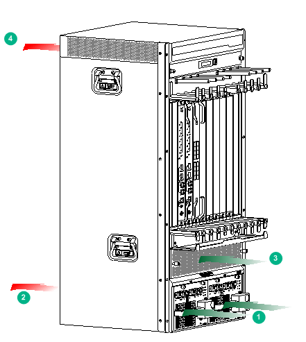
|
(1) Direction of the airflow into the power modules |
(2) Direction of the airflow out of the power modules |
|
(3) Direction of the airflow into the chassis |
(4) Direction of the airflow out of the chassis |
Figure 1-2 Airflow through other models of the S7500E chassis (S7503E)
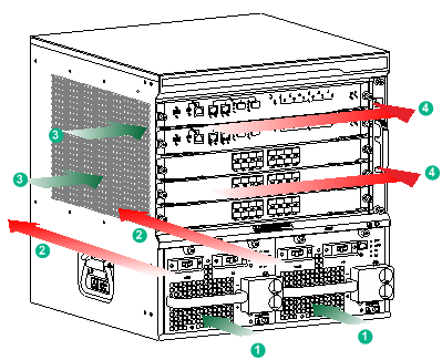
|
(1) Direction of the airflow into the power modules |
(2) Direction of the airflow out of the power modules |
|
(3) Direction of the airflow into the chassis |
(4) Direction of the airflow out of the chassis |
Space
For easy installation and maintenance, follow these space requirements:
· Reserve a minimum of 1 m (3.28 ft) of clearance between the rack and walls or other devices.
· For heat dissipation, make sure the headroom in the equipment room is no less than 3 m (9.84 ft).
· Make sure the rack has enough space to accommodate the switch. See Table 1-6 for rack requirements. For more information about chassis dimensions, see "Weights and dimensions."
Table 1-6 Switch dimensions and rack requirements
|
Model |
Chassis depth |
Rack requirements |
|
S7502E |
Total depth of 504 mm (19.84 in) · 61 mm (2.40 in) from the rack-facing surface of the mounting brackets to the front ends of the cable management brackets · 443 mm (17.44 in) from the rack-facing surface of the mounting brackets to the PoE terminal block cover at the chassis rear |
· A minimum of 0.8 m (2.62 ft) in depth · A minimum of 61 mm (2.40 in) between the front rack posts and the front door. · A minimum of 444 mm (17.48 in) between the front rack posts and the rear door. |
|
S7503E-S |
Total depth of 504 mm (19.84 in) · 61 mm (2.40 in) from the rack-facing surface of the mounting brackets to the front ends of the cable management brackets · 443 mm (17.44 in) from the rack-facing surface of the mounting brackets to the PoE terminal block cover at the chassis rear |
· A minimum of 0.8 m (2.62 ft) in depth · A minimum of 61 mm (2.40 in) between the front rack posts and the front door. · A minimum of 444 mm (17.48 in) between the front rack posts and the rear door. |
|
S7503E-M |
Total depth of 482 mm (18.98 in) · 61 mm (2.40 in) from the rack-facing surface of the mounting brackets to the front ends of the cable management brackets · 421 mm (16.57 in) from the rack-facing surface of the mounting brackets to the handle at the rear of the chassis |
· A minimum of 0.8 m (2.62 ft) in depth · A minimum of 61 mm (2.40 in) between the front rack posts and the front door. · A minimum of 425 mm (16.73 in) between the front rack posts and the rear door. |
|
S7503E |
Total depth of 514 mm (20.24 in) · 98 mm (3.86 in) from the rack-facing surface of the mounting brackets to the front ends of the cable management brackets · 416 mm (16.38 in) from the rack-facing surface of the mounting brackets to the handle at the rear of the chassis |
· A minimum of 0.8 m (2.62 ft) in depth · A minimum of 100 mm (3.94 in) between the front rack posts and the front door. · A minimum of 420 mm (16.54 in) between the front rack posts and the rear door. |
|
· S7506E-S · S7506E · S7506E (non-PoE) · S7506E-MF · S7506E-MF (non-PoE) |
Total depth of 515 mm (20.28 in) · 99 mm (3.90 in) from the rack-facing surface of the mounting brackets to the front ends of the cable management brackets · 416 mm (16.38 in) from the rack-facing surface of the mounting brackets to the handle at the rear of the chassis |
· A minimum of 0.8 m (2.62 ft) in depth · A minimum of 100 mm (3.94 in) between the front rack posts and the front door. · A minimum of 420 mm (16.54 in) between the front rack posts and the rear door. |
|
S7506E-V |
Total depth of 518 mm (20.39 in) · 102 mm (4.02 in) from the rack-facing surface of the mounting brackets to the front ends of the cable management brackets · 416 mm (16.38 in) from the rack-facing surface of the mounting brackets to the handle at the rear of the chassis |
· A minimum of 0.8 m (2.62 ft) in depth · A minimum of 102 mm (4.02 in) between the front rack posts and the front door. · A minimum of 420 mm (16.54 in) between the front rack posts and the rear door. |
|
S7510E |
Total depth of 514 mm (20.24 in) · 98 mm (3.86 in) from the rack-facing surface of the mounting brackets to the front ends of the cable management brackets · 416 mm (16.38 in) from the rack-facing surface of the mounting brackets to the handle at the rear of the chassis |
· A minimum of 0.8 m (2.62 ft) in depth · A minimum of 100 mm (3.94 in) between the front rack posts and the front door. · A minimum of 420 mm (16.54 in) between the front rack posts and the rear door. |
|
|
NOTE: The signal cables and power cords are routed through the front of the chassis. If you use power cords that have a conductor cross-section area of a minimum of 16 sq mm (0.02 sq in), leave more space between the front rack posts and the front door as appropriate. |
Figure 1-3 shows the depth of the S7502E and S7503E-S switches. Figure 1-4 shows the depth of the S7503E-M, S7503E, S7506E-S, S7506E (non-PoE), S7506E, S7506E-MF, S7506E-MF (non-PoE), S7506E-V, and S7510E switches.
Figure 1-3 Switch depth (S7503E-S switch)
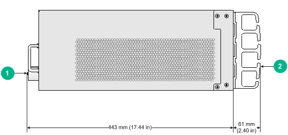
|
(1) PoE terminal block cover at the chassis rear |
(2) Cable management bracket |
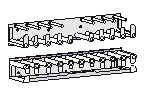
Figure 1-4 Switch depth (S7506E switch)
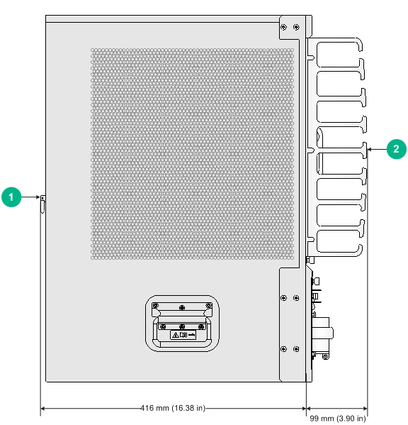
|
(1) Handle at the chassis rear |
(2) Cable management bracket |
Installation accessories and tools
Installation accessories
Table 1-7 Installation accessories
|
Item |
Quantity |
Compatible switch model/module |
|
Console cable
|
1 |
All S7500E switch models |
|
Grounding cable
|
1 |
All S7500E switch models |
|
Mounting bracket kit: ·
Mounting brackets ·
M4 countersunk head screw |
· 1 pair of mounting brackets. · M4 countersunk head screw quantity varies by switch model. ¡ S7502E: 8 ¡ S7503E: 12 ¡ S7503E-M: 8 ¡ S7503E-S: 8 ¡ S7506E: 12 ¡ S7506E (non-PoE): 12 ¡ S7506E-MF: 12 ¡ S7506E-MF (non-PoE): 12 ¡ S7506E-S: 12 ¡ S7506E-V: 24 ¡ S7510E: 12 |
All S7500E switch models |
|
Cable management bracket kit 1: ·
Cable management bracket ·
M3 countersunk head screw |
· 1 cable management bracket. · M3 countersunk head screw quantity varies by switch model. ¡ S7502E: 2 ¡ S7503E: 3 ¡ S7503E-M: 2 ¡ S7503E-S: 3 ¡ S7506E: 3 ¡ S7506E (non-PoE): 3 ¡ S7506E-MF: 3 ¡ S7506E-MF (non-PoE): 3 ¡ S7506E-S: 3 ¡ S7510E: 6 |
· S7502E · S7503E · S7503E-M · S7503E-S · S7506E · S7506E (non-PoE) · S7506E-MF · S7506E-MF (non-PoE) · S7506E-S · S7510E |
|
Cable management bracket kit 2: ·
Cable management bracket ·
M4 countersunk head screw |
· 1 cable management bracket. · 12 M4 countersunk head screws. |
S7506E-V |
|
M6 screw and cage nut
|
· S7502E: 4 sets · S7503E: 8 sets · S7503E-M: 4 sets · S7503E-S: 4 sets · S7506E: 8 sets · S7506E (non-PoE): 8 sets · S7506E-MF: 8 sets · S7506E-MF (non-PoE): 8 sets · S7506E-S: 8 sets · S7506E-V: 12 sets · S7510E: 12 sets |
All S7500E switch models |
|
ESD wrist strap
|
1 |
All S7500E switch models |
|
Tweezers for installing and removing transceiver modules |
1 |
· S7503E-M · S7506E · S7506E (non-PoE) · S7506E-MF · S7506E-MF (non-PoE) · S7506E-V · S7510E |
|
|
NOTE: Figures for the mounting bracket, cable management bracket, and power cord management bracket in Table 1-7 are for illustration only. |
Tools and equipment
Prepare the following tools and equipment yourself:
· Mechanical lift.
· Phillips screwdrivers P1–100 mm, P2–150 mm, and P3–250 mm.
· Flat-blade screwdriver P4–75 mm.
· Marker.
· Tape.
· Diagonal pliers, wire-stripping pliers, and wire clippers.
· M6 wrench.
· Cables such as network cables and fiber cables.
· Meters and equipment, such as hub and multimeter.
· Configuration terminal, such as PC.
|
|
NOTE: The rack installation accessories and tools vary by rack model and are not included in this section. For more information, see the installation guide for the rack. |
