- Table of Contents
-
- H3C S7500E Switch Series Installation Guide-6W108
- 00-Preface
- 01-Chapter 1 Preparing for Installation
- 02-Chapter 2 Installing the Switch
- 03-Chapter 3 Installing FRUs
- 04-Chapter 4 Connecting Your Switch to the Network
- 05-Chapter 5 Replacement Procedures
- 06-Chapter 6 Troubleshooting
- 07-Appendix A Chassis Views and Technical Specifications
- 08-Appendix B FRUs and Compatibility Matrixes
- 09-Appendix C LEDs
- 10-Appendix D Cables
- 11-Appendix E Engineering Labels for Cables
- 12-Appendix F Cable Management
- Related Documents
-
| Title | Size | Download |
|---|---|---|
| 05-Chapter 5 Replacement Procedures | 7.83 MB |
Replacing the power supply system
Replacing a power module adapter
Replacing an S7506E-V fan tray
Replacing an S7506E-MF/S7506E-MF (non PoE) fan tray
Replacing a fan tray for other models
Replacing air filters on an S7506E-V
Replacing an air filter for the other models
Replacing a transceiver module or network cable
Replacing a transceiver module
5 Replacement procedures
|
|
CAUTION: · Ensure electrical safety when you hot swap an FRU. · To avoid bodily injury and device damage, strictly follow the replacement procedure in this section when you replace a component. |
All FRUs of the S7500E series switches are hot swappable. You can replace any of them when the switch is operating. Figures for the chassis and FRUs are for illustration only.
Replacing mounting brackets
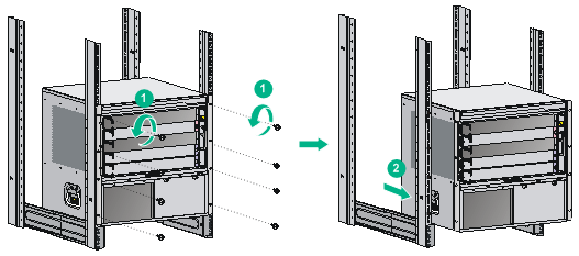
1. Remove the screws that secure the chassis to the rack.
2. Cooperate with one or more people to lift the chassis by holding chassis handles or by supporting the chassis bottom. Pull out the chassis along the guide rails until the space is enough for replacing the mounting brackets.
Figure 5-1 Pulling out the chassis (S7503E)
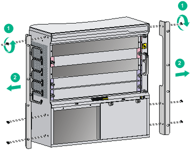
3. Remove the mounting brackets, as shown in Figure 5-2.
Figure 5-2 Removing mounting brackets (S7503E)
4. Install the new mounting brackets. For more information about how to install mounting brackets, see "Installing mounting brackets and cable management brackets."
5. Cooperate with one or more people to push the chassis back to the rack, and fasten the screws to secure the chassis to the rack. For more information, see "Mounting the switch in the rack."
Replacing the power supply system
Replacing a power module adapter
1. Prepare an antistatic mat to place the removed power module adapter.
2. Wear an ESD wrist strap and make sure it makes good skin contact and is reliably grounded. For more information, see "Attaching an ESD wrist strap."
3. Use a Phillips screwdriver to loosen the captive screws on the power module adapter.
4. Holding the power module adapter handle with one hand, pull it part way out of the slot. Supporting the adapter bottom with the other, pull it slowly out of the slot.
5. Place the power module adapter on the antistatic mat.
6. Install a new power module adapter in the slot. For the installation procedure, see "Installing a power module adapter."
Figure 5-3 Removing a power module adapter
Removing a power module
|
|
WARNING! · Do not install AC and DC power modules on the same switch. Do not install power modules of different models on the same switch. To avoid damage to the switch, power off the switch before you replace two power modules with different models. · When you use two power modules to supply power to the switch, make sure each power module has a separate circuit breaker. Before replacing a power module, turn off the circuit breaker on the power module. · To avoid device damage and bodily injury, strictly follow the procedure in Figure 5-4 and Figure 5-5 to remove and install a power module, respectively. |
|
|
CAUTION: Before replacing a PoE power module, make sure other PoE power modules are available in the switch for PoE power supply. |
Figure 5-4 Power module removal flow
![]()
Figure 5-5 Power module installation flow
![]()
To replace a power module:
1. Prepare an antistatic mat to place the removed power module.
2. Wear an ESD wrist strap and make sure it has a good skin contact and is reliably grounded. For more information, see "Attaching an ESD wrist strap."
3. Turn off the switch on the power module.
4. Remove the cable from the power module.
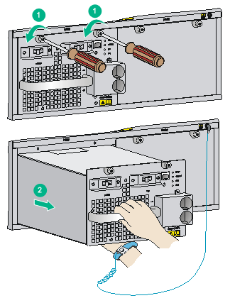
5. Use a Phillips screwdriver to loosen the captive screw on the power module, as shown by callout 1 in Figure 5-6.
6. Holding the power module handle with one hand and supporting the bottom of the power module with the other, gently pull the power module out, as shown by callout 2 in Figure 5-6.
7. Put the removed power module on the antistatic mat.
8. Install a new power module. For the installation procedures, see "Installing a power module."
After removing the power module, if you do not install a new power module, install a blank panel. As shown by callout 3 in Figure 5-6, align the screws on the blank panel with the screw holes on the switch, and then use a screwdriver to fasten the screws on the blank panel.
Figure 5-6 Removing the power module
Replacing a card
The card replacement procedures for the S7500E series are the same.
Remove the cables on a card before removing the card.
To replace a card:
1. Prepare an antistatic mat to place the removed card.
2. Wear an ESD wrist strap and make sure it has a good skin contact and is correctly grounded. For more information, see "Attaching an ESD wrist strap."
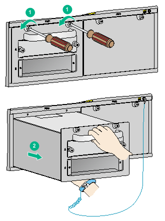
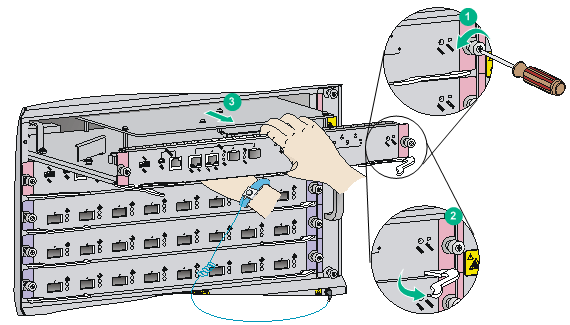
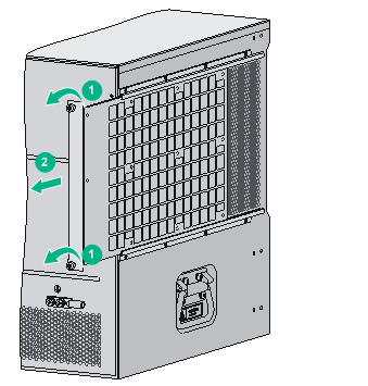
3. Use a Phillips screwdriver to remove the captive screw on the card, as shown by callout 1 in Figure 5-7.
4. Move the ejector levers outwards to separate the card from the backplane, as shown by callout 2 in Figure 5-7.
5. Use one hand to slowly move the card outwards. Supporting the bottom of the card with the other hand, pull the card out of the slot along slide rails, as shown by callout 3 in Figure 5-7.
6. Put the removed card on the antistatic mat.
7. Install a new card. For the installation procedures, see "Installing cards."
If no new card is to be installed, install a blank panel to ensure heat dissipation of the switch and prevent dust from entering the switch.
Replacing a fan tray
|
|
CAUTION: · When replacing the fan tray, do not touch the rotating fans to avoid bodily injury. · To ensure correct operation of the switch, install a new fan tray within five minutes after the fan tray is removed. · Make sure the fan tray handle is pushed into the slot after installation. |
When the fan tray fails, replace the fan tray to ensure correct operation of the switch.
|
|
NOTE: To examine fan status, use the display fan command. For more information, see H3C S7500E Switch Series Fundamentals Command Reference. |
Replacing an S7506E-V fan tray
Removing a fan tray
1. Prepare an antistatic mat to place the removed fan tray.
2. Wear an ESD wrist strap and make sure it has a good skin contact and is reliably grounded. For more information, see "Attaching an ESD wrist strap."
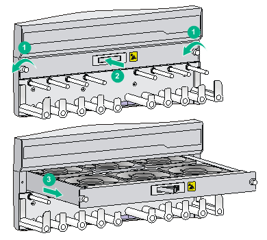
3. Use a screwdriver to remove the captive screw on the fan tray.
4. Press the left side of the fan tray handle to rotate it out from the slot.
5. Supporting the fan tray by its bottom with one hand, hold the fan tray handle with the other hand to pull the fan tray out of the slot.
6. Put the removed fan tray on the antistatic mat or its original shipping materials.
Figure 5-8 Removing a fan tray from an S7506E-V
Installing a fan tray
1. Wear an ESD wrist strap and make sure it has a good skin contact and is reliably grounded. For more information, see "Attaching an ESD wrist strap."
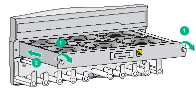
2. Unpack a new fan tray and push it into the fan tray slot along the slide rails until it has a close contact with the backplane.
3. Use a screwdriver to fasten the captive screw on the fan tray.
4. Examine the FAN LEDs on the MPU of the switch. If the OK LED is on, the fan tray is installed successfully. For more information about the FAN LEDs, see "Appendix C LEDs."
Figure 5-9 Installing a fan tray for an S7506E-V
Replacing an S7506E-MF/S7506E-MF (non PoE) fan tray
Removing a fan tray
1. Prepare an antistatic mat to place the removed fan tray.
2. Wear an ESD wrist strap and make sure it has a good skin contact and is reliably grounded. For more information, see "Attaching an ESD wrist strap."
3. Hold the fan tray handle and press the retaining latch to pull the fan tray out of the slot.
4. Put the removed fan tray on the antistatic mat or its original shipping materials.
Figure 5-10 Removing a fan tray from an S7506E-MF/S7506E-MF (non PoE)
Installing a fan tray
1. Wear an ESD wrist strap and make sure it has a good skin contact and is reliably grounded. For more information, see "Attaching an ESD wrist strap."
2. Unpack a new fan tray. Holding the fan tray handle and pressing the retaining latch, insert the fan tray into the fan tray slot along the slide rails until it snaps into place.
3. Examine the FAN LEDs on the MPU of the switch. If the OK LED is on, the fan tray is installed successfully. For more information about the FAN LEDs, see "Appendix C LEDs."
Figure 5-11 Installing a fan tray for an S7506E-MF/S7506E-MF (non PoE)

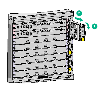
Replacing a fan tray for other models
Removing a fan tray
1. Prepare an antistatic mat to place the removed fan tray.
2. Wear an ESD wrist strap and make sure it has a good skin contact and is reliably grounded. For more information, see "Attaching an ESD wrist strap."
3. Use a screwdriver to remove the captive screw on the fan tray, as shown by callout 1 in Figure 5-12.
4. As shown by callout 2 in Figure 5-12, hold the handle of the fan tray to pull the fan tray out of the slot.
5. Put the removed fan tray on an antistatic mat or its original shipping materials.
Figure 5-12 Removing a fan tray from other models
Installing a fan tray
1. Wear an ESD wrist strap and make sure it has a good skin contact and is reliably grounded. For more information, see "Attaching an ESD wrist strap."
2. Unpack a new fan tray and insert it into the fan tray slot along the slide rails. Push the fan tray in the slot until it has a close contact with the backplane.
3. Use a screwdriver to fasten the captive screw on the fan tray.
4. Examine the FAN LEDs on the MPU of the switch. If the OK LED is on, the fan tray is installed successfully. For more information about the FAN LEDs, see "Appendix C LEDs."
Figure 5-13 Installing a fan tray for other models
Replacing an air filter
|
|
CAUTION: Clean air filters every three months to guarantee adequate ventilation and avoid over-temperature. |
The air filter of the S7506E-V is different from other models.
· The S7506E-V has two air filters on its front and rear panels. For how to replace the air filters, see "Replacing air filters on an S7506E-V."
· Other models of the S7500E series has only one air filter. For how to replace it, see "Replacing an air filter for the other models."
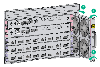
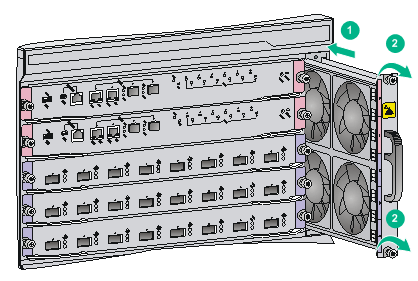
Replacing air filters on an S7506E-V
1. Use a Phillips screwdriver to remove the captive screws on the front and rear air filters, as shown by callout 1 in Figure 5-14.
2. Remove the front and rear air filters from the chassis, as shown by callout 2 in Figure 5-14.
3. Install the cleaned front and rear air filters to the switch. For the installation procedures, see "(Optional) Installing an air filter."
Figure 5-14 Removing an air filter for S7506E-V
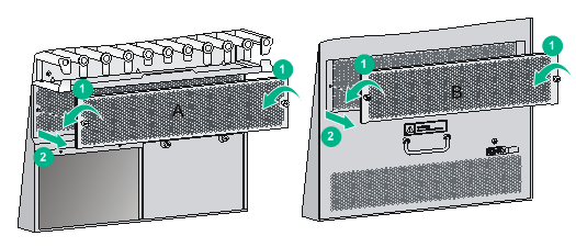
Replacing an air filter for the other models
1. Loosen the captive screw on the air filter, as shown by callout 1 in Figure 5-15.
2. Seize the captive screws on the air filter and slowly pull the air filter out of the chassis, as shown by callout 2 in Figure 5-15.
3. Install the cleaned air filter to the switch. For the installation procedures, see "(Optional) Installing an air filter."
Figure 5-15 Removing an air filter for the other models
Replacing a CF card
|
|
CAUTION: To prevent the file system on the hardware or the CF card from being damaged, do not remove the CF card when the switch is booting or the CF card LED is flashing. |
Before replacing a CF card, execute the umount command to unmount the CF card to ensure that the file system on the CF card is not damaged when you remove the CF card.
After you execute the umount cf command, if you want to continue to use the CF card, execute the mount cf command in user view to load the CF card again.
After you replace the CF card, the system automatically loads the CF card.
1. Log in to the switch to execute the umount command. For how to log in to the switch, see "Connecting your switch to the network."
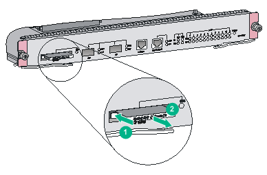
2. Use a hard object to press the eject button of the CF card reader as shown by callout 1 in Figure 5-16. The reader ejects the card part way out of the slot.
3. Remove the CF card from the reader and put it in an antistatic shielding bag.
4. Install a new CF card. For the installation procedures, see "(Optional) Installing a CF card on an MPU."
Figure 5-16 Replacing the CF card
Replacing a transceiver module or network cable
|
|
WARNING! Disconnected optical fibers or transceiver modules might emit invisible laser light. Do not stare into beams or view directly with optical instruments when the switch is operating. |
|
|
NOTE: You can use tweezers (provided with the switch) to install and remove transceiver modules or optical fibers on an S7503E-M, S7506E, S7506E (non-PoE), S7506E-MF, S7506E-MF (non-PoE), S7506E-V, or S7510E switch in case of limited space. |
Replacing a transceiver module
|
|
CAUTION: · Do not touch the golden plating on a transceiver module during the replacement process. · After removing a transceiver module, you must wait a minimum of 5 seconds before installing a new transceiver module. · Make sure the new transceiver module is the same model as the peer transceiver module at the other end of the optical fiber. |
Replacing an XFP/SFP+/SFP/QSFP+/QSFP28 module
The replacement procedure is similar for XFP modules, SFP+ modules, SFP modules, QSFP+, and QSFP28 modules. The following procedure replaces an SFP+ module.
To replace an SFP+ module:
1. Wear an ESD wrist strap and make sure it has a good skin contact and is reliably grounded. For more information, see "Attaching an ESD wrist strap."
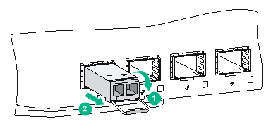
2. Remove the optical fibers from the module.
There is a latching mechanism between a fiber connector and transceiver module bore to prevent connector disengagement. Release the latching before removing the optical fiber. To avoid damages, do not use excessive force.
3. Pivot the bail latch down to the horizontal position.
For a QSFP+ or QSFP28 module that uses a plastic pull latch, skip this step.
4. Hold the bail latch to pull the module out of the slot. Make sure you apply force in the direction parallel to the ground. To avoid damaging the bail latch, do not use excessive force.
If you apply force at an angle when pulling the module out, you can hardly pull the module out and the module or fiber port might be damaged.
5. Insert dust plugs into the removed module, and put the module into its packaging bag.
6. Install a new module. For the installation procedure, see "Installing transceiver modules."
Figure 5-17 Removing an SFP+ transceiver module
Replacing a CFP module
1. Wear an ESD wrist strap and make sure it makes good skin contact and is reliably grounded.
For more information, see "Attaching an ESD wrist strap."
2. Remove the optical fibers from the module.
There is a latching mechanism between a fiber connector and transceiver module port to prevent connector disengagement. Release the latching before removing the optical fiber. To avoid damages, do not use excessive force.
3. Loosen the captive screws on the transceiver module.
4. Carefully pull the module out of the slot. Make sure you apply force in the direction parallel to the ground.
If you apply force at an angle, you can hardly pull the module out and the module or fiber port might be damaged.
5. Insert the plugs into the removed module, and put the module into its packaging bag.
6. Install a new module. For the installation procedure, see "Installing transceiver modules."
Figure 5-18 Removing a CFP module
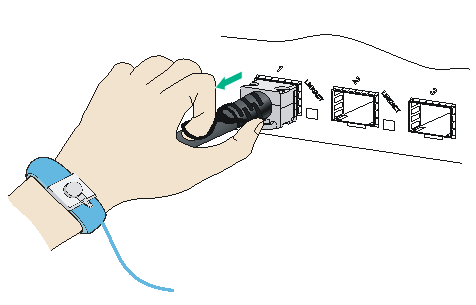
Replacing a network cable
|
|
CAUTION: · Do not touch the golden plating on the two modular ends of a network cable during the replacement process. · Make sure the two modular ends of the new network cable are compatible with the ports into which they will be inserted. · To avoid network cable damage and signal loss, do not strain or tangle a network cable. · Before inserting a modular end of a network cable into a port, make sure the module aligns with the port correctly. · If a network cable cannot be removed or installed, verify that the removal or installation procedure is correct. Do not use excessive force. |
The replacement procedure is the same for network cables. The following procedure replaces an SFP+ DAC cable.
To replace an SFP+ DAC cable:
1. Wear an ESD wrist strap and make sure it has a good skin contact and is reliably grounded. For more information, see "Attaching an ESD wrist strap."
2. Push the modular end of the cable gently inward to release the latching mechanism. Then use the pull latch on the cable to pull the modular end out of the slot. Make sure you apply force in the direction parallel to the ground. To avoid damaging the pull latch, do not use excessive force.
If you apply force at an angle when pulling the module out, you can hardly pull the network cable out and the network cable or fiber port might be damaged.
Figure 5-19 Removing an SFP+ DAC cable
3. Install a new cable. For the installation procedures, see "Connecting network cables."
Replacing the PoE DIMM
Before replacing a PoE DIMM, remove the cables on the card where the PoE DIMM is installed, and then remove the card from the switch. For how to remove a card, see "Replacing a card."
To replace a PoE DIMM:
1. Wear an ESD wrist strap and make sure it has a good skin contact and is reliably grounded. For more information, see "Attaching an ESD wrist strap."
2. Make sure the card is sturdy. Find the PoE DIMM slot.
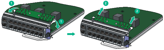
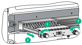
3. Pull the white clips on the two sides of the PoE DIMM slot outward, as shown by callout 1 in Figure 5-20.
4. Pull the PoE DIMM out along the guide rails, as shown by callout 2 in Figure 5-20.
5. Put the removed PoE DIMM on its original shipping materials.
6. Install a new PoE DIMM. For the installation procedures, see "Installing a PoE DIMM."
Figure 5-20 Removing a PoE DIMM