- Table of Contents
-
- H3C S7500E Switch Series Installation Guide-6W108
- 00-Preface
- 01-Chapter 1 Preparing for Installation
- 02-Chapter 2 Installing the Switch
- 03-Chapter 3 Installing FRUs
- 04-Chapter 4 Connecting Your Switch to the Network
- 05-Chapter 5 Replacement Procedures
- 06-Chapter 6 Troubleshooting
- 07-Appendix A Chassis Views and Technical Specifications
- 08-Appendix B FRUs and Compatibility Matrixes
- 09-Appendix C LEDs
- 10-Appendix D Cables
- 11-Appendix E Engineering Labels for Cables
- 12-Appendix F Cable Management
- Related Documents
-
| Title | Size | Download |
|---|---|---|
| 04-Chapter 4 Connecting Your Switch to the Network | 654.78 KB |
4 Connecting your switch to the network
Accessing the switch for the first time
Setting up the configuration environment
Connecting the switch to the network
Connecting your switch to the network through twisted pair cables
Connecting your switch to the network through optical fibers
Connecting the switch to the network through copper cables
4 Connecting your switch to the network
This chapter describes how to connect your switch to a network.
Accessing the switch for the first time
The first time you access the switch you must use a console cable to connect a console terminal, for example, a PC, to the console port or USB console port on the switch.
Setting up the configuration environment
If both the console port and the USB console port are used, you can only access the switch through the USB console port.
Console cables
· Console cable connecting the console port on the switch and the serial port on a terminal
The console cable has a crimped RJ-45 connector for connecting to the console port of the switch, and a DB-9 connector for connecting to the 9-core serial port on the terminal.
Figure 4-1 shows the console cable and Table 4-1 shows its pinouts.
Figure 4-1 Console cable connecting the serial port and the console port
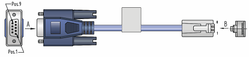
Table 4-1 Pinouts for the console cable connecting the serial port and the console port
|
RJ-45 pin |
Signal |
DB-9 pin |
Signal |
|
1 |
RTS |
8 |
CTS |
|
2 |
DTR |
6 |
DSR |
|
3 |
TXD |
2 |
RXD |
|
4 |
CD |
5 |
SG |
|
5 |
GND |
5 |
SG |
|
6 |
RXD |
3 |
TXD |
|
7 |
DSR |
4 |
DTR |
|
8 |
CTS |
7 |
RTS |
· Console cable connecting the USB console port on the switch and the USB port on a terminal
The console cable has one mini-USB A/B connector for connecting to the USB console port on the switch and one USB A connector for connecting to the USB port on the terminal.
Figure 4-2 shows the console cable and Table 4-2 shows its pinouts.
Figure 4-2 Console cable connecting the USB port and the USB console port
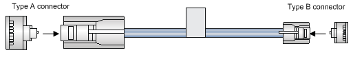
Table 4-2 Pinouts for the console cable connecting the USB port and the USB console port
|
USB A pin |
Signal |
mini-USB A/B pin |
Signal |
|
1 |
VBUS |
1 |
VBUS |
|
2 |
D- |
2 |
D- |
|
3 |
D+ |
3 |
D+ |
|
|
|
4 |
ID(NC) |
|
4 |
GND |
5 |
GND |
Connecting the console port to the terminal
|
|
IMPORTANT: · Identify the mark on the console port and USB console port and make sure you are connecting to the correct port. · The serial ports on PCs do not support hot swapping. To connect a PC to an operating device, first connect the PC end. To disconnect a PC from an operating device, first disconnect the device end. |
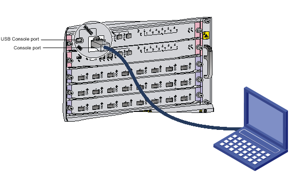
To connect the console cable to the console port:
1. Connect the DB-9 connector of the console cable to the serial port on a PC or terminal.
2. Connect the RJ-45 connector of the console cable to the console port on the MPU of the switch.
To connect the console cable to the USB console port:
1. Connect the USB-A connector of the console cable to the USB port on a PC or terminal.
2. Connect the mini-USB A/B connector of the console cable to the USB console port on the MPU of the switch.
Figure 4-3 Connecting the console port to the terminal
Setting terminal parameters
To configure and manage the switch through the console port, you must run a terminal emulator program, TeraTermPro or PuTTY, on your configuration terminal. You can use the emulator program to connect a network device, a Telnet site, or an SSH site. For more information about the terminal emulator programs, see the user guides for these programs.
The following are the required terminal settings:
· Bits per second—9,600.
· Data bits—8.
· Stop bits—1.
· Parity—None.
· Flow control—None.
Powering on the switch
Before powering on the switch, verify that the following conditions are met:
· The switch has been steadily mounted.
· All the cards have been correctly installed.
· All the network cables, power cords, and grounding cables have been correctly connected.
· The voltage of power supply can meet the requirements of the switch.
· The console cable has been correctly connected. The configuration terminal has been started, and the terminal parameters have been configured.
To power on the switch:
Turn on the power supply and power modules of the switch to power on the switch.
Command output varies by software version. The following is a sample output you can see on the terminal:
RAM test successful.
Press Ctrl+T to start five-step full RAM test...
Press Ctrl+Y to start nine-step full RAM test...
System is starting...
Press Ctrl+D to access BASIC-BOOTWARE MENU...
Booting Normal Extended BootWare
The Extended BootWare is self-decompressing........Done.
****************************************************************************
* *
* BootWare, Version 1.13 *
* *
****************************************************************************
Compiled Date : Oct 21 2014
CPU Type : XLP208
CPU Clock Speed : 1000MHz
Memory Type : DDR3 SDRAM
Memory Size : 2048MB
Memory Speed : 667MHz
BootWare Size : 1536KB
Flash Size : 4MB
BASIC CPLD Version : 001
EXTENDED CPLD Version : 008A
PCB Version : Ver.B
BootWare Validating...
Press Ctrl+B to access EXTENDED-BOOTWARE MENU...
Loading the main image files...
Loading file flash:/7500-cmw710-system-a7146.bin............................
............................................................................
.....................................................................Done.
Loading file flash:/7500-cmw710-devkit-a7146.bin.................Done.
Loading file flash:/7500-cmw710-manufacture-a7146.bin...Done.
Loading file flash:/7500-cmw710-boot-a7146.bin...........................
Done.
Image file flash:/7500-cmw710-boot-a7146.bin is self-decompressing..........
...................................................Done.
System image is starting...
Cryptographic algorithms tests passed.
Line aux0 is available.
Press ENTER to get started.
Press Enter at the prompt. When the prompt <Sysname> appears, you can configure the switch.
|
|
NOTE: For more information about the CLI, see H3C S7500E Switch Series Fundamentals Configuration Guide. |
After powering on the switch, verify the following items:
· The cooling system is operating. You can hear fan rotating noise and feel air being blown out.
· All the system LEDs on the MPUs show that the system is operating correctly. For more information about the LED status, see "Appendix C LEDs."
Connecting the switch to the network
Before you connect the switch to the network, verify that all its basic settings are correct.
After the switch is connected to the network, use the ping or tracert command to test the network connectivity. For more information about the two commands, see H3C S7500E Switch Series Network Management and Monitoring Command Reference.
For more information about twister pair cable, optical fibers, and copper cables, see "Appendix D Cables."
Connecting your switch to the network through twisted pair cables
To connect your switch to the network through twisted pair cables:
1. Connect one end of the twisted pair cable to the RJ-45 Ethernet port of your switch.
2. Connect the other end of the twisted pair cable to the RJ-45 Ethernet port of the access device in the network.
3. Examine the port LEDs for incorrect connection.
For more information about the LED status, see "Appendix C LEDs."
Connecting your switch to the network through optical fibers
|
|
WARNING! To avoid injury to your eyes, do not stare at the fiber ports and connectors when connecting optical fibers. |
You can install a transceiver module in a fiber port and use optical fibers to connect the port to the network. For more information about transceiver modules, see "(Optional) Installing transceiver modules and network cables."
Follow these requirements when you are connecting optic fibers:
· Make sure the fiber connector and fiber type match the transceiver module type.
· The fiber ports on some cards have dust plugs. Remove the dust plugs before using the fiber ports. Keep the removed dust plugs for future use. Fiber ports must be installed with dust plugs when they are not in use.
· Fiber connectors are protected by dust covers. Remove the dust covers before using the fiber connectors. Keep the removed dust covers for future use. Fiber connectors must be installed with dust caps when they are not in use. Replace the dust cover if it is loose or polluted.
· Before connecting a fiber, use dust free paper and absolute alcohol to clean the end face of the fiber connector. You can brush the end face only in one direction. You also need to brush the end face of the fiber port.
· Never bend or curve a fiber when connecting it. After a fiber is installed, the bend radius must be not less than 40 mm (the minimum dynamic bend radius is 20 D, and the minimum static bend radius is 10 D. D indicates the outer diameter of dust caps).
· If the fiber has to pass through a metallic board hole, the hole must have a sleek and fully filleted surface (the filleting radius must be not less than 2 mm). When passing through a metallic board hole or bending along the acute side of mechanical parts, the fiber must wear jackets or cushions.
· Never use excessive force to the fiber connector. Never pull, press, or extrude the fiber fiercely. For the allowed maximum tensile load and crush load, see "Appendix D Cables."
The installation of different optical fiber connectors is similar.
To connect your switch to the network through optical fibers:
1. Install a transceiver module into the port.
2. Remove the dust cover of the optical fiber connector, and clean the end of the optical fiber.
3. Remove the dust plug of the transceiver module, connect one end of the optical fiber to the transceiver module in the switch, and connect the other end into the transceiver module in the peer device.
¡ For how to connect an LC connector, see Figure 4-4.
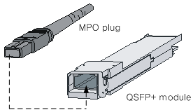
¡ For how to connect an MPO connector, see Figure 4-5.
4. Examine the port LEDs for incorrect connection.
For more information about the LED status, see "Appendix C LEDs."
|
|
NOTE: For the QSFP+ module, you do not need to differentiate between the transmitter (TX) and receiver (RX) ports. For other types of transceiver modules, the Tx port on one end must connect to the RX port on the other end. |
Figure 4-4 Using an LC optical fiber connector to connect an SFP module
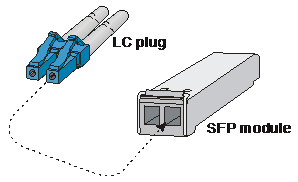
Figure 4-5 Using an MPO optical fiber connector to connect a QSFP module
Connecting the switch to the network through copper cables
For how to connect the S7500E switch to the network through copper cables, see "(Optional) Installing transceiver modules and network cables."
