- Table of Contents
-
- H3C S7500E Switch Series Installation Guide-6W108
- 00-Preface
- 01-Chapter 1 Preparing for Installation
- 02-Chapter 2 Installing the Switch
- 03-Chapter 3 Installing FRUs
- 04-Chapter 4 Connecting Your Switch to the Network
- 05-Chapter 5 Replacement Procedures
- 06-Chapter 6 Troubleshooting
- 07-Appendix A Chassis Views and Technical Specifications
- 08-Appendix B FRUs and Compatibility Matrixes
- 09-Appendix C LEDs
- 10-Appendix D Cables
- 11-Appendix E Engineering Labels for Cables
- 12-Appendix F Cable Management
- Related Documents
-
| Title | Size | Download |
|---|---|---|
| 10-Appendix D Cables | 230.91 KB |
10 Appendix D Cables
This chapter describes the cables used for connecting network ports.
Table 10-1 Cable description
|
Cable |
Port type |
Application |
|
Console cable |
Console port at one end and 9-pin serial port at the other end |
Enables users to perform debugging, configuration, maintenance, management, and software loading on the device. |
|
USB console cable |
USB console port at one end and USB port at the other end |
|
|
RJ-45 Ethernet ports |
Connects RJ-45 Ethernet ports to transmit data |
|
|
XFP/SFP+/SFP/CFP/QSFP+/EPON ports |
Connects the fiber ports to transmit data |
|
|
SFP+ ports |
Connects SFP+ ports to transmit data |
|
|
QSFP+ ports |
Connects QSFP+ ports to transmit data |
|
|
QSFP28 ports |
Connects QSFP28 ports to transmit data |
|
|
QSFP+ port at one end, and SFP+ port at the other end |
Connects a QSFP+ port to an SFP+ port |
Ethernet twisted pair cable
An Ethernet twisted pair cable consists of four pairs of insulated wires twisted together. It mainly transmits analog signals and is advantageous in transmitting data over shorter distances. The maximum transmission distance is 100 m (328.08 ft).
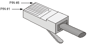
RJ-45 connector
An Ethernet twisted pair cable connects network devices through the RJ-45 connectors at the two ends. Figure 10-1 shows the pinouts of an RJ-45 connector.
Figure 10-1 RJ-45 connector pinout diagram
Cable pinouts
EIA/TIA cabling specifications define two standards: 568A and 568B for cable pinouts.
· Standard 568A—Pin 1: white/green stripe, pin 2: green solid, pin 3: white/orange stripe, pin 4: blue solid, pin 5: white/blue stripe, pin 6: orange solid, pin 7: white/brown stripe, pin 8: brown solid.
· Standard 568B—Pin 1: white/orange stripe, pin 2: orange solid, pin 3: white/green stripe, pin 4: blue solid, pin 5: white/blue stripe, pin 6: green solid, pin 7: white/brown stripe, pin 8: brown solid.
Cable type
Based on performance
Table 10-2 Ethernet cable description
|
Type |
Description |
|
Category 5 |
Transmits data at a maximum speed of 100 Mbps, with a bandwidth of 100 MHz. |
|
Category 5e |
Transmits data at a maximum speed of 1000 Mbps, with a bandwidth of 100 MHz. |
|
Category 6 |
Transmits data at a maximum speed of 10 Gbps, with a bandwidth of 250 MHz. |
|
|
NOTE: The RJ-45 Ethernet ports use category 5 or higher Ethernet twisted pair cables for connection. |
Based on pinouts
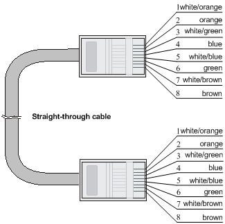
Ethernet twisted pair cables can be classified into straight through and crossover cables based on their pinouts.
· Straight-through—The pinouts at both ends comply with standard 568B, as shown in Figure 10-2.
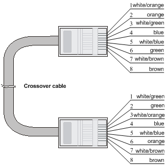
· Crossover—The pinouts at one end comply with standard 568B, and those at the other end comply with standard 568A, as shown in Figure 10-3.
Figure 10-2 Straight-through cable
Pin assignments
Select an Ethernet twisted pair cable according to the RJ-45 Ethernet port type on your device. An RJ-45 Ethernet port can be MDI (for routers and PCs) or MDIX (for switches). For the pinouts of RJ-45 Ethernet ports, see Table 10-3 and Table 10-4.
Table 10-3 RJ-45 MDI port pinouts
|
10BASE-T/100BASE-TX |
1000BASE-T |
|||
|
Signal |
Function |
Signal |
Function |
|
|
1 |
Tx+ |
Send data |
BIDA+ |
Bi-directional data cable A+ |
|
2 |
Tx- |
Send data |
BIDA- |
Bi-directional data cable A- |
|
3 |
Rx+ |
Receive data |
BIDB+ |
Bi-directional data cable B+ |
|
4 |
Reserved |
— |
BIDC+ |
Bi-directional data cable C+ |
|
5 |
Reserved |
— |
BIDC- |
Bi-directional data cable C |
|
6 |
Rx- |
Receive data |
BIDB- |
Bi-directional data cable B- |
|
7 |
Reserved |
— |
BIDD+ |
Bi-directional data cable D+ |
|
8 |
Reserved |
— |
BIDD- |
Bi-directional data cable D- |
Table 10-4 RJ-45 MDI-X port pinouts
|
Pin |
10BASE-T/100BASE-TX |
1000BASE-T |
||
|
Signal |
Function |
Signal |
Function |
|
|
1 |
Rx+ |
Receive data |
BIDB+ |
Bi-directional data cable B+ |
|
2 |
Rx- |
Receive data |
BIDB- |
Bi-directional data cable B- |
|
3 |
Tx+ |
Send data |
BIDA+ |
Bi-directional data cable A+ |
|
4 |
Reserved |
— |
BIDD+ |
Bi-directional data cable D+ |
|
5 |
Reserved |
— |
BIDD- |
Bi-directional data cable D- |
|
6 |
Tx- |
Send data |
BIDA- |
Bi-directional data cable A- |
|
7 |
Reserved |
— |
BIDC+ |
Bi-directional data cable C+ |
|
8 |
Reserved |
— |
BIDC- |
Bi-directional data cable C- |
To ensure normal communication, the pins for sending data on one port should correspond to the pins for receiving data on the peer port. When both of the ports on the two devices are MDI or MDIX, a crossover Ethernet cable is needed. A cross-over cable connects devices of the same type. When one port is MDI and the other is MDIX, a straight-through Ethernet cable is needed. A straight-through cable connects devices of different types.
If an RJ-45 Ethernet port with MDI/MDIX autosensing enabled can automatically negotiate pin roles. The S7500E RJ-45 Ethernet ports support MDI/MDIX. By default, MDI/MDIX is enabled on a port.
Making an Ethernet twisted pair cable
1. Cut the cable to length with the crimping pliers.
2. Strip off an appropriate length of the cable sheath. The length is typically that of the RJ-45 connector.
3. Untwist the pairs so that they can lie flat, and arrange the colored wires based on the wiring specifications.
4. Cut the top of the wires even with one another. Insert the wires into the RJ-45 end and make sure the wires extend to the front of the RJ-45 end and make good contact with the metal contacts in the RJ-45 end and in the correct order.
5. Crimp the RJ-45 connector with the crimping plier until you hear a click.
6. Repeat the above steps with the other end of the cable.
7. Use a cable tester to verify the connectivity of the cable.
Optical fiber
|
|
CAUTION: Use the same types of transceiver modules, pigtail cords, patch cords, and fiber cables. If you use single-mode optical fibers, the transceiver modules, pigtail cords, patch cords, and fiber cables must be single-mode. |
Optical fiber
Optical fibers are widely used in fiber-optic communications, which are advantageous for long-distance communications.
Optical fibers can be classified into the following types:
· Single mode fiber—It has a core size of 10 µm, and has a lower modal dispersion. It carries only a single ray of light. It is mostly used for communication over longer distances.
· Multi-mode fiber—It has a core size of 50 µm or 62.5 µm or higher, and has a higher modal dispersion than single-mode optical fiber. It is mostly used for communication over shorter distances.
Table 10-5 Allowed maximum tensile force and crush load
|
Period of force |
Tensile load (N) |
Crush load (N/mm) |
|
Short period |
150 |
500 |
|
Long term |
80 |
100 |
Optical fiber cable
An optical fiber cable is a cable containing one or more optical fibers. The optical fiber elements are typically individually coated with plastic layers and contained in a protective tube. Optical fiber cables fall into single-mode and multi-mode.
Patch cord
A fiber that has connectors at both ends is called a patch cord. A patch cord connects one optical device to another for signal routing. Patch cords fall into single-mode and multi-mode patch cords.
· Single-mode patch cord—The jacket is yellow. It permits transmission over longer distances.
· Multi-mode patch cord—The jacket is orange. It permits transmission over shorter distances.
Patch cords are classified into SC, LC, and FC patch cords based on interface type. The length of a patch cord can be 0.5 m (1.64 ft), 1 m (3.28 ft), 2 m (6.56 ft), 3 m (9.84 ft), 5 m (16.40 ft), and 10 m (32.81 ft).
Pigtail cord
A pigtail cord is an optical fiber that has an optical connector on one end and a length of exposed fiber on the other. The end of the pigtail is fusion spliced to a fiber, connecting the fiber cable and transceiver.
Pigtail cords fall into single-mode (yellow) and multi-mode (orange), and can also be classified into SC, LC, and FC pigtail cords based on interface type.
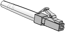
Fiber connector
Figure 10-4 SC connector
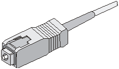
SFP+ DAC cable
You can use SFP+ DAC cables to connect the SFP+ ports. SFP+ DAC cables support the SFP+ standard and use 10-GE SFP+ Cu standard cables.
Figure 10-6 SFP+ DAC cable
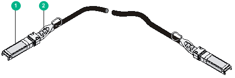
|
(1) Connector |
(2) Pull latch |
QSFP+ DAC/QSFP28 DAC cable
You can use QSFP+ DAC cables to connect QSFP+ ports.
You can use QSFP28 DAC cables to connect QSFP28 ports. The QSFP28 DAC cables are similar to QSFP+ DAC cables in appearance.
Figure 10-7 QSFP+ DAC cable
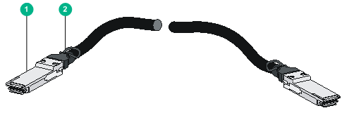
|
(1) Connector |
(2) Pull latch |
QSFP+ to SFP+ DAC cable
A QSFP+ to SFP+ DAC cable provides one QSFP+ connector at one end and four SFP+ connectors at the other end.
Figure 10-8 QSFP+ to SFP+ DAC cable
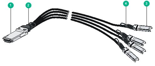
|
(1) QSFP+ connector |
(2) QSFP+ pull latch |
|
(3) SFP+ connector |
(4) SFP+ pull latch |
