- Table of Contents
-
- H3C S7500E Switch Series Installation Guide-6W108
- 00-Preface
- 01-Chapter 1 Preparing for Installation
- 02-Chapter 2 Installing the Switch
- 03-Chapter 3 Installing FRUs
- 04-Chapter 4 Connecting Your Switch to the Network
- 05-Chapter 5 Replacement Procedures
- 06-Chapter 6 Troubleshooting
- 07-Appendix A Chassis Views and Technical Specifications
- 08-Appendix B FRUs and Compatibility Matrixes
- 09-Appendix C LEDs
- 10-Appendix D Cables
- 11-Appendix E Engineering Labels for Cables
- 12-Appendix F Cable Management
- Related Documents
-
| Title | Size | Download |
|---|---|---|
| 02-Chapter 2 Installing the Switch | 4.83 MB |
Confirming installation preparations
Attaching slide rails and cage nuts to the rack
Installing cage nuts for attaching mounting brackets
Installing the accessories on the switch
Installing mounting brackets and cable management brackets
(Optional) Installing an air filter
Mounting the switch in the rack
Connecting the grounding cable
Connecting the grounding cable to a grounding strip
Grounding the switch through the AC power supply
Grounding the switch through the RTN wire of a DC power supply
2 Installing the switch
|
|
IMPORTANT: Keep the packages of the switch and the components for future use. |
Figures for the chassis and FRUs are for illustration only.
Installation flow
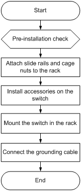
Table 2-1 Installation flow description
|
Step |
Remarks |
|
Preparations before installation |
|
|
· For how to install slide rails, see "Installing slide rails." · For how to install cage nuts, see "Installing cage nuts for attaching mounting brackets" |
|
|
Accessories to be installed on the chassis: · For how to mount brackets and cable management brackets, see "Installing mounting brackets and cable management brackets." · For how to install an air filter (optional), see "(Optional) Installing an air filter." |
|
|
N/A |
|
|
N/A |
Confirming installation preparations
Before you install an S7500E switch in a rack, verify the following items:
· You have read the chapter "Preparing for installation" carefully and the installation site meets all the requirements.
· A 19-inch rack is ready for use. For how to install a rack, see the rack installation guide.
· The rack is sturdy and reliably grounded.
· The installation position on the rack is appropriate for the chassis.
· No debris exists inside or around the rack.
· The switch is ready for installation and has been carried to a place near the rack and convenient for moving.
|
|
IMPORTANT: To ensure the stability of the rack, mount the switch at the lowest possible position. To mount multiple switches on the rack, mount the heaviest switch at the bottom of the rack. |
Attaching slide rails and cage nuts to the rack
Installing slide rails
Before installing the switch to the rack, install slide rails to the rack. If the rack has slide rails, skip this section.
Before installing the slide rails, verify that the slide rails can support the weight of the switch. For the weights of the S7500E series, see "Weights and dimensions."
As a best practice, order the H3C Slide Rail Accessories,500mm-800mm (LSTM2KSGD0) for the switch.
Position the chassis of the S7500E series according to their heights. For the specifications of the S7500E series, see "Weights and dimensions."
The slide rail installation procedure varies by rack type The following installation procedure is for your reference only.
To install a slide rail:
1. Read the signs on the slide rails (see Table 2-2) to avoid installation mistakes.
Figure 2-2 Right slide rail
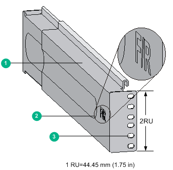
|
(1) Guide rail |
(2) Sign |
(3) Installation hole |
Table 2-2 Description for signs on the slide rails
|
Sign |
Meaning |
Remarks |
|
F/L |
Front end of the left slide rail |
Mount this end to the front left rack post. |
|
F/R |
Front end of the right slide rail |
Mount this end to the front right rack post. |
2. Mark the position on the rack for installing the slide rail.
¡ Make sure the bottom edge of the slide rail aligns with the middle of the narrower metal area between holes on a rack post, as shown in Figure 2-3.
¡ Each rack post requires six screws to secure the slide rail. You only need to mark the uppermost square hole and lowermost square hole for installation.
¡ Mark the square holes at the same height on the other three rack posts.
|
|
NOTE: One rack unit has three holes, the middle of which is an auxiliary installation hole, and the other two are standard installation holes. You can distinguish them by the space between each two holes. The space between a standard installation hole and an auxiliary installation hole is larger than the space between two adjacent standard installation holes. |
Figure 2-3 Locating the position on the rack for installing the slide rail
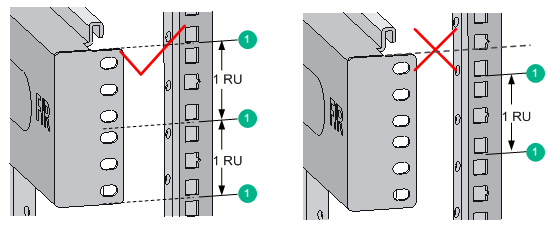
|
(1) Middle of the narrower metal area between holes |
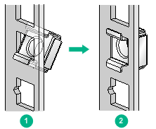
3. Install six cage nuts on the square holes in each rack post, as shown in Figure 2-4.
Figure 2-4 Installing a cage nut
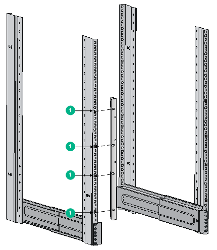
4. Align the installation holes on the front end of a slide rail with the cage nuts on the front rack post, and secure them with screws, as shown in Figure 2-5.
Figure 2-5 Attaching a slide rail to a front rack post
5. Keep the slide rail horizontally and adjust its length until the installation holes on the rear end of the slide rail touch the cage nuts on the rear rack post. Then fasten the screws.
|
|
TIP: Install a screw in each mounting hole of the slide rail to ensure its weight bearing capacity. |
6. Repeat step 4 and step 5 to install the other slide rail. Make sure the two slide rails are at the same height so the device can be placed on them horizontally.
Figure 2-6 Installed slide rails
Installing cage nuts for attaching mounting brackets
1. Determine and mark the cage nut installation holes on the front rack posts ,as shown in Figure 2-7.
2. Install cage nuts, as shown in Figure 2-4.
Figure 2-7 Installing cage nuts (S7503E)
|
|
|
|
NOTE: When preparing for installation, make sure the total height of the switches to be installed is not higher than the height of the rack. |
Installing the accessories on the switch
Installing mounting brackets and cable management brackets
Before installing the switch in the rack, install the mounting brackets and cable management brackets shipped with the switch. Mounting brackets are used for attaching the chassis to the rack, and cable management brackets are used for cabling the switch.
· S7506E-V—Install the mounting brackets and cable management brackets separately to the chassis. For more information, see "Installing the cable management brackets on the S7506E-V" and "Installing the mounting brackets."
· Other models—Install the cable management brackets to the mounting brackets, and then install the mounting brackets to the chassis. For more information, see "Installing the cable management brackets on other models" and "Installing the mounting brackets."
Installing the cable management brackets on the S7506E-V
The S7506E-V has two cable management brackets: the one with a tray is installed at the lower part of the switch, and the one without a tray is installed at the upper part of the switch. They are installed in the same way.
To install a cable management bracket:
1. Unpack the cable management brackets.
2. Attach the cable management bracket to the chassis, and align the screws with the screw holes in the chassis, as shown in Figure 2-8.
3. Fasten the screws.
Figure 2-8 Installing cable management brackets on an S7506E-V
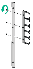
Installing the cable management brackets on other models
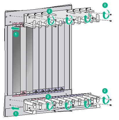
For the models except the S7506E-V, install the cable management bracket on the left mounting bracket, as shown in Figure 2-9. The switch is supplied with two mounting brackets, and the one with the cable management bracket screw holes is the left mounting bracket.
Figure 2-9 Attaching the cable management bracket to the left mounting bracket
Installing the mounting brackets
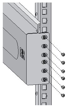
Before installing the switch in the rack, install the mounting brackets to the chassis, as shown in Figure 2-10.
· S7506E-V—Facing the front of the switch, mount the left and right mounting brackets to the two sides of the switch.
· Other models—Facing the front of the switch, mount the mounting bracket with a cable management bracket to the left of the switch, and mount the mounting bracket without a cable management bracket to the right of the switch (where the fan tray is located).
Figure 2-10 Installing the mounting brackets (S7503E)
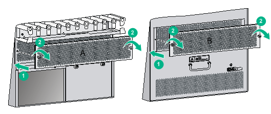
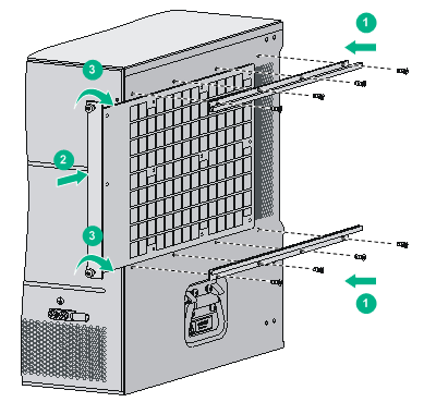
(Optional) Installing an air filter
Air filters are optional for the S7500E switches. If you have ordered air filters, install the air filters before mounting the switch in the rack.
· S7506E-V—An air filter is available at both front and rear of the switch, and can be installed in the same way. For the installation procedures, see "Installing an air filter on an S7506E-V."
· Other models—The air filter is located at the left of the chassis. For the installation procedures, see "Installing an air filter on other chassis models."
Installing an air filter on an S7506E-V
1. Unpack the air filter.
2. As shown by callout 1 in Figure 2-11, attach the air filter to the intake vents on the front panel or rear panel, and then insert the captive screws into the screw holes on the chassis.
3. Faster the captive screws, as shown by callout 2 in Figure 2-11.
Figure 2-11 Installing an air filter on an S7506E-V
|
(1) Front air filter |
(2) Rear air filter |
Installing an air filter on other chassis models
1. Unpack the air filter and fastening strips.
2. Align the screw holes in the fastening strip with the screw holes in the chassis, insert the screws into the screw holes, and then fasten the screws clockwise with a screwdriver, as shown in by callout 1 in Figure 2-12.
3. Push the air filter in between the fastening strips, as shown by callout 2 in Figure 2-12.
4. Fasten the captive screws, as shown by callout 3 in Figure 2-12.
Figure 2-12 Installing an air filter (S7503E)
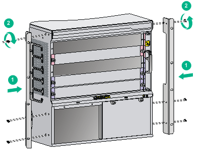
Mounting the switch in the rack
|
|
CAUTION: · Do not hold the handle of the fan tray, power module, or the back cover of the chassis, or the air vents of chassis to move the switch. Any attempt to carry the switch with these parts might cause equipment damage or even bodily injury. · Use a mechanical lift for switches of a high weight. · After placing the switch on the slide rails, do not leave go of your hands immediately because this might tip and damage the switch, and even cause bodily injury. |
To mount the switch in the rack:
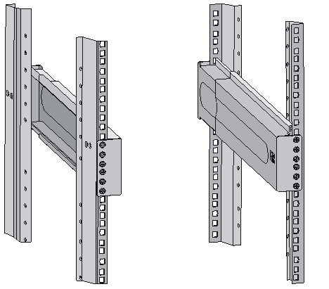
1. Face the rear of the chassis towards the front of the rack.
2. Use a minimum of two people to lift the switch until the bottom of the switch is a little higher than the slide rails on the rack.
3. Place the switch on the slide rails and slide the switch along the slide rails until the mounting brackets on the switch touch the front rack posts.
4. Secure the chassis to the rack with mounting screws.
Figure 2-13 Installing the chassis in the rack (S7503E)
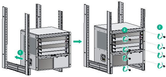
|
|
NOTE: If the screw holes in the mounting brackets cannot align with the cage nuts on the rack, verify that the bottom edge of the slide rail aligns with the middle of the narrowest metal area between holes and that the cage nuts are installed in the correct holes. |
Connecting the grounding cable
|
|
CAUTION: Before using the switch, connect the grounding cable correctly to guarantee lightning protection and anti-interference of the switch. |
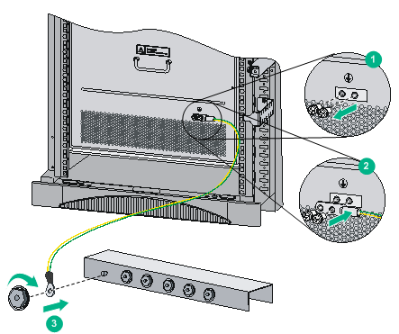
Connecting the grounding cable to a grounding strip
|
|
CAUTION: Connect the grounding cable to the earthing system in the equipment room. Do not connect it to a fire main or lightning rod. |
When a grounding strip is available at the installation site, connect the grounding cable through the grounding strip.
To connect the grounding cable:
1. Unpack the grounding cable.
Use the provided grounding cable (yellow-green grounding cable). The provided grounding cable is compliant with the NEBS standards.
2. Remove the grounding screws from the grounding holes at the rear of the chassis.
3. Use grounding screws to attach the two-hole grounding lug of the grounding cable to the chassis.
Figure 2-14 Connecting the grounding cable to a grounding strip
Grounding the switch through the AC power supply
|
|
CAUTION: · Make sure the AC power supply uses a three-wire cable with a protection wire, and the AC power cord is reliably grounded at the power distribution room or AC power supply transformer side. · Make sure the AC receptacle on the switch is correctly connected to the AC power supply. |
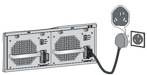
If the switch is AC powered and no grounding strip is available at the installation site, you can ground the switch through the AC power supply, as shown in Figure 2-15.
Figure 2-15 Grounding the switch through the AC power supply
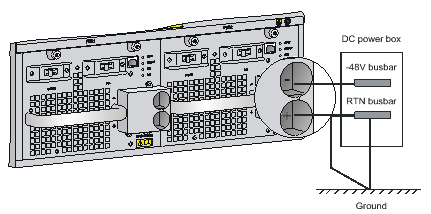
Grounding the switch through the RTN wire of a DC power supply
|
|
CAUTION: Make sure the RTN busbar in the equipment room is reliably grounded. |
If the switch is powered by a –48 VDC power supply and no grounding strip is available at the installation site, you can ground the switch through the return (RTN) wire of the DC power supply, as shown in Figure 2-16.
Figure 2-16 Grounding the switch through the RTN wire of the DC power supply