- Table of Contents
-
- H3C S7500E Switch Series Installation Guide-6W108
- 00-Preface
- 01-Chapter 1 Preparing for Installation
- 02-Chapter 2 Installing the Switch
- 03-Chapter 3 Installing FRUs
- 04-Chapter 4 Connecting Your Switch to the Network
- 05-Chapter 5 Replacement Procedures
- 06-Chapter 6 Troubleshooting
- 07-Appendix A Chassis Views and Technical Specifications
- 08-Appendix B FRUs and Compatibility Matrixes
- 09-Appendix C LEDs
- 10-Appendix D Cables
- 11-Appendix E Engineering Labels for Cables
- 12-Appendix F Cable Management
- Related Documents
-
| Title | Size | Download |
|---|---|---|
| 03-Chapter 3 Installing FRUs | 3.79 MB |
Installing the power supply system
Installing a power module adapter
(Optional) Setting up a PoE system
Connecting an external PoE power supply
(Optional) Installing a CF card on an MPU·
(Optional) Installing transceiver modules and network cables
Installing transceiver modules·
3 Installing FRUs
|
|
CAUTION: Do not install the switch, modules, and cables when the switch has power. |
There is no required order for installing FRUs. As a best practice, connect power cords after completing installing all required FRUs. Figures for the chassis and FRUs are for illustration only.
|
|
TIP: Keep the chassis and the component packages for future use. |
Attaching an ESD wrist strap
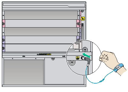
The S7500E series provides an ESD wrist strap. To minimize ESD damage to electronic components, wear an ESD wrist strap and ensure that it is reliably grounded when installing modules.
To use an ESD wrist strap:
1. Make sure the switch is reliably grounded. For how to ground your switch, see "Connecting the grounding cable."
2. Wear the wrist strap.
3. Tighten the wrist strap to keep good skin contact. Make sure the resistance reading between your body and the ground is between 1 and 10 megohms.
4. Insert the ESD wrist strap into the ESD socket on the switch chassis, or attach it to the grounding screw of the chassis with an alligator clip.
Figure 3-1 Attaching an ESD wrist strap (on an S7503E)
Installing cards
|
|
CAUTION: To avoid damaging the backplane, make sure the connectors on the card are not broken or blocked before installing a card in the chassis. |
|
|
IMPORTANT: · To ensure good ventilation, install a filler panel in an empty slot. · Before you install a card that has a protection box, remove the protection box from the card as follows: a. Loosen the captive screws that secure the card to the protection box. b. Pull the ejector levers of the card outwards. c. Pull the card out of the protection box. |
The installation procedures for MPUs and service modules are the same. Unless otherwise stated, MPUs and service modules are collectively referred to as "cards" in this document.
These cards are hot swappable.
To install a card:
1. Wear an ESD wrist strap, and make sure it has good skin contact and is reliably grounded. For more information, see "Attaching an ESD wrist strap."
2. Remove the filler panel (if any) from the slot to be used. Keep the filler panel secure for future use.
3. Rotate out the ejector levers on the card.
4. Hold the card by the front panel with one hand and support the card bottom with the other (do not touch its circuit). Slide the card steadily into the slot along the guide rails until you cannot push the card further.
5. Rotate in the ejector levers on the card.
6. Fasten the captive screws on the card.
Installing the power supply system
|
|
CAUTION: · In case of dual grid inputs, make sure the amplitude, phase, and frequency of the input voltage of the two grids are the same. · Provide a circuit breaker for each power module. · For good ventilation of the switch, make sure a filler panel is installed in an unused slot. · Do not install a power module adapter and a 3RU power module on the same switch. Make sure the power configurations are the same on the two power module slots. To use power module adapters, make sure the two power module slots have the same power module adapter and power module configurations. |
The switch uses 1+1 power redundancy and supports dual grid inputs. You can supply either AC or DC power for the switch. For information about the power modules available for the switch, see "Power modules."
For a switch that uses the PSR1400 or PSR2800 power modules, when the system power consumption is smaller than the power module capacity, you can use the following power configurations:
· PSR650C-12A or PSR650C-12D power modules, or LSQM1PWRSPA/LSQM1PWRSPB power module adapters and PSR650-A/PSR650-D power modules (not recommended) when the switch consumes less than 650 W and does not use PoE.
· LSQM1PWRSPB power module adapters and PSR650-A/PSR650-D/PSR1200-A/PSR1200-D power modules if you are to install more than two power modules in the switch.
To use a power module adapter, first install the power module adapter in the chassis, and then install power modules in the power module adapter.
Installing a power module adapter
|
|
CAUTION: Do not install power module adapters of different models on the same switch. |
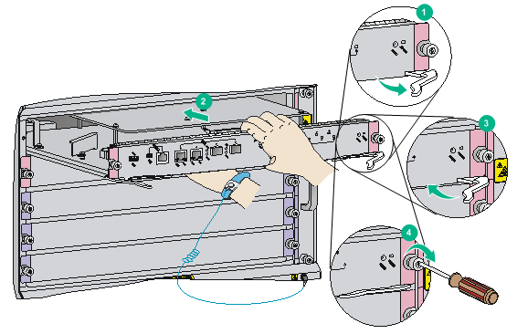
To install a power module adapter:
1. Wear an ESD wrist strap and make sure it makes good skin contact and is reliably grounded. For more information, see "Attaching an ESD wrist strap."
2. Unpack the power module adapter.
3. Holding the adapter handle with one hand and supporting the adapter bottom with the other, slide the adapter all the way into the chassis along the guide rails. Make sure the adapter is firmly seated in the chassis and has good contact with the backplane connectors.
To avoid damaging the power module adapter and the backplane connectors, remove the adapter, realign it with the chassis, and insert it again in case of misalignment.
4. Use a Phillips screwdriver to fasten the captive screws on the adapter to secure the adapter in the chassis.
If you cannot fasten the captive screws tightly, check the adapter installation.
Figure 3-3 Installing a power module adapter (LSQM1PWRSPB)
Installing a power module
|
|
CAUTION: · Before installing a power module, make sure the switch on the power module is in the OFF position. · Do not install power modules of different models on the same switch. · Make sure the outputs of the power modules to be installed can satisfy the requirements of the switch. · To avoid damaging a power module, move the power module by supporting its bottom rather than holding its handle. |
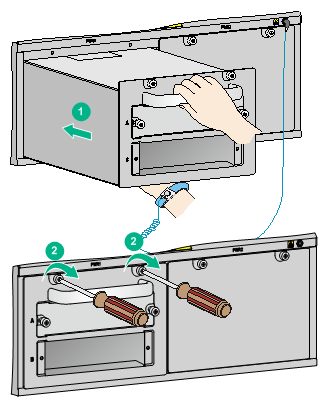
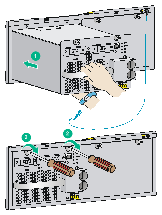
To install a power module:
1. Wear an ESD wrist strap and make sure it has good skin contact and is reliably grounded. For more information, see "Attaching an ESD wrist strap."
2. Remove the filler panel (if any) from the target slot.
Keep the filler panel secure for future use.
3. Unpack the power module, and verify that the power module model is correct.
4. Orient the power module correctly.
5. Grasping the handle of the module with one hand and supporting the module bottom with the other, align the power module with the slot. Push the power module along the guide rails into the slot. Make sure the power module has a good contact with the backplane.
To avoid damaging the power module and the backplane connectors, remove the power module, realign it with the slot, and insert it again in case of misalignment.
6. Use a Phillips screwdriver to fasten the captive screws on the power module to secure the power module in the chassis.
If the captive screws cannot be fastened tightly, do not fasten them forcibly. Check the power module installation.
Figure 3-4 Installing a power module (PSR1400-D)
Connecting the power cord
|
|
WARNING! Before connecting the power cord to a power module, make sure the switch on the power module is in the OFF position. |
Table 3-1 Power cord connection for the S7500E series
|
Model |
Power input (AC/DC) |
PoE support |
Description |
|
PSR320-A |
AC |
No |
|
|
PSR650-A |
|||
|
PSR650C-12A |
AC |
No |
|
|
PSR1200-A |
|||
|
PSR1400-A |
AC |
No |
|
|
PSR2500-12AHD |
AC |
No |
|
|
PSR2800-ACV |
AC |
Yes |
|
|
PSR6000-ACV |
AC |
Yes |
|
|
PSR320-D |
DC |
No |
|
|
PSR650-D |
|||
|
PSR650C-12D |
|||
|
PSR1200-D |
DC |
No |
|
|
PSR1400-D |
DC |
Yes |
Connecting the PSR1400-D/PSR1400-12D1/PSR2500-12D power module |
|
PSR1400-12D1 |
DC |
No |
|
|
PSR2500-12D |
DC |
No |
Typically 10A busbars are available in the equipment room but the PSR1200-A, PSR1400-A, PSR2500-12AHD, PSR2800-ACV, and PSR6000-ACV power modules require a 16A power cord (AC). You need to use a 16A busbar, and ensure that the AC power supply system can provide enough power. For the power cords used in different countries or regions, see "Power cords."
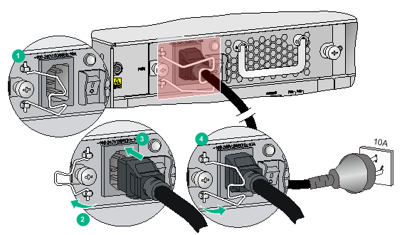
Connecting the PSR320-A/PSR650-A power module
1. Install a bail latch on the power module. Insert the two ends of the bail latch to the slots on the left of the power socket. Then pull the bail latch to the left.
2. Unpack the power cord, and verify the power cord model (both the PSR320-A and PSR650-A use a 10 A AC power cord).
3. Connect the power cord to the power socket, and ensure a good contact.
4. Pull the bail latch to the right to retain the power cord.
5. Connect the other end of the power cord to the AC power source.
Figure 3-5 Connecting the power cord for a PSR320-A/PSR650-A power module
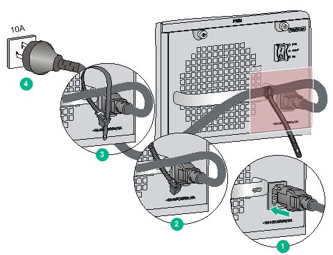
Connecting the PSR650C-12A/PSR1200-A power module
The power cord connection procedure is similar for the PSR650C-12A and PSR1200-A power modules. This procedure uses the PSR650C-12A power module as an example.
To connect the power cord:
1. Unpack the power cord, and verify the power cord model is correct.
The PSR650C-12A power module uses a 10A AC power cord. The PSR1200-A power module uses a 16A AC power cord.
2. Connect the power cord to the power socket, and ensure a good contact.
3. Use a cable tie to secure the power cord to the handle of the power module.
4. Connect the other end of the power cord to the AC power source.
Figure 3-6 Connecting the power cord for a PSR650C-12A power module
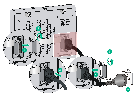
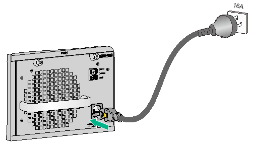
Connecting the PSR1400-A power module
1. Unpack the power cord, and verify the power cord model (the PSR1400-A uses a 16 A AC power cord).
2. Use a Phillips screwdriver to remove the screws from the power cord retainer suite and remove the right part of the retainer suite.
3. Connect the power cord to the power socket on the power module, and ensure a good contact.
4. Fasten the right part of the power cord retainer to lock the power cord.
5. Connect the other end of the power cord to the AC power source.
Figure 3-7 Connecting the power cord for a PSR1400-A power module
Connecting the PSR2500-12AHD power module
1. Unpack the power cord and make sure the power cord model is correct.
The PSR2500-12AHD power module uses a 16A AC power cord or a high-voltage DC power cord.
2. Connect the coupler end of the power cord into the power receptacle on the power module. Push the tab on the coupler to secure the coupler in position.
3. Connect the other end of the power cord to the AC power source.
Figure 3-8 Connecting a 16A AC power cord for a PSR2500-12AHD power module
Connecting the PSR2800-ACV power module
The PSR2800-ACV is a built-in power module with AC input and DC output. It can provide the switch with both system power and PoE power, which can be controlled through separate power switches. Before connecting the PSR2800-ACV power cord, make sure the system and PoE power switches are off.
The PSR2800-ACV provides two power sockets:
· One system power socket, as shown by callout 2 in Figure 3-9.
· One PoE power socket, as shown by callout 6 in Figure 3-9.
The methods for connecting the system power cord and PoE power cord are similar to connecting the PSR1400-A power cord. For more information, see "Connecting the PSR1400-A."
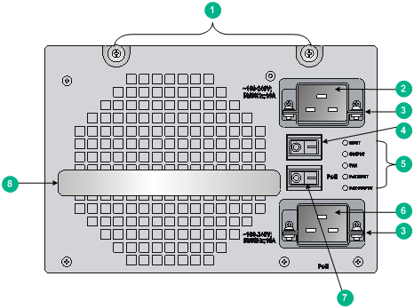
|
(1) Captive screw |
(2) System power socket |
(3) Power cord retainer suite |
|
(4) System power switch (O: off; —: on) |
(5) Power module status LED |
(6) PoE power socket |
|
(7) PoE power switch (O: off. —: on) |
(8) Power module handle |
|
Connecting the PSR6000-ACV power module
The PSR6000-ACV is a built-in power module with AC input and DC output. It can provide the switch with both system power and PoE power, which can be controlled through separate power switches. Before connecting the PSR6000-ACV power cord, make sure the system and PoE power switches are off.
The PSR6000-ACV provides four power sockets:
· One system power socket, as shown by callout 5 in Figure 3-10.
· Three PoE power sockets, as shown by callout 8 in Figure 3-10.
Connecting the system power cord is the same as connecting the PoE power cord. The following illustrates how to connect the system power cord.
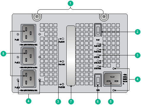
|
(1) Captive screw |
(2) PoE power switch (O: off; —: on) |
|
(3) Power module status LED |
(4) Fastening screw holes for the power cord retainer suite |
|
(5) System power socket |
(6) System power switch (O: off; —: on) |
|
(7) Power module handle |
(8) PoE power sockets |
To attach the power cord retainer suite:
1. Fasten the retainer suite to the plug of the power cord. Attach the left and right parts of the retainer suite to the power cord according to the relative positions shown in Figure 3-11.
2. Use a Phillips screwdriver to fasten the two parts of the retainer suite together.
Figure 3-11 Attaching the power cord retainer suite
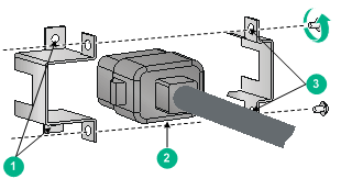
|
(1) Screw holes for connecting the retainer suite to the power module |
(2) Power cord plug |
|
(3) Screw holes for connecting the two parts of the retainer suite |
|
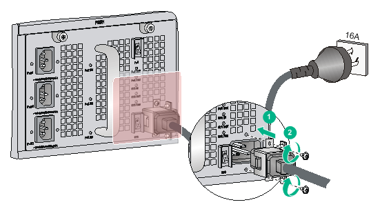
3. Connect the power cord into the power socket of the power module.
If you cannot align the screw holes on the retainer suite with those on the power module, pull the cable retainer suite outwards, rotate it by 180 degrees, and push it in until it is secured in place. Then, you can align the screw holes in the retainer suite with the screw holes in the power module.
4. Use a Phillips screwdriver to fasten the power cord retainer suite to the power module.
5. Connect the other end of the power cord to the AC power socket.
Figure 3-12 Connecting the AC power cord for a PSR6000-ACV power module
Connecting the PSR320-D/PSR650-D/PSR650C-12D power module
|
|
CAUTION: When connecting the DC power cord to the DC wiring terminals, make sure the circuit breaker at the power input end is off. |
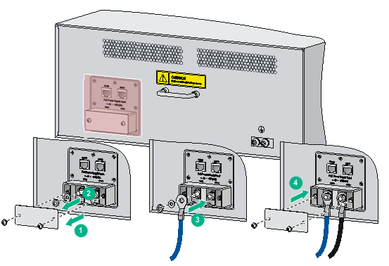
The procedures for connecting power cords for the PSR320-D, PSR650-D, and PSR650C-12D are similar. This section uses the PSR650-D as an example.
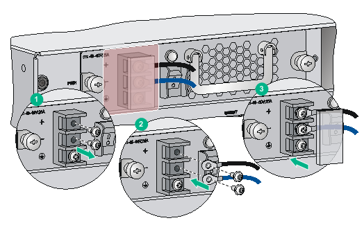
To connect the PSR650-D:
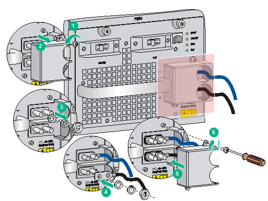
1. Remove the protection cover from the power module.
2. Loosen the captive screw on the wiring terminal with a Phillips screwdriver.
3. Connect the end of the blue DC power cord marked with – to the negative terminal (–) on the power module and fasten the screw.
4. Connect the end of the black DC power cord marked with + to the RTN (+) terminal on the power module and fasten the screw.
5. Put the protection cover on the wiring terminals.
6. Connect the other ends of the DC power cords to power source.
a. Connect the blue end to the negative terminal (–48V) on the power source.
b. Connect the black end to the positive terminal (RTN) on the power source.
Figure 3-13 Connecting the power cord for a PSR650-D power module
Connecting the PSR1200-D power module
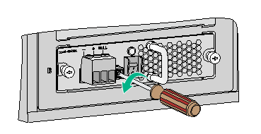
1. Loosen the captive screw that secures the terminal block plug to the chassis and remove the terminal block plug.
Figure 3-14 Removing the terminal block plug
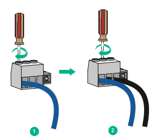
2. Unpack the DC power cord provided with the power module. Insert the wire marked with – to the negative terminal (–) on the terminal block and fasten the screw. Insert the wire marked with + to the positive terminal (+) and fasten the screw.
Figure 3-15 Inserting the DC power cord into the terminal block plug
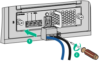
3. Correctly orient the terminal block plug and insert it into the power module. Use a Phillips screwdriver to fasten the screw on the plug.
Figure 3-16 Attaching the terminal block plug to the power module
4. Connect the other end of the DC power cord to the DC power source. Use a cable tie to secure the DC power cord to the nearby rack post.
Connecting the PSR1400-D/PSR1400-12D1/PSR2500-12D power module
|
|
CAUTION: When connecting the DC power cord to the DC wiring terminals, make sure the – end of the circuit breaker at the power input end is off. |
The power cord connection procedure is similar for the PSR1400-D, PSR1400-12D1, and PSR2500-12D power modules. The following uses a PSR1400-D power module as an example.
To connect the power cord for a PSR1400-D power module:
1. Loosen the captive screws on the protection cover with a Phillips screwdriver and remove the protection cover. There are two flat washers, one spring washer, and one M6 fastening nut from inside to outside on each wiring terminal.
2. Loosen the captive nuts on four wiring terminals with an M6 socket wrench, and remove the captive nut, spring washer, and one flat washer in turn from each wiring terminal.
3. Connect the end of the blue DC power cord marked with – to the negative terminal (–) on the power module.
4. Connect the end of the black DC power cord marked with + to the RTN (+) terminals on the power module.
5. Put the flat washer and spring washer on the wiring terminal in turn and screw up the captive nut with the M6 socket wrench. Repeat this step for the other three terminals.
6. Put the protection cover on the wiring terminals and faster the captive screws.
7. Connect the other ends of the DC power cords to power source.
a. Connect the blue end to the negative terminal (–48V) on the power source.
b. Connect the black end to the positive terminal (RTN) on the power source.
Figure 3-17 Connecting the power cord for a PSR1400-D power module
(Optional) Setting up a PoE system
|
|
CAUTION: If you do not use the PoE feature, verify that the PoE power switch on the power module is off. |
Requirements
Power over Ethernet (PoE) enables a power sourcing equipment (PSE) to supply power to powered devices (PDs) through power interfaces (PIs) over twisted pair cables. Commonly used PDs include IP telephones, APs, and web cameras.
The following PoE types are available:
· Type 1—Power delivered by a single port: 0 to 15.4 W; voltage range: 44 V to 57 V; maximum current: 350 mA. This PoE type provides power to classes 0 to 3 PDs.
· Type 2—Power delivered by a single port: 0 to 30 W, voltage range: 50 V to 57 V, maximum current: 600 mA. This PoE type provides power to classes 0 to 4 PDs.
To set up a PoE system, the following components are required:
· A switch that supports PoE.
· PSEs.
· An external PoE power supply.
· PoE power modules.
A switch that supports PoE
The S7502E, S7503E, S7503E-S, S7506E, S7506E-MF, S7506E-V, or S7510E switch.
PSEs
All cards require a PoE dual in-line memory module (DIMM) to provide the PoE function, except the LSQ3GV48SC0 (LSQM3GV48SC0), LSQ1GV48SD0 (LSQM1GV48SD0), LSQM4GV48SA0, and LSQM4GV48SC0. PoE DIMMs include the following types:
· 24-port PoE DIMM LSQM1POEDIMMS0.
· PoE master/subordinate DIMM LSBM1POEDIMMH.
For the compatibility between the two types of DIMMs and cards, see Table 3-2. For the installation of a PoE DIMM, see "Installing a PoE DIMM."
Table 3-2 Cards supporting PoE
|
Card model |
PI quantity |
DIMM |
PoE type |
|
LSQ1GV48SD0 |
48 |
Not required |
· Type 1 · Type 2 |
|
LSQ3GV48SC0 |
48 |
Not required |
· Type 1 · Type 2 |
|
LSQM4GV48SA0 |
48 |
Not required |
· Type 1 · Type 2 |
|
LSQM4GV48SC0 |
48 |
Not required |
· Type 1 · Type 2 |
|
LSQ1CGV24PSC0 |
24 |
LSQM1POEDIMMS0 |
Type 1 |
|
LSQ1GV24PSC0 |
24 |
LSQM1POEDIMMS0 |
Type 1 |
|
LSQ1GV24PSA0 |
24 |
LSQM1POEDIMMS0 |
Type 1 |
|
LSQ1FV48SA0 |
48 |
LSBM1POEDIMMH |
Type 1 |
|
LSQ1GV48SA0 |
48 |
LSBM1POEDIMMH |
Type 1 |
|
LSQ1GV48SC0 |
48 |
LSBM1POEDIMMH |
Type 1 |
|
LSQ1GV40PSC0 |
40 |
LSBM1POEDIMMH |
Type 1 |
|
|
NOTE: · The model of a card is LSQM-prefixed on the card package and LSQ-prefixed on the card panel. For example, LSQ1GV48SD0 and LSQM1GV48SD0 identify the same card. · Make sure the total PoE power required by all PDs connected to a PSE is not greater than the maximum PSE power. For more information about the maximum PSE power, see "Total power consumption." |
An external PoE power supply
An external PoE power supply is required only for the S7502E and S7503E-S switches because the two models use non-PoE power modules (PSR650-A/PSR650-D/PSR320-A/PSR320-D). The external PoE power supply must meet the following requirements:
· Output voltage—–46 to –57 VDC for type 1 PoE mode and –52 to –57 VDC for type 2 PoE mode.
· Maximum output current—40 A.
For how to connect an external PoE power supply, see "Connecting an external PoE power supply."
PoE power modules
PoE power modules are required only for the S7503E, S7506E, S7506E-MF, S7506E-V, and S7510E.
Table 3-3 PoE power modules
|
Power module |
Max. output power |
Power cords provided |
Power cord connection |
|
PSR1400-D |
6720 W |
No |
Connecting the PSR1400-D/PSR1400-12D1/PSR2500-12D power module |
|
PSR2800-ACV |
· 1150 W (110 V) · 1400 W (220 V) |
Yes |
|
|
PSR6000-ACV |
· One-line PoE input: ¡ 1200 W (110 V) ¡ 1800 W (220 V) · Two-line PoE input: ¡ 2400 W (110 V) ¡ 3600 W (220 V) · Three-line PoE input: ¡ 3600 W (110 V) ¡ 5300 W (220 V) |
Yes |
|
|
NOTE: · When the switch uses a PSR1400-D to supply PoE power, you can monitor the operating status of the external power supply through the PoE power monitoring port. The PoE power monitoring port is an RS-485 compliant port. You can select an RS-485 compliant connection method according to the monitoring port type. When you use a 48 VDC power source, you do not need to monitor the operating status of the external power supply. · When the switch uses a PSR6000-ACV to supply PoE power, make sure the input voltage for the system power input, PoE 1, PoE 2, and PoE 3 is the same. It can be either 110 VAC or 220 VAC. |
Installing a PoE DIMM
|
|
CAUTION: · Avoid touching the components on the PoE DIMM and PCB during installation and removal of a PoE DIMM. · If no PoE DIMM is in place or the module is not fully seated, the interface card cannot supply power, though other functions work well. |
The PoE DIMM slot is a reverse insertion prevention slot to help you identify the direction for installing a PoE DIMM.
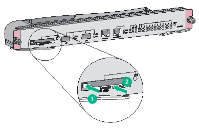
Installing the LSQM1POEDIMMS0
1. Wear an ESD wrist strap and make sure it has a good skin contact and is reliably grounded. For more information, see "Attaching an ESD wrist strap."
2. Make sure the card is sturdy. Then find the PoE DIMM slot (there is a master mark on the PCB under the slot) on the PCB.
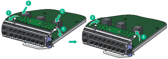
3. Pull the white clips on the two sides of the PoE DIMM slot outward, as shown by callout 1 in Figure 3-18.
4. Unpack the PoE DIMM, and align the golden plating of the PoE DIMM with the groove on the slot.
5. As shown by callout 2 in Figure 3-18, use your thumbs to press the edges of the PoE DIMM and push it along the guide rail into the slot until the white clips click into the grooves on the two sides of the PoE DIMM.
6. Verify that the clips lock the PoE DIMM.
Figure 3-18 Installing the LSQM1POEDIMMS0
Installing the LSBM1POEDIMMH
|
|
CAUTION: · Determine the PoE master DIMM and PoE subordinate DIMM before installation. For how to distinguish them, see Figure 3-19. · Install the master DIMM in the master DIMM slot (there is a "Master" mark on the PCB under the slot), and the subordinate DIMM in the subordinate DIMM slot (there is a "Slave" mark on the PCB under the slot). · The master and subordinate DIMMs must be used simultaneously. The PoE system operates correctly only when both of them are inserted in the correct slots. |
Figure 3-19 PoE master/subordinate DIMM
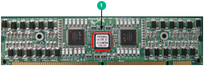
|
(1) A chip is on the master DIMM, but not on the subordinate DIMM. |
To install the LSBM1POEDIMMH:
1. Wear an ESD wrist strap and make sure it has a good skin contact and is reliably grounded. For more information, see "Attaching an ESD wrist strap."
2. Make sure the card is sturdy. Then find the PoE DIMM slot (there is a "Master" mark on the PCB under the slot) on the PCB.
3. Pull the white clips on the two sides of the PoE DIMM slot outward, as shown by callout 1 in Figure 3-18.
4. Unpack the master PoE DIMM, and align the golden plating of the PoE DIMM with the groove on the slot.
5. As shown by callout 2 in Figure 3-18, use your thumbs to press the edges of the master PoE DIMM and push it along the guide rail into the slot until the white clips click into the grooves on the two sides of the PoE DIMM.
6. Verify that the clips lock the master PoE DIMM.
7. Repeat steps 3 through 6 to install the subordinate DIMM in the subordinate DIMM slot (there is a "Slave" mark on the PCB under the slot).
Connecting an external PoE power supply
|
|
CAUTION: · To avoid damage to the switch, make sure you connect the negative ends of the power cords to negative terminals and positive ends to positive terminals. · To ensure steady operation of the switch, make sure the cross section of the cable is not less than 8.4 mm2 (0.01 in2) and the power cord can carry 50 A current. |
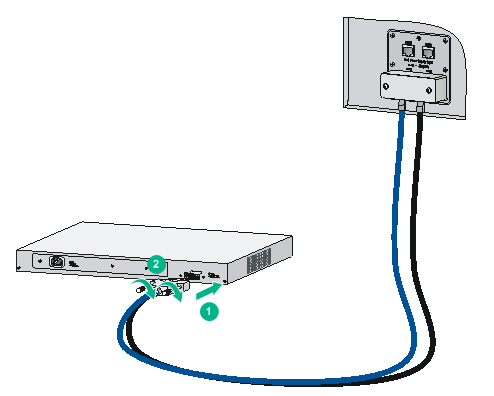
This section uses the RPS800-A as an example. As a best practice, order the power cord for the RPS800-A from H3C. For more information about RPS800-A, see RPS800-A User Manual.
Figure 3-20 Setting up a PoE system by using the RPS800-A
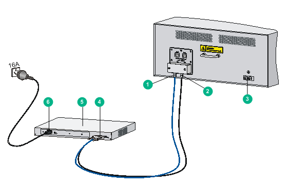
|
(1) NEG(–) terminal |
(2) RTN(+) terminal |
|
(3) Grounding point |
(4) DC input |
|
(5) RPS800-A |
(6) AC input |
To connect the RPS-800A to the switch:
1. Remove the blank panel covering the PoE port of the switch.
2. Remove the nuts and flat washers from the terminals.
3. Connect the ring terminal (with a – sign) on the power cord to the NEG(–) terminal on the PoE power supply socket, install the nut and washer, and then fasten the screw.
4. Connect the ring terminal (with a + sign) on the power cord to the RTN(+) terminal on the PoE power supply socket, install the flat washer, and then fasten the screw.
5. Install the blank panel to the PoE port.
Figure 3-21 Connecting the power cords to the switch
6. Connect the H2*7 connector of the PoE power cord to the DC output port of the RPS800-A, and then fasten the screw.
Figure 3-22 Connecting the power cords to the RPS800-A
7. Connect the female end of the AC power cord to the AC input port on the RPS800-A. Connect the male end of the AC power cord to the external power supply socket.
(Optional) Installing a CF card on an MPU
If you select an MPU that supports the CF card, you can install a CF card as needed.
To install a CF card:
1. Use a hard object to push the CF card eject button all the way into the slot, and make sure the button does not project from the panel.
2. Push the CF card all the way into the CF card slot so that it does not project. At the same time, the eject button projects.
Figure 3-23 Installing a CF card
(Optional) Installing transceiver modules and network cables
|
|
WARNING! Disconnected optical fibers or transceiver modules might emit invisible laser light. Do not stare into beams or view directly with optical instruments when the switch is operating. |
Installing transceiver modules
|
|
CAUTION: To avoid transceiver module or port damage, read this guide carefully before installing a transceiver module. |
|
|
CAUTION: · Be careful not to touch the golden plating on a transceiver module during the installation process. · Before installing a transceiver module, remove the optical fibers, if any, from it. · Make sure the transceiver module is aligned correctly with the target port before pushing it into the port. · Do not remove the dust plugs from a transceiver module until you are ready to connect optical fibers to it. |
Installing an XFP/SFP+/SFP/QSFP+/QSFP28 module
Two types of QSFP+ transceiver modules are available. One type uses a metal pull latch and the other type uses a plastic pull latch. The installation procedure is the same for the two types of QSFP+ transceiver modules.
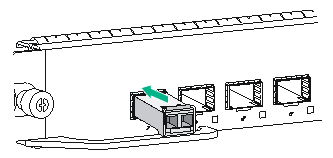
The installation procedure is similar for the XFP, SFP+, SFP, QSFP+, and QSFP28 transceiver modules. The following procedure installs an SFP+ transceiver module.
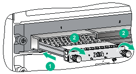
To install an SFP+ transceiver module:
1. Wear an ESD wrist strap and make sure it makes good skin contact and is reliably grounded. For more information, see "Attaching an ESD wrist strap."
2. Remove the dust plug from the target fiber port.
3. Unpack the SFP+ module. It comes with the bail latch catching the knob on the top of the transceiver module.
4. Grasp the transceiver module between your thumb and index finger. Align it with the fiber port and push it gently into the port until it snaps into place.
Transceiver modules and fiber ports have disorientation rejection designs. If you cannot insert a transceiver module easily into a port, the orientation might be wrong. Remove and reorient the transceiver module.
In case of limited space, you can gently push against the front face of the transceiver module instead of the two sides.
5. Connect optical fibers to the transceiver module. For the connection procedure, see "Connecting your switch to the network through optical fibers."
Figure 3-24 Installing an SFP+ module
Installing a CFP module
1. Wear an ESD wrist strap and make sure it makes good skin contact and is reliably grounded. For more information, see "Attaching an ESD wrist strap."
2. Remove the dust plug from the target fiber port.
3. Unpack the CFP module.
4. Correctly orient the transceiver module and align it with the fiber port. Push it gently into the port until you feel it snaps into place. See Figure 3-25.
Transceiver modules and fiber ports have disorientation rejection designs. If you cannot insert a transceiver module easily into a port, the orientation might be wrong. Remove and reorient the transceiver module.
5. Fasten the captive screws on the transceiver module to secure the module in place.
6. Connect optical fibers to the transceiver module. For the connection procedure, see "Connecting your switch to the network through optical fibers."
Figure 3-25 Installing a CFP module
Connecting network cables
|
|
CAUTION: When you connect a network cable, follow these restrictions and guidelines: · Make sure the two modular ends of a network cable are compatible with the ports into which they will be inserted. · Do not touch the golden plating on the two modular ends of a network cable. · To avoid network cable damage and signal loss, do not strain or tangle a network cable. · Before inserting a modular end of a network cable into a port, make sure the module aligns with the port correctly. · The bend radius of a network cable must be a minimum of 15 times the cable diameter. |
To connect ports over a short distance, use network cables as follows:
· SFP+ DAC cable—Connects two SFP+ ports over a short distance.
· QSFP+ DAC cable—Connects two QSFP+ ports over a short distance.
· QSFP+ to SFP+ DAC cable—Connects one QSFP+ port to four SFP+ ports over a short distance.
The network cables are hot swappable. The connection procedure is similar for these cables. The following procedure connects an SFP+ DAC cable.
To connect an SFP+ DAC cable:
1. Wear an ESD wrist strap and make sure it makes good skin contact and is reliably grounded. For more information, see "Attaching an ESD wrist strap."
2. Remove the dust plug from the target fiber port.
3. Unpack the cable.
4. As shown in Figure 3-26, align the module end of the cable with the fiber port and push it gently into the port until you feel it snaps into place.
Transceiver modules and fiber ports have disorientation rejection structures. If you cannot insert a transceiver module easily into a port, remove and reorient the transceiver module.
Figure 3-26 Connecting an SFP+ DAC cable
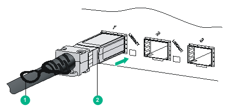
|
(1) Pull latch |
(2) Connector |
