- Table of Contents
-
- H3C S6890 Switch Series Configuration Examples-Release 27xx-6W100
- 01-Login Management Configuration Examples
- 02-RBAC Configuration Examples
- 03-Software Upgrade Examples
- 04-ISSU Configuration Examples
- 05-Software Patching Examples
- 06-Ethernet Link Aggregation Configuration Examples
- 07-Port Isolation Configuration Examples
- 08-Spanning Tree Configuration Examples
- 09-VLAN Configuration Examples
- 10-VLAN Tagging Configuration Examples
- 11-DHCP Snooping Configuration Examples
- 12-Cross-Subnet Dynamic IP Address Allocation Configuration Examples
- 13-GRE Tunnel Configuration Examples
- 14-GRE with OSPF Configuration Examples
- 15-OSPF Configuration Examples
- 16-IS-IS Configuration Examples
- 17-BGP Configuration Examples
- 18-Policy-Based Routing Configuration Examples
- 19-OSPFv3 Configuration Examples
- 20-IPv6 IS-IS Configuration Examples
- 21-Routing Policy Configuration Examples
- 22-IGMP Snooping Configuration Examples
- 23-IGMP Configuration Examples
- 24-Multicast VPN Configuration Examples
- 25-Basic MPLS Configuration Examples
- 26-MPLS L3VPN Configuration Examples
- 27-ACL Configuration Examples
- 28-Control Plane-Based QoS Policy Configuration Examples
- 29-Traffic Policing Configuration Examples
- 30-GTS and Rate Limiting Configuration Examples
- 31-Priority Mapping and Queue Scheduling Configuration Examples
- 32-Traffic Filtering Configuration Examples
- 33-AAA Configuration Examples
- 34-SSH Configuration Examples
- 35-IP Source Guard Configuration Examples
- 36-Ethernet OAM Configuration Examples
- 37-CFD Configuration Examples
- 38-DLDP Configuration Examples
- 39-VRRP Configuration Examples
- 40-BFD Configuration Examples
- 41-NTP Configuration Examples
- 42-SNMP Configuration Examples
- 43-NQA Configuration Examples
- 44-Mirroring Configuration Examples
- 45-sFlow Configuration Examples
- 46-FCoE Configuration Examples
- 47-OpenFlow Configuration Examples
- 48-MAC Address Table Configuration Examples
- 49-Static Multicast MAC Address Entry Configuration Examples
- 50-IP Unnumbered Configuration Examples
- 51-MVRP Configuration Examples
- 52-MCE Configuration Examples
- 53-Congestion Avoidance and Queue Scheduling Configuration Examples
- 54-Attack Protection Configuration Examples
- 55-Smart Link Configuration Examples
- 56-RRPP Configuration Examples
- 57-BGP Route Selection Configuration Examples
- 58-IS-IS Route Summarization Configuration Examples
- 59-IRF Configuration Examples
- 60-MPLS OAM Configuration Examples
- 61-MPLS TE Configuration Examples
- 62-VXLAN Configuration Examples
- 63-DRNI Configuration Examples
- 64-DRNI and EVPN Configuration Examples
- 65-VCF Fabric Configuration Examples
- Related Documents
-
| Title | Size | Download |
|---|---|---|
| 62-VXLAN Configuration Examples | 248.41 KB |
|
|
|
H3C S6890 Switch Series |
|
VXLAN Configuration Examples |
|
|
Document version: 6W100-20190628
Copyright © 2019 New H3C Technologies Co., Ltd. All rights reserved.
No part of this manual may be reproduced or transmitted in any form or by any means without prior written consent of New H3C Technologies Co., Ltd.
Except for the trademarks of New H3C Technologies Co., Ltd., any trademarks that may be mentioned in this document are the property of their respective owners.
The information in this document is subject to change without notice.
Contents
General restrictions and guidelines
Example: Configuring VXLAN Layer 2 forwarding
Configuring IP addresses for interfaces
Configuring a routing protocol on the transport network
Example: Configuring a centralized VXLAN IP gateway
Configuring IP addresses for interfaces
Configuring a routing protocol on the transport network
Configuring basic VXLAN settings
Configuring the centralized VXLAN IP gateway
Example: Configuring a centralized VXLAN IP gateway group
Configuring IP addresses for interfaces
Configuring a routing protocol on the transport network
Configuring basic VXLAN settings
Configuring centralized VXLAN IP gateway settings
Specifying the VTEP group as the gateway for access layer VTEPs
Introduction
This document provides Virtual eXtensible LAN (VXLAN) configuration examples. VXLAN is a MAC-in-UDP technology that provides Layer 2 connectivity between distant network sites across an IP network. VXLAN is typically used in data centers for multitenant services.
Prerequisites
This document is not restricted to specific software or hardware versions.
The configuration examples in this document were created and verified in a lab environment, and all the devices were started with the factory default configuration. When you are working on a live network, make sure you understand the potential impact of every command on your network.
This document assumes that you have basic knowledge of VXLAN.
General restrictions and guidelines
Before you can configure VXLANs, you must perform the following tasks:
1. Set the system operating mode to standard by using the system-working-mode standard command.
2. Save the configuration.
3. Reboot the device.
When you configure VXLAN, follow these restrictions and guidelines:
· If the device is a VTEP, enable Layer 2 or Layer 3 forwarding for VXLANs. If the device is a VXLAN IP gateway, enable Layer 3 forwarding for VXLANs.
· The VXLAN VSIs use broadcast traffic to learn remote MAC addresses. Do not use the flooding disable command to disable flooding for any VXLAN VSIs.
· A VXLAN IP gateway cannot have a lower-layer VXLAN IP gateway.
· VXLAN IP gateways are vulnerable to scanning attacks. To control the number of ARP packets on VXLAN IP gateways in an SDN network, set an appropriate ARP packet sending rate limit for the gateway VSI interfaces. For a gateway interface, the number of VXLAN tunnels multiplied by the ARP packet sending rate limit cannot exceed 4000.
Example: Configuring VXLAN Layer 2 forwarding
Network configuration
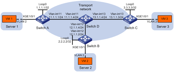
As shown in Figure 1:
· Configure VXLAN 10 as a unicast-mode VXLAN on Switch A, Switch B, and Switch C to provide Layer 2 connectivity for the VMs across the network sites.
· Manually establish VXLAN tunnels and assign the tunnels to VXLAN 10.
Analysis
To ensure that the switches in the transport network can reach one another, configure a routing protocol on the switches to advertise routes for interfaces, including the loopback interfaces. In this example, OSPF is used.
To assign Switch A, Switch B, and Switch C to a VXLAN network, create VXLAN tunnels on the switches and assign the tunnels to the VXLAN.
To assign the customer traffic of a VLAN to a VXLAN, you must perform the following tasks:
· Create an Ethernet service instance on the interface that receives the traffic.
· Configure the Ethernet service instance to match the VLAN.
· Map the Ethernet service instance to the VSI on which the VXLAN is created.
Software versions used
This configuration example was created and verified on S6890-CMW710-R2712.
Restrictions and guidelines
Execute the undo vxlan ip-forwarding command on each VTEP to enable Layer 2 forwarding for VXLANs on the VTEPs.
By default, interfaces on S6890 switches are disabled (in ADM or Administratively Down state). To have an interface operate, you must use the undo shutdown command to enable that interface.
Procedures
Configuring IP addresses for interfaces
# Configure IP addresses for interfaces on Switch A.
<SwitchA> system-view
[SwitchA] vlan 11
[SwitchA-vlan11] port ten-gigabitethernet 1/0/2
[SwitchA-vlan11] quit
[SwitchA] interface vlan-interface 11
[SwitchA-Vlan-interface11] ip address 11.1.1.1 24
[SwitchA-Vlan-interface11] quit
[SwitchA] interface loopback 0
[SwitchA-LoopBack0] ip address 1.1.1.1 32
[SwitchA-LoopBack0] quit
# Configure IP addresses for interfaces on other switches in the same way the IP addresses are configured on Switch A. (Details not shown.)
Configuring a routing protocol on the transport network
# Configure OSPF to advertise routes for Switch A.
[SwitchA] ospf 1 router-id 1.1.1.1
[SwitchA-ospf-1] area 0
[SwitchA-ospf-1-area-0.0.0.0] network 1.1.1.1 0.0.0.0
[SwitchA-ospf-1-area-0.0.0.0] network 11.1.1.0 0.0.0.255
[SwitchA-ospf-1-area-0.0.0.0] quit
[SwitchA-ospf-1] quit
# Configure OSPF to advertise routes for Switch B.
[SwitchB] ospf 1 router-id 2.2.2.2
[SwitchB-ospf-1] area 0
[SwitchB-ospf-1-area-0.0.0.0] network 2.2.2.2 0.0.0.0
[SwitchB-ospf-1-area-0.0.0.0] network 12.1.1.0 0.0.0.255
[SwitchB-ospf-1-area-0.0.0.0] quit
[SwitchB-ospf-1] quit
# Configure OSPF to advertise routes for Switch C.
[SwitchC] ospf 1 router-id 3.3.3.3
[SwitchC-ospf-1] area 0
[SwitchC-ospf-1-area-0.0.0.0] network 3.3.3.3 0.0.0.0
[SwitchC-ospf-1-area-0.0.0.0] network 13.1.1.0 0.0.0.255
[SwitchC-ospf-1-area-0.0.0.0] quit
[SwitchC-ospf-1] quit
# Configure OSPF to advertise routes for Switch D.
[SwitchD] ospf 1 router-id 4.4.4.4
[SwitchD-ospf-1] area 0
[SwitchD-ospf-1-area-0.0.0.0] network 4.4.4.4 0.0.0.0
[SwitchD-ospf-1-area-0.0.0.0] network 11.1.1.0 0.0.0.255
[SwitchD-ospf-1-area-0.0.0.0] network 12.1.1.0 0.0.0.255
[SwitchD-ospf-1-area-0.0.0.0] network 13.1.1.0 0.0.0.255
[SwitchD-ospf-1-area-0.0.0.0] quit
[SwitchD-ospf-1] quit
Configuring VXLAN settings
Configuring Switch A
# Enable L2VPN.
[SwitchA] l2vpn enable
# Enable Layer 2 forwarding for VXLANs.
[SwitchA] undo vxlan ip-forwarding
# Create VSI vpna and VXLAN 10.
[SwitchA] vsi vpna
[SwitchA-vsi-vpna] vxlan 10
[SwitchA-vsi-vpna-vxlan10] quit
[SwitchA-vsi-vpna] quit
# Create a VXLAN tunnel to Switch B. The tunnel interface name is Tunnel 1.
[SwitchA] interface tunnel 1 mode vxlan
[SwitchA-Tunnel1] source 1.1.1.1
[SwitchA-Tunnel1] destination 2.2.2.2
[SwitchA-Tunnel1] quit
# Create a VXLAN tunnel to Switch C. The tunnel interface name is Tunnel 2.
[SwitchA] interface tunnel 2 mode vxlan
[SwitchA-Tunnel2] source 1.1.1.1
[SwitchA-Tunnel2] destination 3.3.3.3
[SwitchA-Tunnel2] quit
# Assign Tunnel 1 and Tunnel 2 to VXLAN 10.
[SwitchA] vsi vpna
[SwitchA-vsi-vpna] vxlan 10
[SwitchA-vsi-vpna-vxlan10] tunnel 1
[SwitchA-vsi-vpna-vxlan10] tunnel 2
[SwitchA-vsi-vpna-vxlan10] quit
[SwitchA-vsi-vpna] quit
# On Ten-GigabitEthernet 1/0/1, configure Ethernet service instance 1000 to match VLAN 2.
[SwitchA] interface ten-gigabitethernet 1/0/1
[SwitchA-Ten-GigabitEthernet1/0/1] service-instance 1000
[SwitchA-Ten-GigabitEthernet1/0/1-srv1000] encapsulation s-vid 2
# Map Ethernet service instance 1000 to VSI vpna.
[SwitchA-Ten-GigabitEthernet1/0/1-srv1000] xconnect vsi vpna
[SwitchA-Ten-GigabitEthernet1/0/1-srv1000] quit
[SwitchA-Ten-GigabitEthernet1/0/1] quit
Configuring Switch B
# Enable L2VPN.
[SwitchB] l2vpn enable
# Enable Layer 2 forwarding for VXLANs.
[SwitchB] undo vxlan ip-forwarding
# Create VSI vpna and VXLAN 10.
[SwitchB] vsi vpna
[SwitchB-vsi-vpna] vxlan 10
[SwitchB-vsi-vpna-vxlan10] quit
[SwitchB-vsi-vpna] quit
# Create a VXLAN tunnel to Switch A. The tunnel interface name is Tunnel 1.
[SwitchB] interface tunnel 1 mode vxlan
[SwitchB-Tunnel1] source 2.2.2.2
[SwitchB-Tunnel1] destination 1.1.1.1
[SwitchB-Tunnel1] quit
# Create a VXLAN tunnel to Switch C. The tunnel interface name is Tunnel 2.
[SwitchB] interface tunnel 2 mode vxlan
[SwitchB-Tunnel2] source 2.2.2.2
[SwitchB-Tunnel2] destination 3.3.3.3
[SwitchB-Tunnel2] quit
# Assign Tunnel 1 and Tunnel 2 to VXLAN 10.
[SwitchB] vsi vpna
[SwitchB-vsi-vpna] vxlan 10
[SwitchB-vsi-vpna-vxlan10] tunnel 1
[SwitchB-vsi-vpna-vxlan10] tunnel 2
[SwitchB-vsi-vpna-vxlan10] quit
[SwitchB-vsi-vpna] quit
# On Ten-GigabitEthernet 1/0/1, configure Ethernet service instance 1000 to match VLAN 2.
[SwitchB] interface ten-gigabitethernet 1/0/1
[SwitchB-Ten-GigabitEthernet1/0/1] service-instance 1000
[SwitchB-Ten-GigabitEthernet1/0/1-srv1000] encapsulation s-vid 2
# Map Ethernet service instance 1000 to VSI vpna.
[SwitchB-Ten-GigabitEthernet1/0/1-srv1000] xconnect vsi vpna
[SwitchB-Ten-GigabitEthernet1/0/1-srv1000] quit
[SwitchB-Ten-GigabitEthernet1/0/1] quit
Configuring Switch C
# Enable L2VPN.
[SwitchC] l2vpn enable
# Enable Layer 2 forwarding for VXLANs.
[SwitchC] undo vxlan ip-forwarding
# Create VSI vpna and VXLAN 10.
[SwitchC] vsi vpna
[SwitchC-vsi-vpna] vxlan 10
[SwitchC-vsi-vpna-vxlan10] quit
[SwitchC-vsi-vpna] quit
# Create a VXLAN tunnel to Switch A. The tunnel interface name is Tunnel 1.
[SwitchC] interface tunnel 1 mode vxlan
[SwitchC-Tunnel1] source 3.3.3.3
[SwitchC-Tunnel1] destination 1.1.1.1
[SwitchC-Tunnel1] quit
# Create a VXLAN tunnel to Switch B. The tunnel interface name is Tunnel 2.
[SwitchC] interface tunnel 2 mode vxlan
[SwitchC-Tunnel2] source 3.3.3.3
[SwitchC-Tunnel2] destination 2.2.2.2
[SwitchC-Tunnel2] quit
# Assign Tunnel 1 and Tunnel 2 to VXLAN 10.
[SwitchC] vsi vpna
[SwitchC-vsi-vpna] vxlan 10
[SwitchC-vsi-vpna-vxlan10] tunnel 1
[SwitchC-vsi-vpna-vxlan10] tunnel 2
[SwitchC-vsi-vpna-vxlan10] quit
[SwitchC-vsi-vpna] quit
# On Ten-GigabitEthernet 1/0/1, configure Ethernet service instance 1000 to match VLAN 2.
[SwitchC] interface ten-gigabitethernet 1/0/1
[SwitchC-Ten-GigabitEthernet1/0/1] service-instance 1000
[SwitchC-Ten-GigabitEthernet1/0/1-srv1000] encapsulation s-vid 2
# Map Ethernet service instance 1000 to VSI vpna.
[SwitchC-Ten-GigabitEthernet1/0/1-srv1000] xconnect vsi vpna
[SwitchC-Ten-GigabitEthernet1/0/1-srv1000] quit
[SwitchC-Ten-GigabitEthernet1/0/1] quit
Verifying the configuration
1. Verify the VXLAN settings on the VTEPs. This example uses Switch A.
# Verify that the VXLAN tunnel interfaces on the VTEP are in up state.
[SwitchA] display interface tunnel
Tunnel1
Current state: UP
Line protocol state: UP
Description: Tunnel1 Interface
Bandwidth: 64 kbps
Maximum transmission unit: 1464
Internet protocol processing: Disabled
Last clearing of counters: Never
Tunnel source 1.1.1.1, destination 2.2.2.2
Tunnel protocol/transport UDP_VXLAN/IP
Last 300 seconds input rate: 0 bytes/sec, 0 bits/sec, 0 packets/sec
Last 300 seconds output rate: 0 bytes/sec, 0 bits/sec, 0 packets/sec
Input: 0 packets, 0 bytes, 0 drops
Output: 0 packets, 0 bytes, 0 drops
Tunnel2
Current state: UP
Line protocol state: UP
Description: Tunnel2 Interface
Bandwidth: 64 kbps
Maximum transmission unit: 1464
Internet protocol processing: Disabled
Last clearing of counters: Never
Tunnel source 1.1.1.1, destination 3.3.3.3
Tunnel protocol/transport UDP_VXLAN/IP
Last 300 seconds input rate: 0 bytes/sec, 0 bits/sec, 0 packets/sec
Last 300 seconds output rate: 0 bytes/sec, 0 bits/sec, 0 packets/sec
Input: 0 packets, 0 bytes, 0 drops
Output: 0 packets, 0 bytes, 0 drops
# Verify that the VXLAN tunnels have been assigned to the VXLAN, and the VXLAN tunnels and Ethernet service instances are in up state.
[SwitchA] display l2vpn vsi verbose
VSI Name: vpna
VSI Index : 0
VSI State : Up
MTU : 1500
Bandwidth : Unlimited
Broadcast Restrain : Unlimited
Multicast Restrain : Unlimited
Unknown Unicast Restrain: Unlimited
MAC Learning : Enabled
MAC Table Limit : -
MAC Learning rate : -
Drop Unknown : -
Flooding : Enabled
Statistics : Disabled
VXLAN ID : 10
Tunnels:
Tunnel Name Link ID State Type Flood proxy
Tunnel1 0x5000001 Up Manual Disabled
Tunnel2 0x5000002 Up Manual Disabled
ACs:
AC Link ID State Type
XGE1/0/1 srv1000 0 Up Manual
# Verify that the VTEP has learned the MAC addresses of remote VMs.
[SwitchA] display l2vpn mac-address
MAC Address State VSI Name Link ID/Name Aging
cc3e-5f9c-6cdb Dynamic vpna Tunnel1 Aging
cc3e-5f9c-23dc Dynamic vpna Tunnel2 Aging
--- 2 mac address(es) found ---
2. Verify that VM 1, VM 2, and VM 3 can ping each other. (Details not shown.)
Configuration files
· Switch A:
#
undo vxlan ip-forwarding
#
ospf 1 router-id 1.1.1.1
area 0.0.0.0
network 1.1.1.1 0.0.0.0
network 11.1.1.0 0.0.0.255
#
vlan 2
#
vlan 11
#
l2vpn enable
#
vsi vpna
vxlan 10
tunnel 1
tunnel 2
#
interface LoopBack0
ip address 1.1.1.1 255.255.255.255
#
interface Vlan-interface11
ip address 11.1.1.1 255.255.255.0
#
interface Ten-GigabitEthernet1/0/1
port link-mode bridge
service-instance 1000
encapsulation s-vid 2
xconnect vsi vpna
#
interface Ten-GigabitEthernet1/0/2
port link-mode bridge
port access vlan 11
#
interface Tunnel1 mode vxlan
source 1.1.1.1
destination 2.2.2.2
#
interface Tunnel2 mode vxlan
source 1.1.1.1
destination 3.3.3.3
#
return
· Switch B:
#
undo vxlan ip-forwarding
#
ospf 1 router-id 2.2.2.2
area 0.0.0.0
network 2.2.2.2 0.0.0.0
network 12.1.1.0 0.0.0.255
#
vlan 2
#
vlan 12
#
l2vpn enable
#
vsi vpna
vxlan 10
tunnel 1
tunnel 2
#
interface LoopBack0
ip address 2.2.2.2 255.255.255.255
#
interface Vlan-interface12
ip address 12.1.1.2 255.255.255.0
#
interface Ten-GigabitEthernet1/0/1
port link-mode bridge
service-instance 1000
encapsulation s-vid 2
xconnect vsi vpna
#
interface Ten-GigabitEthernet1/0/2
port link-mode bridge
port access vlan 12
#
interface Tunnel1 mode vxlan
source 2.2.2.2
destination 1.1.1.1
#
interface Tunnel2 mode vxlan
source 2.2.2.2
destination 3.3.3.3
#
return
· Switch C:
#
undo vxlan ip-forwarding
#
ospf 1 router-id 3.3.3.3
area 0.0.0.0
network 3.3.3.3 0.0.0.0
network 13.1.1.0 0.0.0.255
#
vlan 2
#
vlan 13
#
l2vpn enable
#
vsi vpna
vxlan 10
tunnel 1
tunnel 2
#
interface LoopBack0
ip address 3.3.3.3 255.255.255.255
#
interface Vlan-interface13
ip address 13.1.1.3 255.255.255.0
#
interface Ten-GigabitEthernet1/0/1
port link-mode bridge
service-instance 1000
encapsulation s-vid 2
xconnect vsi vpna
#
interface Ten-GigabitEthernet1/0/2
port link-mode bridge
port access vlan 13
#
interface Tunnel1 mode vxlan
source 3.3.3.3
destination 1.1.1.1
#
interface Tunnel2 mode vxlan
source 3.3.3.3
destination 2.2.2.2
#
return
· Switch D:
#
ospf 1 router-id 4.4.4.4
area 0.0.0.0
network 4.4.4.4 0.0.0.0
network 11.1.1.0 0.0.0.255
network 12.1.1.0 0.0.0.255
network 13.1.1.0 0.0.0.255
#
vlan 11
#
vlan 12
#
vlan 13
#
interface LoopBack0
ip address 4.4.4.4 255.255.255.255
#
interface Vlan-interface11
ip address 11.1.1.4 255.255.255.0
#
interface Vlan-interface12
ip address 12.1.1.4 255.255.255.0
#
interface Vlan-interface13
ip address 13.1.1.4 255.255.255.0
#
interface Ten-GigabitEthernet1/0/1
port link-mode bridge
port access vlan 11
#
interface Ten-GigabitEthernet1/0/2
port link-mode bridge
port access vlan 12
#
interface Ten-GigabitEthernet1/0/3
port link-mode bridge
port access vlan 13
#
return
Example: Configuring a centralized VXLAN IP gateway
Network configuration
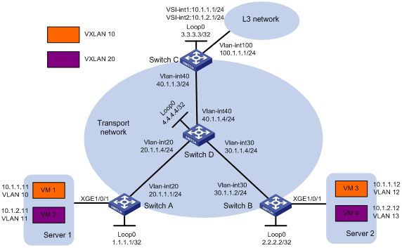
As shown in Figure 2:
· Configure VXLAN 10 and VXLAN 20 as unicast-mode VXLANs on Switch A, Switch B, and Switch C.
· Manually establish VXLAN tunnels and assign the tunnels to VXLAN 10 or VXLAN 20. Make sure VM 1 and VM 3 belong to VXLAN 10 and VM 2 and VM 4 belong to VXLAN 20.
· Configure a centralized VXLAN IP gateway on Switch C to provide gateway services for VXLAN 10 and VXLAN 20.
Analysis
To ensure that the switches in the transport network can reach one another, configure a routing protocol on the switches to advertise routes for interfaces, including the loopback interfaces. In this example, OSPF is used.
To assign Switch A, Switch B, and Switch C to VXLANs, create VXLAN tunnels on the switches and assign the tunnels to the VXLANs.
To assign the customer traffic of a VLAN to a VXLAN on Switch A or Switch B, you must perform the following tasks:
· Create an Ethernet service instance on the interface that receives the traffic.
· Configure the Ethernet service instance to match the VLAN.
· Map the Ethernet service instance to the VSI on which the VXLAN is created.
For Switch C to provide centralized VXLAN IP gateway services for VXLANs, you must perform the following tasks:
· Create a VSI interface for each VXLAN on the switch.
· Assign an IP address to each VSI interface.
· Specify the VSI interfaces as the gateway interfaces for VXLANs.
For Layer 3 nodes in the transport network to reach the VMs, configure a routing protocol on Switch C to advertise routes for VSI interfaces and VLAN-interface 100. In this example, OSPF is used.
Software versions used
This configuration example was created and verified on S6890 CMW710-R2712.
Restrictions and guidelines
By default, interfaces on S6890 switches are disabled (in ADM or Administratively Down state). To have an interface operate, you must use the undo shutdown command to enable that interface.
Procedures
Configuring IP addresses for interfaces
# Configure IP addresses for interfaces on Switch A.
<SwitchA> system-view
[SwitchA] vlan 20
[SwitchA-vlan20] port ten-gigabitethernet 1/0/2
[SwitchA-vlan20] quit
[SwitchA] interface vlan-interface 20
[SwitchA-Vlan-interface20] ip address 20.1.1.1 24
[SwitchA-Vlan-interface20] quit
[SwitchA] interface loopback 0
[SwitchA-LoopBack0] ip address 1.1.1.1 32
# Configure IP addresses for interfaces on other devices in the same way the IP addresses are configured on Switch A. (Details not shown.)
Configuring a routing protocol on the transport network
# Configure OSPF to advertise routes for Switch A.
[SwitchA] ospf 1 router-id 1.1.1.1
[SwitchA-ospf-1] area 0
[SwitchA-ospf-1-area-0.0.0.0] network 1.1.1.1 0.0.0.0
[SwitchA-ospf-1-area-0.0.0.0] network 20.1.1.0 0.0.0.255
[SwitchA-ospf-1-area-0.0.0.0] quit
[SwitchA-ospf-1] quit
# Configure OSPF to advertise routes for Switch B.
[SwitchB] ospf 1 router-id 2.2.2.2
[SwitchB-ospf-1] area 0
[SwitchB-ospf-1-area-0.0.0.0] network 2.2.2.2 0.0.0.0
[SwitchB-ospf-1-area-0.0.0.0] network 30.1.1.0 0.0.0.255
[SwitchB-ospf-1-area-0.0.0.0] quit
[SwitchB-ospf-1] quit
# Configure OSPF to advertise routes for Switch C.
[SwitchC] ospf 1 router-id 3.3.3.3
[SwitchC-ospf-1] area 0
[SwitchC-ospf-1-area-0.0.0.0] network 3.3.3.3 0.0.0.0
[SwitchC-ospf-1-area-0.0.0.0] network 40.1.1.0 0.0.0.255
[SwitchC-ospf-1-area-0.0.0.0] quit
[SwitchC-ospf-1] quit
# Configure OSPF to advertise routes for Switch D.
[SwitchD] ospf 1 router-id 4.4.4.4
[SwitchD-ospf-1] area 0
[SwitchD-ospf-1-area-0.0.0.0] network 4.4.4.4 0.0.0.0
[SwitchD-ospf-1-area-0.0.0.0] network 20.1.1.0 0.0.0.255
[SwitchD-ospf-1-area-0.0.0.0] network 30.1.1.0 0.0.0.255
[SwitchD-ospf-1-area-0.0.0.0] network 40.1.1.0 0.0.0.255
[SwitchD-ospf-1-area-0.0.0.0] quit
[SwitchD-ospf-1] quit
Configuring basic VXLAN settings
Configuring Switch A
# Enable L2VPN.
[SwitchA] l2vpn enable
# Enable Layer 2 forwarding for VXLANs.
[SwitchA] undo vxlan ip-forwarding
# Create VSI vpna and VXLAN 10.
[SwitchA] vsi vpna
[SwitchA-vsi-vpna] vxlan 10
[SwitchA-vsi-vpna-vxlan10] quit
[SwitchA-vsi-vpna] quit
# Create VSI vpnb and VXLAN 20.
[SwitchA] vsi vpnb
[SwitchA-vsi-vpnb] vxlan 20
[SwitchA-vsi-vpnb-vxlan10] quit
[SwitchA-vsi-vpnb] quit
# Create a VXLAN tunnel to Switch B. The tunnel interface name is Tunnel 1.
[SwitchA] interface tunnel 1 mode vxlan
[SwitchA-Tunnel1] source 1.1.1.1
[SwitchA-Tunnel1] destination 2.2.2.2
[SwitchA-Tunnel1] quit
# Create a VXLAN tunnel to Switch C. The tunnel interface name is Tunnel 2.
[SwitchA] interface tunnel 2 mode vxlan
[SwitchA-Tunnel2] source 1.1.1.1
[SwitchA-Tunnel2] destination 3.3.3.3
[SwitchA-Tunnel2] quit
# Assign Tunnel 1 and Tunnel 2 to VXLAN 10.
[SwitchA] vsi vpna
[SwitchA-vsi-vpna] vxlan 10
[SwitchA-vsi-vpna-vxlan10] tunnel 1
[SwitchA-vsi-vpna-vxlan10] tunnel 2
[SwitchA-vsi-vpna-vxlan10] quit
[SwitchA-vsi-vpna] quit
# Assign Tunnel 1 and Tunnel 2 to VXLAN 20.
[SwitchA] vsi vpnb
[SwitchA-vsi-vpnb] vxlan 20
[SwitchA-vsi-vpnb-vxlan20] tunnel 1
[SwitchA-vsi-vpnb-vxlan20] tunnel 2
[SwitchA-vsi-vpnb-vxlan20] quit
[SwitchA-vsi-vpnb] quit
# On Ten-GigabitEthernet 1/0/1, configure Ethernet service instance 1000 to match VLAN 10.
[SwitchA] interface ten-gigabitethernet 1/0/1
[SwitchA-Ten-GigabitEthernet1/0/1] service-instance 1000
[SwitchA-Ten-GigabitEthernet1/0/1-srv1000] encapsulation s-vid 10
# Map Ethernet service instance 1000 to VSI vpna.
[SwitchA-Ten-GigabitEthernet1/0/1-srv1000] xconnect vsi vpna
[SwitchA-Ten-GigabitEthernet1/0/1-srv1000] quit
# On Ten-GigabitEthernet 1/0/1, configure Ethernet service instance 2000 to match VLAN 11.
[SwitchA-Ten-GigabitEthernet1/0/1] service-instance 2000
[SwitchA-Ten-GigabitEthernet1/0/1-srv2000] encapsulation s-vid 11
# Map Ethernet service instance 2000 to VSI vpnb.
[SwitchA-Ten-GigabitEthernet1/0/1-srv2000] xconnect vsi vpnb
[SwitchA-Ten-GigabitEthernet1/0/1-srv2000] quit
[SwitchA-Ten-GigabitEthernet1/0/1] quit
Configuring Switch B
# Enable L2VPN.
[SwitchB] l2vpn enable
# Enable Layer 2 forwarding for VXLANs.
[SwitchB] undo vxlan ip-forwarding
# Create VSI vpna and VXLAN 10.
[SwitchB] vsi vpna
[SwitchB-vsi-vpna] vxlan 10
[SwitchB-vsi-vpna-vxlan10] quit
[SwitchB-vsi-vpna] quit
# Create VSI vpnb and VXLAN 20.
[SwitchB] vsi vpnb
[SwitchB-vsi-vpnb] vxlan 20
[SwitchB-vsi-vpnb-vxlan10] quit
[SwitchB-vsi-vpnb] quit
# Create a VXLAN tunnel to Switch A. The tunnel interface name is Tunnel 1.
[SwitchB] interface tunnel 1 mode vxlan
[SwitchB-Tunnel1] source 2.2.2.2
[SwitchB-Tunnel1] destination 1.1.1.1
[SwitchB-Tunnel1] quit
# Create a VXLAN tunnel to Switch C. The tunnel interface name is Tunnel 2.
[SwitchB] interface tunnel 2 mode vxlan
[SwitchB-Tunnel2] source 2.2.2.2
[SwitchB-Tunnel2] destination 3.3.3.3
[SwitchB-Tunnel2] quit
# Assign Tunnel 1 and Tunnel 2 to VXLAN 10.
[SwitchB] vsi vpna
[SwitchB-vsi-vpna] vxlan 10
[SwitchB-vsi-vpna-vxlan10] tunnel 1
[SwitchB-vsi-vpna-vxlan10] tunnel 2
[SwitchB-vsi-vpna-vxlan10] quit
[SwitchB-vsi-vpna] quit
# Assign Tunnel 1 and Tunnel 2 to VXLAN 20.
[SwitchB] vsi vpnb
[SwitchB-vsi-vpnb] vxlan 20
[SwitchB-vsi-vpnb-vxlan20] tunnel 1
[SwitchB-vsi-vpnb-vxlan20] tunnel 2
[SwitchB-vsi-vpnb-vxlan20] quit
[SwitchB-vsi-vpnb] quit
# On Ten-GigabitEthernet 1/0/1, configure Ethernet service instance 1000 to match VLAN 12.
[SwitchB] interface ten-gigabitethernet 1/0/1
[SwitchB-Ten-GigabitEthernet1/0/1] service-instance 1000
[SwitchB-Ten-GigabitEthernet1/0/1-srv1000] encapsulation s-vid 12
# Map Ethernet service instance 1000 to VSI vpna.
[SwitchB-Ten-GigabitEthernet1/0/1-srv1000] xconnect vsi vpna
[SwitchB-Ten-GigabitEthernet1/0/1-srv1000] quit
# On Ten-GigabitEthernet 1/0/1, configure Ethernet service instance 2000 to match VLAN 13.
[SwitchB-Ten-GigabitEthernet1/0/1] service-instance 2000
[SwitchB-Ten-GigabitEthernet1/0/1-srv2000] encapsulation s-vid 13
# Map Ethernet service instance 2000 to VSI vpnb.
[SwitchB-Ten-GigabitEthernet1/0/1-srv2000] xconnect vsi vpnb
[SwitchB-Ten-GigabitEthernet1/0/1-srv2000] quit
[SwitchB-Ten-GigabitEthernet1/0/1] quit
Configuring Switch C
# Enable L2VPN.
[SwitchC] l2vpn enable
# Create VSI vpna and VXLAN 10.
[SwitchC] vsi vpna
[SwitchC-vsi-vpna] vxlan 10
[SwitchC-vsi-vpna-vxlan10] quit
[SwitchC-vsi-vpna] quit
# Create VSI vpnb and VXLAN 20.
[SwitchC] vsi vpnb
[SwitchC-vsi-vpnb] vxlan 20
[SwitchC-vsi-vpnb-vxlan10] quit
[SwitchC-vsi-vpnb] quit
# Create a VXLAN tunnel to Switch A. The tunnel interface name is Tunnel 1.
[SwitchC] interface tunnel 1 mode vxlan
[SwitchC-Tunnel1] source 3.3.3.3
[SwitchC-Tunnel1] destination 1.1.1.1
[SwitchC-Tunnel1] quit
# Create a VXLAN tunnel to Switch B. The tunnel interface name is Tunnel 2.
[SwitchC] interface tunnel 2 mode vxlan
[SwitchC-Tunnel2] source 3.3.3.3
[SwitchC-Tunnel2] destination 2.2.2.2
[SwitchC-Tunnel2] quit
# Assign Tunnel 1 and Tunnel 2 to VXLAN 10.
[SwitchC] vsi vpna
[SwitchC-vsi-vpna] vxlan 10
[SwitchC-vsi-vpna-vxlan10] tunnel 1
[SwitchC-vsi-vpna-vxlan10] tunnel 2
[SwitchC-vsi-vpna-vxlan10] quit
[SwitchC-vsi-vpna] quit
# Assign Tunnel 1 and Tunnel 2 to VXLAN 20.
[SwitchC] vsi vpnb
[SwitchC-vsi-vpnb] vxlan 20
[SwitchC-vsi-vpnb-vxlan20] tunnel 1
[SwitchC-vsi-vpnb-vxlan20] tunnel 2
[SwitchC-vsi-vpnb-vxlan20] quit
[SwitchC-vsi-vpnb] quit
Configuring the centralized VXLAN IP gateway
# Create VSI-interface 1 and assign the interface an IP address. The IP address will be used as the gateway address for VXLAN 10.
[SwitchC] interface vsi-interface 1
[SwitchC-Vsi-interface1] ip address 10.1.1.1 255.255.255.0
[SwitchC-Vsi-interface1] quit
# Specify VSI-interface 1 as the gateway interface for VSI vpna.
[SwitchC] vsi vpna
[SwitchC-vsi-vpna] gateway vsi-interface 1
[SwitchC-vsi-vpna] quit
# Create VSI-interface 2 and assign the interface an IP address. The IP address will be used as the gateway address for VXLAN 20.
[SwitchC] interface vsi-interface 2
[SwitchC-Vsi-interface2] ip address 10.1.2.1 255.255.255.0
[SwitchC-Vsi-interface2] quit
# Specify VSI-interface 2 as the gateway interface for VSI vpnb.
[SwitchC] vsi vpnb
[SwitchC-vsi-vpnb] gateway vsi-interface 2
[SwitchC-vsi-vpnb] quit
# Configure OSPF to advertise routes for the VSI interfaces and VLAN-interface 100.
[SwitchC] ospf 2 router-id 3.3.3.3
[SwitchC-ospf-2] area 0
[SwitchC-ospf-2-area-0.0.0.0] network 10.1.1.0 0.0.0.255
[SwitchC-ospf-2-area-0.0.0.0] network 10.1.2.0 0.0.0.255
[SwitchC-ospf-2-area-0.0.0.0] network 100.1.1.0 0.0.0.255
[SwitchC-ospf-2-area-0.0.0.0] quit
[SwitchC-ospf-2] quit
Verifying the configuration
1. Verify the VXLAN settings on the VTEPs. This example uses Switch A.
# Verify that the VXLAN tunnel interfaces are in up state.
[SwitchA] display interface tunnel
Tunnel1
Current state: UP
Line protocol state: UP
Description: Tunnel1 Interface
Bandwidth: 64 kbps
Maximum transmission unit: 1464
Internet protocol processing: Disabled
Last clearing of counters: Never
Tunnel source 1.1.1.1, destination 2.2.2.2
Tunnel protocol/transport UDP_VXLAN/IP
Last 300 seconds input rate: 0 bytes/sec, 0 bits/sec, 0 packets/sec
Last 300 seconds output rate: 0 bytes/sec, 0 bits/sec, 0 packets/sec
Input: 0 packets, 0 bytes, 0 drops
Output: 0 packets, 0 bytes, 0 drops
Tunnel2
Current state: UP
Line protocol state: UP
Description: Tunnel2 Interface
Bandwidth: 64 kbps
Maximum transmission unit: 1464
Internet protocol processing: Disabled
Last clearing of counters: Never
Tunnel source 1.1.1.1, destination 3.3.3.3
Tunnel protocol/transport UDP_VXLAN/IP
Last 300 seconds input rate: 0 bytes/sec, 0 bits/sec, 0 packets/sec
Last 300 seconds output rate: 0 bytes/sec, 0 bits/sec, 0 packets/sec
Input: 0 packets, 0 bytes, 0 drops
Output: 0 packets, 0 bytes, 0 drops
# Verify that the VXLAN tunnels have been assigned to their respective VXLANs, and the VXLAN tunnels and Ethernet service instances are in up state.
[SwitchA] display l2vpn vsi verbose
VSI Name: vpna
VSI Index : 0
VSI State : Up
MTU : 1500
Bandwidth : Unlimited
Broadcast Restrain : Unlimited
Multicast Restrain : Unlimited
Unknown Unicast Restrain: Unlimited
MAC Learning : Enabled
MAC Table Limit : -
MAC Learning rate : -
Drop Unknown : -
Flooding : Enabled
Statistics : Disabled
VXLAN ID : 10
Tunnels:
Tunnel Name Link ID State Type Flood proxy
Tunnel1 0x5000001 Up Manual Disabled
Tunnel2 0x5000002 Up Manual Disabled
ACs:
AC Link ID State Type
XGE1/0/1 srv1000 0 Up Manual
VSI Name: vpnb
VSI Index : 1
VSI State : Up
MTU : 1500
Bandwidth : Unlimited
Broadcast Restrain : Unlimited
Multicast Restrain : Unlimited
Unknown Unicast Restrain: Unlimited
MAC Learning : Enabled
MAC Table Limit : -
MAC Learning rate : -
Drop Unknown : -
Flooding : Enabled
Statistics : Disabled
VXLAN ID : 20
Tunnels:
Tunnel Name Link ID State Type Flood proxy
Tunnel1 0x5000001 Up Manual Disabled
Tunnel2 0x5000002 Up Manual Disabled
ACs:
AC Link ID State Type
XGE1/0/1 srv2000 0 Up Manual
2. Verify the configuration on the VXLAN IP gateway:
# Verify that the VXLAN tunnel interfaces are in up state.
[SwitchC] display interface tunnel
Tunnel1
Current state: UP
Line protocol state: UP
Description: Tunnel1 Interface
Bandwidth: 64 kbps
Maximum transmission unit: 1464
Internet protocol processing: Disabled
Last clearing of counters: Never
Tunnel source 3.3.3.3, destination 1.1.1.1
Tunnel protocol/transport UDP_VXLAN/IP
Last 300 seconds input rate: 0 bytes/sec, 0 bits/sec, 0 packets/sec
Last 300 seconds output rate: 0 bytes/sec, 0 bits/sec, 0 packets/sec
Input: 0 packets, 0 bytes, 0 drops
Output: 0 packets, 0 bytes, 0 drops
Tunnel2
Current state: UP
Line protocol state: UP
Description: Tunnel2 Interface
Bandwidth: 64 kbps
Maximum transmission unit: 1464
Internet protocol processing: Disabled
Last clearing of counters: Never
Tunnel source 3.3.3.3, destination 2.2.2.2
Tunnel protocol/transport UDP_VXLAN/IP
Last 300 seconds input rate: 0 bytes/sec, 0 bits/sec, 0 packets/sec
Last 300 seconds output rate: 0 bytes/sec, 0 bits/sec, 0 packets/sec
Input: 0 packets, 0 bytes, 0 drops
Output: 0 packets, 0 bytes, 0 drops
# Verify that the VSI interfaces are in up state.
[SwitchC] display interface vsi-interface
Vsi-interface1
Current state: UP
Line protocol state: UP
Description: Vsi-interface1 Interface
Bandwidth: 1000000 kbps
Maximum transmission unit: 1500
Internet Address: 10.1.1.1/24 (primary)
IP packet frame type: Ethernet II, hardware address: 0000-fc00-458d
IPv6 packet frame type: Ethernet II, hardware address: 0000-fc00-458d
Physical: Unknown, baudrate: 1000000 kbps
Last clearing of counters: Never
Last 300 seconds input rate: 0 bytes/sec, 0 bits/sec, 0 packets/sec
Last 300 seconds output rate: 0 bytes/sec, 0 bits/sec, 0 packets/sec
Input: 0 packets, 0 bytes, 0 drops
Output: 0 packets, 0 bytes, 0 drops
Vsi-interface2
Current state: UP
Line protocol state: UP
Description: Vsi-interface2 Interface
Bandwidth: 1000000 kbps
Maximum transmission unit: 1500
Internet Address: 10.1.2.1/24 (primary)
IP packet frame type: Ethernet II, hardware address: 0000-fc00-458d
IPv6 packet frame type: Ethernet II, hardware address: 0000-fc00-458d
Physical: Unknown, baudrate: 1000000 kbps
Last clearing of counters: Never
Last 300 seconds input rate: 0 bytes/sec, 0 bits/sec, 0 packets/sec
Last 300 seconds output rate: 0 bytes/sec, 0 bits/sec, 0 packets/sec
Input: 0 packets, 0 bytes, 0 drops
Output: 0 packets, 0 bytes, 0 drops
# Verify that the VXLAN tunnels have been assigned to VXLANs 10 and 20, VSI-interface 1 is the gateway interface of VSI vpna, and VSI-interface 2 is the gateway interface of VSI vpnb.
[SwitchC] display l2vpn vsi verbose
VSI Name: vpna
VSI Index : 0
VSI State : Up
MTU : 1500
Bandwidth : Unlimited
Broadcast Restrain : Unlimited
Multicast Restrain : Unlimited
Unknown Unicast Restrain: Unlimited
MAC Learning : Enabled
MAC Table Limit : -
MAC Learning rate : -
Drop Unknown : -
Flooding : Enabled
Statistics : Disabled
Gateway interface : VSI-interface 1
VXLAN ID : 10
Tunnels:
Tunnel Name Link ID State Type Flooding proxy
Tunnel1 0x5000002 Up Manual Disabled
Tunnel2 0x5000003 Up Manual Disabled
VSI Name: vpnb
VSI Index : 1
VSI State : Up
MTU : 1500
Bandwidth : Unlimited
Broadcast Restrain : Unlimited
Multicast Restrain : Unlimited
Unknown Unicast Restrain: Unlimited
MAC Learning : Enabled
MAC Table Limit : -
MAC Learning rate : -
Drop Unknown : -
Flooding : Enabled
Statistics : Disabled
Gateway interface : VSI-interface 2
VXLAN ID : 20
Tunnels:
Tunnel Name Link ID State Type Flooding proxy
Tunnel1 0x5000002 Up Manual Disabled
Tunnel2 0x5000003 Up Manual Disabled
# Verify that Switch C has created ARP entries for the VMs.
[SwitchC] display arp
Type: S-Static D-Dynamic O-Openflow R-Rule M-Multiport I-Invalid
IP address MAC address VLAN/VSI Interface/Link ID Aging Type
10.1.1.11 0000-1234-0001 N/A Tunnel1 20 D
10.1.1.12 0000-1234-0002 N/A Tunnel2 19 D
# Verify that Switch C has created FIB entries for the VMs.
[SwitchC] display fib 10.1.1.11
Destination count: 1 FIB entry count: 1
Flag:
U:Useable G:Gateway H:Host B:Blackhole D:Dynamic S:Static
R:Relay F:FRR
Destination/Mask Nexthop Flag OutInterface/Token Label
10.1.1.11/32 10.1.1.11 UH Vsi1 Null
3. Verify the network connectivity for VMs:
# Verify that VM 1, VM 2, VM 3, and VM 4 can ping each other. (Details not shown.)
# Verify that VM 1, VM 2, VM 3, VM 4, and VLAN-interface 100 (100.1.1.1) on Switch C can ping each other. (Details not shown.)
Configuration files
· Switch A:
#
undo vxlan ip-forwarding
#
ospf 1 router-id 1.1.1.1
area 0.0.0.0
network 1.1.1.1 0.0.0.0
network 20.1.1.0 0.0.0.255
#
vlan 20
#
l2vpn enable
#
vsi vpna
vxlan 10
tunnel 1
tunnel 2
#
vsi vpnb
vxlan 20
tunnel 1
tunnel 2
#
interface LoopBack0
ip address 1.1.1.1 255.255.255.255
#
interface Vlan-interface20
ip address 20.1.1.1 255.255.255.0
#
interface Ten-GigabitEthernet1/0/1
port link-mode bridge
service-instance 1000
encapsulation s-vid 10
xconnect vsi vpna
service-instance 2000
encapsulation s-vid 11
xconnect vsi vpnb
#
interface Ten-GigabitEthernet1/0/2
port link-mode bridge
port access vlan 20
#
interface Tunnel1 mode vxlan
source 1.1.1.1
destination 2.2.2.2
#
interface Tunnel2 mode vxlan
source 1.1.1.1
destination 3.3.3.3
· Switch B:
#
undo vxlan ip-forwarding
#
ospf 1 router-id 2.2.2.2
area 0.0.0.0
network 2.2.2.2 0.0.0.0
network 30.1.1.0 0.0.0.255
#
vlan 30
#
l2vpn enable
#
vsi vpna
vxlan 10
tunnel 1
tunnel 2
#
vsi vpnb
vxlan 20
tunnel 1
tunnel 2
#
interface LoopBack0
ip address 2.2.2.2 255.255.255.255
#
interface Vlan-interface30
ip address 30.1.1.2 255.255.255.0
#
interface Ten-GigabitEthernet1/0/1
port link-mode bridge
service-instance 1000
encapsulation s-vid 12
xconnect vsi vpna
service-instance 2000
encapsulation s-vid 13
xconnect vsi vpnb
#
interface Ten-GigabitEthernet1/0/2
port link-mode bridge
port access vlan 30
#
interface Tunnel1 mode vxlan
source 2.2.2.2
destination 1.1.1.1
#
interface Tunnel2 mode vxlan
source 2.2.2.2
destination 3.3.3.3
· Switch C:
#
ospf 1 router-id 3.3.3.3
area 0.0.0.0
network 3.3.3.3 0.0.0.0
network 40.1.1.0 0.0.0.255
#
ospf 2 router-id 3.3.3.3
area 0.0.0.0
network 10.1.1.0 0.0.0.255
network 10.1.2.0 0.0.0.255
network 100.1.1.0 0.0.0.255
#
vlan 40
#
vlan 100
#
l2vpn enable
#
vsi vpna
gateway vsi-interface 1
vxlan 10
tunnel 1
tunnel 2
#
vsi vpnb
gateway vsi-interface 2
vxlan 20
tunnel 1
tunnel 2
#
interface LoopBack0
ip address 3.3.3.3 255.255.255.255
#
interface Vlan-interface40
ip address 40.1.1.3 255.255.255.0
#
interface Vlan-interface100
ip address 100.1.1.1 255.255.255.0
#
interface Ten-GigabitEthernet1/0/2
port link-mode bridge
port access vlan 40
#
interface Ten-GigabitEthernet1/0/3
port link-mode bridge
port access vlan 100
#
interface Vsi-interface1
ip address 10.1.1.1 255.255.255.0
#
interface Vsi-interface2
ip address 10.1.2.1 255.255.255.0
#
interface Tunnel1 mode vxlan
source 3.3.3.3
destination 1.1.1.1
#
interface Tunnel2 mode vxlan
source 3.3.3.3
destination 2.2.2.2
#
return
· Switch D:
#
ospf 1 router-id 4.4.4.4
area 0.0.0.0
network 4.4.4.4 0.0.0.0
network 20.1.1.0 0.0.0.255
network 30.1.1.0 0.0.0.255
network 40.1.1.0 0.0.0.255
#
vlan 20
#
vlan 30
#
vlan 40
#
interface LoopBack0
ip address 4.4.4.4 255.255.255.255
#
interface Vlan-interface20
ip address 20.1.1.4 255.255.255.0
#
interface Vlan-interface30
ip address 30.1.1.4 255.255.255.0
#
interface Vlan-interface40
ip address 40.1.1.4 255.255.255.0
#
interface Ten-GigabitEthernet1/0/1
port link-mode bridge
port access vlan 20
#
interface Ten-GigabitEthernet1/0/2
port link-mode bridge
port access vlan 30
#
interface Ten-GigabitEthernet1/0/3
port link-mode bridge
port access vlan 40
#
return
Example: Configuring a centralized VXLAN IP gateway group
Network configuration
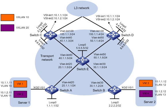
As shown in Figure 3:
· Configure VXLAN 10 and VXLAN 20 as unicast-mode VXLANs on Switch A, Switch B, Switch C, and Switch D.
· Manually establish VXLAN tunnels and assign the tunnels to VXLAN 10 or VXLAN 20. Make sure VM 1 and VM 3 belong to VXLAN 10 and VM 2 and VM 4 belong to VXLAN 20.
· Assign Switch C and Switch D to a VTEP group to provide gateway services for VXLAN 10 and VXLAN 20.
Analysis
To ensure that the switches in the transport network can reach one another, configure a routing protocol on the switches to advertise routes for interfaces, including the loopback interfaces. In this example, OSPF is used.
To assign Switch A, Switch B, Switch C, and Switch D to VXLANs, create VXLAN tunnels on the switches and assign the tunnels to the VXLANs.
To assign the customer traffic of a VLAN to a VXLAN on Switch A or Switch B, you must perform the following tasks:
· Create an Ethernet service instance on the interface that receives the traffic.
· Configure the Ethernet service instance to match the VLAN.
· Map the Ethernet service instance to the VSI on which the VXLAN is created.
For Switch C and Switch D to act as centralized VXLAN IP gateways, you must perform the following tasks:
· Create a VSI interface for each VXLAN on the switches.
· Assign an IP address to each VSI interface.
· Specify the VSI interfaces as the gateway interfaces for VXLANs.
For Layer 3 nodes in the transport network to reach the VMs, configure a routing protocol on Switch C and Switch D to advertise routes for VSI interfaces and VLAN-interface 100. In this example, OSPF is used.
Software versions used
This configuration example was created and verified on S6890 CMW710-R2712.
Restrictions and guidelines
When you configure a VTEP group, follow these restrictions and guidelines:
· You must create the same VSI interface on all VTEPs in the VTEP group and assign the same IP and MAC addresses to the VSI interface.
· The MAC address of a VSI interface is used only in ARP responses. The bridge MAC address of the device is used as the source MAC address for Layer 3 packets to be forwarded. To prevent ARP entries from being aged out, configure the VSI interface to send gratuitous ARP packets periodically.
· Execute the vtep group group-ip member local member-ip command on each member VTEP in the VTEP group. The IP address specified by the member-ip argument must already exist on the VTEP. You must configure a routing protocol to advertise the IP address to the transport network.
· Member VTEPs in a VTEP group cannot use the group IP address or share an IP address.
· Execute the vtep group group-ip member remote member-ip&<1-8> command on each member VTEP in the VTEP group. Specify the member IP addresses of all the other VTEPs in the group for the command.
· By default, interfaces on S6890 switches are disabled (in ADM or Administratively Down state). To have an interface operate, you must use the undo shutdown command to enable that interface.
Procedures
Configuring IP addresses for interfaces
# Configure IP addresses for interfaces on Switch A.
<SwitchA> system-view
[SwitchA] vlan 20
[SwitchA-vlan20] port ten-gigabitethernet 1/0/2
[SwitchA-vlan20] quit
[SwitchA] interface vlan-interface 20
[SwitchA-Vlan-interface20] ip address 20.1.1.1 24
[SwitchA-Vlan-interface20] quit
[SwitchA] interface loopback 0
[SwitchA-LoopBack0] ip address 1.1.1.1 32
# Configure IP addresses for interfaces on other devices in the same way the IP addresses are configured on Switch A. (Details not shown.)
Configuring a routing protocol on the transport network
# Configure OSPF to advertise routes for Switch A.
[SwitchA] ospf 1 router-id 1.1.1.1
[SwitchA-ospf-1] area 0
[SwitchA-ospf-1-area-0.0.0.0] network 1.1.1.1 0.0.0.0
[SwitchA-ospf-1-area-0.0.0.0] network 20.1.1.0 0.0.0.255
[SwitchA-ospf-1-area-0.0.0.0] quit
[SwitchA-ospf-1] quit
# Configure OSPF to advertise routes for Switch B.
[SwitchB] ospf 1 router-id 2.2.2.2
[SwitchB-ospf-1] area 0
[SwitchB-ospf-1-area-0.0.0.0] network 2.2.2.2 0.0.0.0
[SwitchB-ospf-1-area-0.0.0.0] network 30.1.1.0 0.0.0.255
[SwitchB-ospf-1-area-0.0.0.0] quit
[SwitchB-ospf-1] quit
# Configure OSPF to advertise routes for Switch C.
[SwitchC] ospf 1 router-id 3.3.3.3
[SwitchC-ospf-1] area 0
[SwitchC-ospf-1-area-0.0.0.0] network 3.3.3.3 0.0.0.0
[SwitchC-ospf-1-area-0.0.0.0] network 8.8.8.8 0.0.0.0
[SwitchC-ospf-1-area-0.0.0.0] network 40.1.1.0 0.0.0.255
[SwitchC-ospf-1-area-0.0.0.0] quit
[SwitchC-ospf-1] quit
# Configure OSPF to advertise routes for Switch D.
[SwitchD] ospf 1 router-id 4.4.4.4
[SwitchD-ospf-1] area 0
[SwitchD-ospf-1-area-0.0.0.0] network 4.4.4.4 0.0.0.0
[SwitchD-ospf-1-area-0.0.0.0] network 8.8.8.8 0.0.0.0
[SwitchD-ospf-1-area-0.0.0.0] network 50.1.1.0 0.0.0.255
[SwitchD-ospf-1-area-0.0.0.0] quit
[SwitchD-ospf-1] quit
# Configure OSPF to advertise routes for Switch E.
[SwitchE] ospf 1 router-id 5.5.5.5
[SwitchE-ospf-1] area 0
[SwitchE-ospf-1-area-0.0.0.0] network 5.5.5.5 0.0.0.0
[SwitchE-ospf-1-area-0.0.0.0] network 20.1.1.0 0.0.0.255
[SwitchE-ospf-1-area-0.0.0.0] network 30.1.1.0 0.0.0.255
[SwitchE-ospf-1-area-0.0.0.0] network 40.1.1.0 0.0.0.255
[SwitchE-ospf-1-area-0.0.0.0] network 50.1.1.0 0.0.0.255
[SwitchE-ospf-1-area-0.0.0.0] quit
[SwitchE-ospf-1] quit
Configuring basic VXLAN settings
Configuring Switch A
# Enable L2VPN.
[SwitchA] l2vpn enable
# Enable Layer 2 forwarding for VXLANs.
[SwitchA] undo vxlan ip-forwarding
# Create VSI vpna and VXLAN 10.
[SwitchA] vsi vpna
[SwitchA-vsi-vpna] vxlan 10
[SwitchA-vsi-vpna-vxlan10] quit
[SwitchA-vsi-vpna] quit
# Create VSI vpnb and VXLAN 20.
[SwitchA] vsi vpnb
[SwitchA-vsi-vpnb] vxlan 20
[SwitchA-vsi-vpnb-vxlan10] quit
[SwitchA-vsi-vpnb] quit
# Create a VXLAN tunnel to the VTEP group. The tunnel interface name is Tunnel 1.
[SwitchA] interface tunnel 1 mode vxlan
[SwitchA-Tunnel1] source 1.1.1.1
[SwitchA-Tunnel1] destination 8.8.8.8
[SwitchA-Tunnel1] quit
# Create a VXLAN tunnel to Switch B. The tunnel interface name is Tunnel 2.
[SwitchA] interface tunnel 2 mode vxlan
[SwitchA-Tunnel2] source 1.1.1.1
[SwitchA-Tunnel2] destination 2.2.2.2
[SwitchA-Tunnel2] quit
# Assign Tunnel 1 and Tunnel 2 to VXLAN 10.
[SwitchA] vsi vpna
[SwitchA-vsi-vpna] vxlan 10
[SwitchA-vsi-vpna-vxlan10] tunnel 1
[SwitchA-vsi-vpna-vxlan10] tunnel 2
[SwitchA-vsi-vpna-vxlan10] quit
[SwitchA-vsi-vpna] quit
# Assign Tunnel 1 and Tunnel 2 to VXLAN 20.
[SwitchA] vsi vpnb
[SwitchA-vsi-vpnb] vxlan 20
[SwitchA-vsi-vpnb-vxlan20] tunnel 1
[SwitchA-vsi-vpnb-vxlan20] tunnel 2
[SwitchA-vsi-vpnb-vxlan20] quit
[SwitchA-vsi-vpnb] quit
# On Ten-GigabitEthernet 1/0/1, configure Ethernet service instance 1000 to match VLAN 10.
[SwitchA] interface ten-gigabitethernet 1/0/1
[SwitchA-Ten-GigabitEthernet1/0/1] service-instance 1000
[SwitchA-Ten-GigabitEthernet1/0/1-srv1000] encapsulation s-vid 10
# Map Ethernet service instance 1000 to VSI vpna.
[SwitchA-Ten-GigabitEthernet1/0/1-srv1000] xconnect vsi vpna
[SwitchA-Ten-GigabitEthernet1/0/1-srv1000] quit
# On Ten-GigabitEthernet 1/0/1, configure Ethernet service instance 2000 to match VLAN 11.
[SwitchA-Ten-GigabitEthernet1/0/1] service-instance 2000
[SwitchA-Ten-GigabitEthernet1/0/1-srv2000] encapsulation s-vid 11
# Map Ethernet service instance 2000 to VSI vpnb.
[SwitchA-Ten-GigabitEthernet1/0/1-srv2000] xconnect vsi vpnb
[SwitchA-Ten-GigabitEthernet1/0/1-srv2000] quit
[SwitchA-Ten-GigabitEthernet1/0/1] quit
Configuring Switch B
# Enable L2VPN.
[SwitchB] l2vpn enable
# Enable Layer 2 forwarding for VXLANs.
[SwitchB] undo vxlan ip-forwarding
# Create VSI vpna and VXLAN 10.
[SwitchB] vsi vpna
[SwitchB-vsi-vpna] vxlan 10
[SwitchB-vsi-vpna-vxlan10] quit
[SwitchB-vsi-vpna] quit
# Create VSI vpnb and VXLAN 20.
[SwitchB] vsi vpnb
[SwitchB-vsi-vpnb] vxlan 20
[SwitchB-vsi-vpnb-vxlan10] quit
[SwitchB-vsi-vpnb] quit
# Create a VXLAN tunnel to the VTEP group. The tunnel interface name is Tunnel 1.
[SwitchB] interface tunnel 1 mode vxlan
[SwitchB-Tunnel1] source 2.2.2.2
[SwitchB-Tunnel1] destination 8.8.8.8
[SwitchB-Tunnel1] quit
# Create a VXLAN tunnel to Switch A. The tunnel interface name is Tunnel 2.
[SwitchB] interface tunnel 2 mode vxlan
[SwitchB-Tunnel2] source 2.2.2.2
[SwitchB-Tunnel2] destination 1.1.1.1
[SwitchB-Tunnel2] quit
# Assign Tunnel 1 and Tunnel 2 to VXLAN 10.
[SwitchB] vsi vpna
[SwitchB-vsi-vpna] vxlan 10
[SwitchB-vsi-vpna-vxlan10] tunnel 1
[SwitchB-vsi-vpna-vxlan10] tunnel 2
[SwitchB-vsi-vpna-vxlan10] quit
[SwitchB-vsi-vpna] quit
# Assign Tunnel 1 and Tunnel 2 to VXLAN 20.
[SwitchB] vsi vpnb
[SwitchB-vsi-vpnb] vxlan 20
[SwitchB-vsi-vpnb-vxlan20] tunnel 1
[SwitchB-vsi-vpnb-vxlan20] tunnel 2
[SwitchB-vsi-vpnb-vxlan20] quit
[SwitchB-vsi-vpnb] quit
# On Ten-GigabitEthernet 1/0/1, configure Ethernet service instance 1000 to match VLAN 12.
[SwitchB] interface ten-gigabitethernet 1/0/1
[SwitchB-Ten-GigabitEthernet1/0/1] service-instance 1000
[SwitchB-Ten-GigabitEthernet1/0/1-srv1000] encapsulation s-vid 12
# Map Ethernet service instance 1000 to VSI vpna.
[SwitchB-Ten-GigabitEthernet1/0/1-srv1000] xconnect vsi vpna
[SwitchB-Ten-GigabitEthernet1/0/1-srv1000] quit
# On Ten-GigabitEthernet 1/0/1, configure Ethernet service instance 2000 to match VLAN 13.
[SwitchB-Ten-GigabitEthernet1/0/1] service-instance 2000
[SwitchB-Ten-GigabitEthernet1/0/1-srv2000] encapsulation s-vid 13
# Map Ethernet service instance 2000 to VSI vpnb.
[SwitchB-Ten-GigabitEthernet1/0/1-srv2000] xconnect vsi vpnb
[SwitchB-Ten-GigabitEthernet1/0/1-srv2000] quit
[SwitchB-Ten-GigabitEthernet1/0/1] quit
Configuring Switch C
# Enable L2VPN.
[SwitchC] l2vpn enable
# Create VSI vpna and VXLAN 10.
[SwitchC] vsi vpna
[SwitchC-vsi-vpna] vxlan 10
[SwitchC-vsi-vpna-vxlan10] quit
[SwitchC-vsi-vpna] quit
# Create VSI vpnb and VXLAN 20.
[SwitchC] vsi vpnb
[SwitchC-vsi-vpnb] vxlan 20
[SwitchC-vsi-vpnb-vxlan10] quit
[SwitchC-vsi-vpnb] quit
# Create a VXLAN tunnel for the VTEP group to Switch A. The tunnel source IP address is 8.8.8.8, and the tunnel interface name is Tunnel 1.
[SwitchC] interface tunnel 1 mode vxlan
[SwitchC-Tunnel1] source 8.8.8.8
[SwitchC-Tunnel1] destination 1.1.1.1
[SwitchC-Tunnel1] quit
# Create a VXLAN tunnel for the VTEP group to Switch B. The tunnel source IP address is 8.8.8.8, and the tunnel interface name is Tunnel 2.
[SwitchC] interface tunnel 2 mode vxlan
[SwitchC-Tunnel2] source 8.8.8.8
[SwitchC-Tunnel2] destination 2.2.2.2
[SwitchC-Tunnel2] quit
# Assign Tunnel 1 and Tunnel 2 to VXLAN 10.
[SwitchC] vsi vpna
[SwitchC-vsi-vpna] vxlan 10
[SwitchC-vsi-vpna-vxlan10] tunnel 1
[SwitchC-vsi-vpna-vxlan10] tunnel 2
[SwitchC-vsi-vpna-vxlan10] quit
[SwitchC-vsi-vpna] quit
# Assign Tunnel 1 and Tunnel 2 to VXLAN 20.
[SwitchC] vsi vpnb
[SwitchC-vsi-vpnb] vxlan 20
[SwitchC-vsi-vpnb-vxlan20] tunnel 1
[SwitchC-vsi-vpnb-vxlan20] tunnel 2
[SwitchC-vsi-vpnb-vxlan20] quit
[SwitchC-vsi-vpnb] quit
Configuring Switch D
# Enable L2VPN.
[SwitchD] l2vpn enable
# Create VSI vpna and VXLAN 10.
[SwitchD] vsi vpna
[SwitchD-vsi-vpna] vxlan 10
[SwitchD-vsi-vpna-vxlan10] quit
[SwitchD-vsi-vpna] quit
# Create VSI vpnb and VXLAN 20.
[SwitchD] vsi vpnb
[SwitchD-vsi-vpnb] vxlan 20
[SwitchD-vsi-vpnb-vxlan10] quit
[SwitchD-vsi-vpnb] quit
# Create a VXLAN tunnel for the VTEP group to Switch A. The tunnel source IP address is 8.8.8.8, and the tunnel interface name is Tunnel 1.
[SwitchD] interface tunnel 1 mode vxlan
[SwitchD-Tunnel1] source 8.8.8.8
[SwitchD-Tunnel1] destination 1.1.1.1
[SwitchD-Tunnel1] quit
# Create a VXLAN tunnel for the VTEP group to Switch B. The tunnel source IP address is 8.8.8.8, and the tunnel interface name is Tunnel 2.
[SwitchD] interface tunnel 2 mode vxlan
[SwitchD-Tunnel2] source 8.8.8.8
[SwitchD-Tunnel2] destination 2.2.2.2
[SwitchD-Tunnel2] quit
# Assign Tunnel 1 and Tunnel 2 to VXLAN 10.
[SwitchD] vsi vpna
[SwitchD-vsi-vpna] vxlan 10
[SwitchD-vsi-vpna-vxlan10] tunnel 1
[SwitchD-vsi-vpna-vxlan10] tunnel 2
[SwitchD-vsi-vpna-vxlan10] quit
[SwitchD-vsi-vpna] quit
# Assign Tunnel 1 and Tunnel 2 to VXLAN 20.
[SwitchD] vsi vpnb
[SwitchD-vsi-vpnb] vxlan 20
[SwitchD-vsi-vpnb-vxlan20] tunnel 1
[SwitchD-vsi-vpnb-vxlan20] tunnel 2
[SwitchD-vsi-vpnb-vxlan20] quit
[SwitchD-vsi-vpnb] quit
Configuring centralized VXLAN IP gateway settings
Configuring Switch C
# Create VSI-interface 1 and assign the interface an IP address and a MAC address. The IP address will be used as the gateway address for VXLAN 10.
[SwitchC] interface vsi-interface 1
[SwitchC-Vsi-interface1] ip address 10.1.1.1 255.255.255.0
[SwitchC-Vsi-interface1] mac-address 1-1-1
# Enable periodic sending of gratuitous ARP packets on VSI-interface 1.
[SwitchC-Vsi-interface1] arp send-gratuitous-arp interval 200000
[SwitchC-Vsi-interface1] quit
# Specify VSI-interface 1 as the gateway interface for VSI vpna.
[SwitchC] vsi vpna
[SwitchC-vsi-vpna] gateway vsi-interface 1
[SwitchC-vsi-vpna] quit
# Create VSI-interface 2 and assign the interface an IP address and a MAC address. The IP address will be used as the gateway address for VXLAN 20.
[SwitchC] interface vsi-interface 2
[SwitchC-Vsi-interface2] ip address 10.1.2.1 255.255.255.0
[SwitchC-Vsi-interface2] mac-address 2-2-2
# Enable periodic sending of gratuitous ARP packets on VSI-interface 2.
[SwitchC-Vsi-interface2] arp send-gratuitous-arp interval 200000
[SwitchC-Vsi-interface2] quit
# Specify VSI-interface 2 as the gateway interface for VSI vpnb.
[SwitchC] vsi vpnb
[SwitchC-vsi-vpnb] gateway vsi-interface 2
[SwitchC-vsi-vpnb] quit
# Configure OSPF to advertise routes for the VSI interfaces and VLAN-interface 100.
[SwitchC] ospf 2 router-id 3.3.3.3
[SwitchC-ospf-2] area 0
[SwitchC-ospf-2-area-0.0.0.0] network 10.1.1.0 0.0.0.255
[SwitchC-ospf-2-area-0.0.0.0] network 10.1.2.0 0.0.0.255
[SwitchC-ospf-2-area-0.0.0.0] network 100.1.1.0 0.0.0.255
[SwitchC-ospf-2-area-0.0.0.0] quit
[SwitchC-ospf-2] quit
Configuring Switch D
# Create VSI-interface 1 and assign the interface an IP address and a MAC address. The IP address will be used as the gateway address for VXLAN 10.
[SwitchD] interface vsi-interface 1
[SwitchD-Vsi-interface1] ip address 10.1.1.1 255.255.255.0
[SwitchD-Vsi-interface1] mac-address 1-1-1
# Enable periodic sending of gratuitous ARP packets on VSI-interface 1.
[SwitchD-Vsi-interface1] arp send-gratuitous-arp interval 200000
[SwitchD-Vsi-interface1] quit
# Specify VSI-interface 1 as the gateway interface for VSI vpna.
[SwitchD] vsi vpna
[SwitchD-vsi-vpna] gateway vsi-interface 1
[SwitchD-vsi-vpna] quit
# Create VSI-interface 2 and assign the interface an IP address and a MAC address. The IP address will be used as the gateway address for VXLAN 20.
[SwitchD] interface vsi-interface 2
[SwitchD-Vsi-interface2] ip address 10.1.2.1 255.255.255.0
[SwitchD-Vsi-interface2] mac-address 2-2-2
# Enable periodic sending of gratuitous ARP packets on VSI-interface 2.
[SwitchD-Vsi-interface2] arp send-gratuitous-arp interval 200000
[SwitchD-Vsi-interface2] quit
# Specify VSI-interface 2 as the gateway interface for VSI vpnb.
[SwitchD] vsi vpnb
[SwitchD-vsi-vpnb] gateway vsi-interface 2
[SwitchD-vsi-vpnb] quit
# Configure OSPF to advertise routes for the VSI interfaces and VLAN-interface 100.
[SwitchD] ospf 2 router-id 4.4.4.4
[SwitchD-ospf-2] area 0
[SwitchD-ospf-2-area-0.0.0.0] network 10.1.1.0 0.0.0.255
[SwitchD-ospf-2-area-0.0.0.0] network 10.1.2.0 0.0.0.255
[SwitchD-ospf-2-area-0.0.0.0] network 100.1.1.0 0.0.0.255
[SwitchD-ospf-2-area-0.0.0.0] quit
[SwitchD-ospf-2] quit
Configuring the VTEP group
Configuring member VTEP Switch C
# Assign Switch C to VTEP group 8.8.8.8, and specify the member IP address of Switch C as 3.3.3.3.
[SwitchC] vtep group 8.8.8.8 member local 3.3.3.3
# Specify the other member VTEP in the VTEP group.
[SwitchC] vtep group 8.8.8.8 member remote 4.4.4.4
Configuring member VTEP Switch D
# Assign Switch D to VTEP group 8.8.8.8, and specify the member IP address of Switch D as 4.4.4.4.
[SwitchD] vtep group 8.8.8.8 member local 4.4.4.4
# Specify the other member VTEP in the VTEP group.
[SwitchD] vtep group 8.8.8.8 member remote 3.3.3.3
Specifying the VTEP group as the gateway for access layer VTEPs
Configuring access layer VTEP Switch A
# Specify VTEP group 8.8.8.8 and its member VTEPs at 3.3.3.3 and 4.4.4.4.
[SwitchA] vtep group 8.8.8.8 member remote 3.3.3.3 4.4.4.4
Configuring access layer VTEP Switch B
# Specify VTEP group 8.8.8.8 and its member VTEPs at 3.3.3.3 and 4.4.4.4.
[SwitchB] vtep group 8.8.8.8 member remote 3.3.3.3 4.4.4.4
Verifying the configuration
1. Verify the VXLAN settings on the VTEPs. This example uses Switch A.
# Verify that the VXLAN tunnel interfaces are in up state. Tunnel 1 and Tunnel 2 are manual tunnels, and Tunnel 3 and Tunnel 4 are VXLAN tunnels automatically established between the VTEP and each VXLAN IP gateway.
[SwitchA] display interface tunnel
Tunnel1
Current state: UP
Line protocol state: UP
Description: Tunnel1 Interface
Bandwidth: 64 kbps
Maximum transmission unit: 1464
Internet protocol processing: Disabled
Last clearing of counters: Never
Tunnel source 1.1.1.1, destination 8.8.8.8
Tunnel protocol/transport UDP_VXLAN/IP
Last 300 seconds input rate: 0 bytes/sec, 0 bits/sec, 0 packets/sec
Last 300 seconds output rate: 0 bytes/sec, 0 bits/sec, 0 packets/sec
Input: 0 packets, 0 bytes, 0 drops
Output: 0 packets, 0 bytes, 0 drops
Tunnel2
Current state: UP
Line protocol state: UP
Description: Tunnel2 Interface
Bandwidth: 64 kbps
Maximum transmission unit: 1464
Internet protocol processing: Disabled
Last clearing of counters: Never
Tunnel source 1.1.1.1, destination 2.2.2.2
Tunnel protocol/transport UDP_VXLAN/IP
Last 300 seconds input rate: 0 bytes/sec, 0 bits/sec, 0 packets/sec
Last 300 seconds output rate: 0 bytes/sec, 0 bits/sec, 0 packets/sec
Input: 0 packets, 0 bytes, 0 drops
Output: 0 packets, 0 bytes, 0 drops
Tunnel3
Current state: UP
Line protocol state: UP
Description: Tunnel3 Interface
Bandwidth: 64 kbps
Maximum transmission unit: 1464
Internet protocol processing: Disabled
Last clearing of counters: Never
Tunnel source 1.1.1.1, destination 3.3.3.3
Tunnel protocol/transport UDP_VXLAN/IP
Last 300 seconds input rate: 0 bytes/sec, 0 bits/sec, 0 packets/sec
Last 300 seconds output rate: 0 bytes/sec, 0 bits/sec, 0 packets/sec
Input: 0 packets, 0 bytes, 0 drops
Output: 0 packets, 0 bytes, 0 drops
Tunnel4
Current state: UP
Line protocol state: UP
Description: Tunnel4 Interface
Bandwidth: 64 kbps
Maximum transmission unit: 1464
Internet protocol processing: Disabled
Last clearing of counters: Never
Tunnel source 1.1.1.1, destination 4.4.4.4
Tunnel protocol/transport UDP_VXLAN/IP
Last 300 seconds input rate: 0 bytes/sec, 0 bits/sec, 0 packets/sec
Last 300 seconds output rate: 0 bytes/sec, 0 bits/sec, 0 packets/sec
Input: 0 packets, 0 bytes, 0 drops
Output: 0 packets, 0 bytes, 0 drops
# Verify that the VXLAN tunnels have been assigned to VXLAN 10 and VXLAN 20, and the Ethernet service instances have been mapped to VSIs vpna and vpnb.
[SwitchA] display l2vpn vsi verbose
VSI Name: vpna
VSI Index : 0
VSI State : Up
MTU : 1500
Bandwidth : Unlimited
Broadcast Restrain : Unlimited
Multicast Restrain : Unlimited
Unknown Unicast Restrain: Unlimited
MAC Learning : Enabled
MAC Table Limit : -
MAC Learning rate : -
Drop Unknown : -
Flooding : Enabled
Statistics : Disabled
VXLAN ID : 10
Tunnels:
Tunnel Name Link ID State Type Flood proxy
Tunnel1 0x5000001 Up Manual Disabled
Tunnel2 0x5000002 Up Manual Disabled
Tunnel3 0x5000003 Up Auto Disabled
Tunnel4 0x5000004 Up Auto Disabled
ACs:
AC Link ID State Type
XGE1/0/1 srv1000 0 Up Manual
VSI Name: vpnb
VSI Index : 1
VSI State : Up
MTU : 1500
Bandwidth : Unlimited
Broadcast Restrain : Unlimited
Multicast Restrain : Unlimited
Unknown Unicast Restrain: Unlimited
MAC Learning : Enabled
MAC Table Limit : -
MAC Learning rate : -
Drop Unknown : -
Flooding : Enabled
Statistics : Disabled
VXLAN ID : 20
Tunnels:
Tunnel Name Link ID State Type Flood proxy
Tunnel1 0x5000001 Up Manual Disabled
Tunnel2 0x5000002 Up Manual Disabled
Tunnel3 0x5000003 Up Auto Disabled
Tunnel4 0x5000004 Up Auto Disabled
ACs:
AC Link ID State Type
XGE1/0/1 srv2000 0 Up Manual
2. Verify the basic VXLAN settings and VXLAN IP gateway settings on VXLAN IP gateways. This example uses Switch C.
# Verify that the VXLAN tunnel interfaces are in up state on Switch C.
[SwitchC] display interface tunnel
Tunnel1
Current state: UP
Line protocol state: UP
Description: Tunnel1 Interface
Bandwidth: 64 kbps
Maximum transmission unit: 1464
Internet protocol processing: Disabled
Last clearing of counters: Never
Tunnel source 8.8.8.8, destination 1.1.1.1
Tunnel protocol/transport UDP_VXLAN/IP
Last 300 seconds input rate: 0 bytes/sec, 0 bits/sec, 0 packets/sec
Last 300 seconds output rate: 0 bytes/sec, 0 bits/sec, 0 packets/sec
Input: 0 packets, 0 bytes, 0 drops
Output: 0 packets, 0 bytes, 0 drops
Tunnel2
Current state: UP
Line protocol state: UP
Description: Tunnel2 Interface
Bandwidth: 64 kbps
Maximum transmission unit: 1464
Internet protocol processing: Disabled
Last clearing of counters: Never
Tunnel source 8.8.8.8, destination 2.2.2.2
Tunnel protocol/transport UDP_VXLAN/IP
Last 300 seconds input rate: 0 bytes/sec, 0 bits/sec, 0 packets/sec
Last 300 seconds output rate: 0 bytes/sec, 0 bits/sec, 0 packets/sec
Input: 0 packets, 0 bytes, 0 drops
Output: 0 packets, 0 bytes, 0 drops
# Verify that the VSI interfaces are in up state on Switch C.
[SwitchC] display interface vsi-interface
Vsi-interface1
Current state: UP
Line protocol state: UP
Description: Vsi-interface1 Interface
Bandwidth: 1000000 kbps
Maximum transmission unit: 1500
Internet Address: 10.1.1.1/24 (primary)
IP packet frame type: Ethernet II, hardware address: 0001-0001-0001
IPv6 packet frame type: Ethernet II, hardware address: 0001-0001-0001
Physical: Unknown, baudrate: 1000000 kbps
Last clearing of counters: Never
Last 300 seconds input rate: 0 bytes/sec, 0 bits/sec, 0 packets/sec
Last 300 seconds output rate: 0 bytes/sec, 0 bits/sec, 0 packets/sec
Input: 0 packets, 0 bytes, 0 drops
Output: 0 packets, 0 bytes, 0 drops
Vsi-interface2
Current state: UP
Line protocol state: UP
Description: Vsi-interface2 Interface
Bandwidth: 1000000 kbps
Maximum transmission unit: 1500
Internet Address: 10.1.2.1/24 (primary)
IP packet frame type: Ethernet II, hardware address: 0002-0002-0002
IPv6 packet frame type: Ethernet II, hardware address: 0002-0002-0002
Physical: Unknown, baudrate: 1000000 kbps
Last clearing of counters: Never
Last 300 seconds input rate: 0 bytes/sec, 0 bits/sec, 0 packets/sec
Last 300 seconds output rate: 0 bytes/sec, 0 bits/sec, 0 packets/sec
Input: 0 packets, 0 bytes, 0 drops
Output: 0 packets, 0 bytes, 0 drops
# Verify that the VXLAN tunnels have been assigned to VXLANs 10 and 20, VSI-interface 1 is the gateway interface for VSI vpna, and VSI-interface 2 is the gateway interface for VSI vpnb.
[SwitchC] display l2vpn vsi verbose
VSI Name: vpna
VSI Index : 0
VSI State : Up
MTU : 1500
Bandwidth : Unlimited
Broadcast Restrain : Unlimited
Multicast Restrain : Unlimited
Unknown Unicast Restrain: Unlimited
MAC Learning : Enabled
MAC Table Limit : -
MAC Learning rate : -
Drop Unknown : -
Flooding : Enabled
Statistics : Disabled
Gateway interface : VSI-interface 1
VXLAN ID : 10
Tunnels:
Tunnel Name Link ID State Type Flooding proxy
Tunnel1 0x5000002 Up Manual Disabled
Tunnel2 0x5000003 Up Manual Disabled
VSI Name: vpnb
VSI Index : 1
VSI State : Up
MTU : 1500
Bandwidth : Unlimited
Broadcast Restrain : Unlimited
Multicast Restrain : Unlimited
Unknown Unicast Restrain: Unlimited
MAC Learning : Enabled
MAC Table Limit : -
MAC Learning rate : -
Drop Unknown : -
Flooding : Enabled
Statistics : Disabled
Gateway interface : VSI-interface 2
VXLAN ID : 20
Tunnels:
Tunnel Name Link ID State Type Flooding proxy
Tunnel1 0x5000002 Up Manual Disabled
Tunnel2 0x5000003 Up Manual Disabled
# Verify that Switch C has created ARP entries for the VMs.
[SwitchC] display arp
Type: S-Static D-Dynamic O-Openflow R-Rule M-Multiport I-Invalid
IP address MAC address VLAN/VSI Interface/Link ID Aging Type
10.1.1.11 0000-1234-0001 N/A Tunnel1 20 D
10.1.1.12 0000-1234-0002 N/A Tunnel2 19 D
# Verify that Switch C has created FIB entries for the VMs.
[SwitchC] display fib 10.1.1.11
Destination count: 1 FIB entry count: 1
Flag:
U:Useable G:Gateway H:Host B:Blackhole D:Dynamic S:Static
R:Relay F:FRR
Destination/Mask Nexthop Flag OutInterface/Token Label
10.1.1.11/32 10.1.1.11 UH Vsi1 Null
# Verify that Switch D has created the same ARP entries and FIB entries for the VMs as Switch C.
[SwitchD] display arp
Type: S-Static D-Dynamic O-Openflow R-Rule M-Multiport I-Invalid
IP address MAC address VLAN/VSI Interface/Link ID Aging Type
10.1.1.11 0000-1234-0001 N/A Tunnel1 20 D
10.1.1.12 0000-1234-0002 N/A Tunnel2 19 D
[SwitchD] display fib 10.1.1.11
Destination count: 1 FIB entry count: 1
Flag:
U:Useable G:Gateway H:Host B:Blackhole D:Dynamic S:Static
R:Relay F:FRR
Destination/Mask Nexthop Flag OutInterface/Token Label
10.1.1.11/32 10.1.1.11 UH Vsi1 Null
3. Verify the network connectivity for VMs:
# Verify that VM 1, VM 2, VM 3, and VM 4 can ping each other. (Details not shown.)
# Verify that VM 1, VM 2, VM 3, and VM 4 can ping VLAN-interface 100 on Switch C (100.1.1.3) and Switch D (100.1.1.4). (Details not shown.)
Configuration files
· Switch A:
#
undo vxlan ip-forwarding
#
ospf 1 router-id 1.1.1.1
area 0.0.0.0
network 1.1.1.1 0.0.0.0
network 20.1.1.0 0.0.0.255
#
vlan 20
#
l2vpn enable
#
vsi vpna
vxlan 10
tunnel 1
tunnel 2
#
vsi vpnb
vxlan 20
tunnel 1
tunnel 2
#
interface LoopBack0
ip address 1.1.1.1 255.255.255.255
#
interface Vlan-interface20
ip address 20.1.1.1 255.255.255.0
#
interface Ten-GigabitEthernet1/0/1
port link-mode bridge
service-instance 1000
encapsulation s-vid 10
xconnect vsi vpna
service-instance 2000
encapsulation s-vid 11
xconnect vsi vpnb
#
interface Ten-GigabitEthernet1/0/2
port link-mode bridge
port access vlan 20
#
interface Tunnel1 mode vxlan
source 1.1.1.1
destination 8.8.8.8
#
interface Tunnel2 mode vxlan
source 1.1.1.1
destination 2.2.2.2
#
vtep group 8.8.8.8 member remote 3.3.3.3 4.4.4.4
#
· Switch B:
#
undo vxlan ip-forwarding
#
ospf 1 router-id 2.2.2.2
area 0.0.0.0
network 2.2.2.2 0.0.0.0
network 30.1.1.0 0.0.0.255
#
vlan 30
#
l2vpn enable
#
vsi vpna
vxlan 10
tunnel 1
tunnel 2
#
vsi vpnb
vxlan 20
tunnel 1
tunnel 2
#
interface LoopBack0
ip address 2.2.2.2 255.255.255.255
#
interface Vlan-interface30
ip address 30.1.1.2 255.255.255.0
#
interface Ten-GigabitEthernet1/0/1
port link-mode bridge
service-instance 1000
encapsulation s-vid 12
xconnect vsi vpna
service-instance 2000
encapsulation s-vid 13
xconnect vsi vpnb
#
interface Ten-GigabitEthernet1/0/2
port link-mode bridge
port access vlan 30
#
interface Tunnel1 mode vxlan
source 2.2.2.2
destination 8.8.8.8
#
interface Tunnel2 mode vxlan
source 2.2.2.2
destination 1.1.1.1
#
vtep group 8.8.8.8 member remote 3.3.3.3 4.4.4.4
#
· Switch C:
#
ospf 1 router-id 3.3.3.3
area 0.0.0.0
network 3.3.3.3 0.0.0.0
network 8.8.8.8 0.0.0.0
network 40.1.1.0 0.0.0.255
#
ospf 2 router-id 3.3.3.3
area 0.0.0.0
network 10.1.1.0 0.0.0.255
network 10.1.2.0 0.0.0.255
network 100.1.1.0 0.0.0.255
#
vlan 40
#
vlan 100
#
l2vpn enable
#
vsi vpna
gateway vsi-interface 1
vxlan 10
tunnel 1
tunnel 2
#
vsi vpnb
gateway vsi-interface 2
vxlan 20
tunnel 1
tunnel 2
#
interface LoopBack0
ip address 3.3.3.3 255.255.255.255
#
interface LoopBack1
ip address 8.8.8.8 255.255.255.255
#
interface Vlan-interface40
ip address 40.1.1.3 255.255.255.0
#
interface Vlan-interface100
ip address 100.1.1.3 255.255.255.0
#
interface Ten-GigabitEthernet1/0/2
port link-mode bridge
port access vlan 40
#
interface Ten-GigabitEthernet1/0/3
port link-mode bridge
port access vlan 100
#
interface Vsi-interface1
ip address 10.1.1.1 255.255.255.0
mac-address 0001-0001-0001
arp send-gratuitous-arp interval 200000
#
interface Vsi-interface2
ip address 10.1.2.1 255.255.255.0
mac-address 0002-0002-0002
arp send-gratuitous-arp interval 200000
#
interface Tunnel1 mode vxlan
source 8.8.8.8
destination 1.1.1.1
#
interface Tunnel2 mode vxlan
source 8.8.8.8
destination 2.2.2.2
#
vtep group 8.8.8.8 member local 3.3.3.3
#
vtep group 8.8.8.8 member remote 4.4.4.4
#
return
· Switch D:
#
ospf 1 router-id 4.4.4.4
area 0.0.0.0
network 4.4.4.4 0.0.0.0
network 8.8.8.8 0.0.0.0
network 50.1.1.0 0.0.0.255
#
ospf 2 router-id 4.4.4.4
area 0.0.0.0
network 10.1.1.0 0.0.0.255
network 10.1.2.0 0.0.0.255
network 100.1.1.0 0.0.0.255
#
vlan 50
#
vlan 100
#
l2vpn enable
#
vsi vpna
gateway vsi-interface 1
vxlan 10
tunnel 1
tunnel 2
#
vsi vpnb
gateway vsi-interface 2
vxlan 20
tunnel 1
tunnel 2
#
interface LoopBack0
ip address 4.4.4.4 255.255.255.255
#
interface LoopBack1
ip address 8.8.8.8 255.255.255.255
#
interface Vlan-interface50
ip address 50.1.1.4 255.255.255.0
#
interface Vlan-interface100
ip address 100.1.1.4 255.255.255.0
#
interface Ten-GigabitEthernet1/0/2
port link-mode bridge
port access vlan 50
#
interface Ten-GigabitEthernet1/0/3
port link-mode bridge
port access vlan 100
#
interface Vsi-interface1
ip address 10.1.1.1 255.255.255.0
mac-address 0001-0001-0001
arp send-gratuitous-arp interval 200000
#
interface Vsi-interface2
ip address 10.1.2.1 255.255.255.0
mac-address 0002-0002-0002
arp send-gratuitous-arp interval 200000
#
interface Tunnel1 mode vxlan
source 8.8.8.8
destination 1.1.1.1
#
interface Tunnel2 mode vxlan
source 8.8.8.8
destination 2.2.2.2
#
vtep group 8.8.8.8 member local 4.4.4.4
#
vtep group 8.8.8.8 member remote 3.3.3.3
#
return
· Switch E:
#
ospf 1 router-id 5.5.5.5
area 0.0.0.0
network 5.5.5.5 0.0.0.0
network 20.1.1.0 0.0.0.255
network 30.1.1.0 0.0.0.255
network 40.1.1.0 0.0.0.255
network 50.1.1.0 0.0.0.255
#
vlan 20
#
vlan 30
#
vlan 40
#
vlan 50
#
interface LoopBack0
ip address 5.5.5.5 255.255.255.255
#
interface Vlan-interface20
ip address 20.1.1.5 255.255.255.0
#
interface Vlan-interface30
ip address 30.1.1.5 255.255.255.0
#
interface Vlan-interface40
ip address 40.1.1.5 255.255.255.0
#
interface Vlan-interface50
ip address 50.1.1.5 255.255.255.0
#
interface Ten-GigabitEthernet1/0/1
port link-mode bridge
port access vlan 20
#
interface Ten-GigabitEthernet1/0/2
port link-mode bridge
port access vlan 30
#
interface Ten-GigabitEthernet1/0/3
port link-mode bridge
port access vlan 40
#
interface Ten-GigabitEthernet1/0/4
port link-mode bridge
port access vlan 50
#
return
Related documentation
· H3C S6890 Switch Series VXLAN Command Reference (R27xx)
· H3C S6890 Switch Series VXLAN Configuration Guide (R27xx)