- Table of Contents
-
- H3C S6890 Switch Series Configuration Examples-Release 27xx-6W100
- 01-Login Management Configuration Examples
- 02-RBAC Configuration Examples
- 03-Software Upgrade Examples
- 04-ISSU Configuration Examples
- 05-Software Patching Examples
- 06-Ethernet Link Aggregation Configuration Examples
- 07-Port Isolation Configuration Examples
- 08-Spanning Tree Configuration Examples
- 09-VLAN Configuration Examples
- 10-VLAN Tagging Configuration Examples
- 11-DHCP Snooping Configuration Examples
- 12-Cross-Subnet Dynamic IP Address Allocation Configuration Examples
- 13-GRE Tunnel Configuration Examples
- 14-GRE with OSPF Configuration Examples
- 15-OSPF Configuration Examples
- 16-IS-IS Configuration Examples
- 17-BGP Configuration Examples
- 18-Policy-Based Routing Configuration Examples
- 19-OSPFv3 Configuration Examples
- 20-IPv6 IS-IS Configuration Examples
- 21-Routing Policy Configuration Examples
- 22-IGMP Snooping Configuration Examples
- 23-IGMP Configuration Examples
- 24-Multicast VPN Configuration Examples
- 25-Basic MPLS Configuration Examples
- 26-MPLS L3VPN Configuration Examples
- 27-ACL Configuration Examples
- 28-Control Plane-Based QoS Policy Configuration Examples
- 29-Traffic Policing Configuration Examples
- 30-GTS and Rate Limiting Configuration Examples
- 31-Priority Mapping and Queue Scheduling Configuration Examples
- 32-Traffic Filtering Configuration Examples
- 33-AAA Configuration Examples
- 34-SSH Configuration Examples
- 35-IP Source Guard Configuration Examples
- 36-Ethernet OAM Configuration Examples
- 37-CFD Configuration Examples
- 38-DLDP Configuration Examples
- 39-VRRP Configuration Examples
- 40-BFD Configuration Examples
- 41-NTP Configuration Examples
- 42-SNMP Configuration Examples
- 43-NQA Configuration Examples
- 44-Mirroring Configuration Examples
- 45-sFlow Configuration Examples
- 46-FCoE Configuration Examples
- 47-OpenFlow Configuration Examples
- 48-MAC Address Table Configuration Examples
- 49-Static Multicast MAC Address Entry Configuration Examples
- 50-IP Unnumbered Configuration Examples
- 51-MVRP Configuration Examples
- 52-MCE Configuration Examples
- 53-Congestion Avoidance and Queue Scheduling Configuration Examples
- 54-Attack Protection Configuration Examples
- 55-Smart Link Configuration Examples
- 56-RRPP Configuration Examples
- 57-BGP Route Selection Configuration Examples
- 58-IS-IS Route Summarization Configuration Examples
- 59-IRF Configuration Examples
- 60-MPLS OAM Configuration Examples
- 61-MPLS TE Configuration Examples
- 62-VXLAN Configuration Examples
- 63-DRNI Configuration Examples
- 64-DRNI and EVPN Configuration Examples
- 65-VCF Fabric Configuration Examples
- Related Documents
-
| Title | Size | Download |
|---|---|---|
| 60-MPLS OAM Configuration Examples | 133.98 KB |
|
|
|
H3C S6890 Switch Series |
|
MPLS OAM Configuration Examples |
|
|
Document version: 6W100-20190628
Copyright © 2019 New H3C Technologies Co., Ltd. All rights reserved.
No part of this manual may be reproduced or transmitted in any form or by any means without prior written consent of New H3C Technologies Co., Ltd.
Except for the trademarks of New H3C Technologies Co., Ltd., any trademarks that may be mentioned in this document are the property of their respective owners.
The information in this document is subject to change without notice.
Introduction
This document provides MPLS Operation, Administration, and Maintenance (OAM) configuration examples.
MPLS OAM provides the following fault management tools for LSPs, MPLS TE tunnels, and MPLS PWs:
· MPLS data plane connectivity verification.
· MPLS data plane and control plane consistency verification.
· Failure detection and locating.
Prerequisites
The configuration examples in this document were created and verified in a lab environment, and all the devices were started with the factory default configuration. When you are working on a live network, make sure you understand the potential impact of every command on your network.
This document assumes that you have basic knowledge of MPLS OAM.
Example: Configuring BFD for an LSP
Network configuration
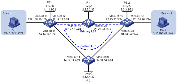
As shown in Figure 1, a company has two branches that are connected to the MPLS backbone. It requires the MPLS backbone to establish LSPs for communication between the branches, and to provide high availability services for uninterrupted business between the branches.
To meet the requirements:
· Establish LSPs by using LDP.
· Configure OSPF FRR on the MPLS backbone so LDP can establish a primary LSP and a backup LSP.
· Configure BFD for the primary LSP. When the primary LSP fails, BFD can quickly detect the failure and notify LDP of the failure, so LDP can immediately switch traffic to the backup LSP.
Software versions used
This configuration example was created and verified on S6890-CMW710-R2712.
Restrictions and guidelines
Before configuration, disable the spanning tree feature globally or map each VLAN to an MSTI.
By default, interfaces on the device are disabled (in ADM or Administratively Down state). To have an interface operate, you must use the undo shutdown command to enable that interface.
Procedures
1. Configure IP addresses for interfaces:
# On PE 1, configure IP addresses and masks for interfaces, including the loopback interface, as shown in Figure 1.
<PE1> system-view
[PE1] vlan 10
[PE1-vlan10] port ten-gigabitethernet 1/0/3
[PE1-vlan10] quit
[PE1] interface vlan-interface 10
[PE1-Vlan-interface10] ip address 192.168.10.1 24
[PE1] vlan 12
[PE1-vlan12] port ten-gigabitethernet 1/0/1
[PE1-vlan12] quit
[PE1] interface vlan-interface 12
[PE1-Vlan-interface12] ip address 12.12.12.1 24
[PE1-Vlan-interface12] quit
[PE1] vlan 14
[PE1-vlan14] port ten-gigabitethernet 1/0/2
[PE1-vlan14] quit
[PE1] interface vlan-interface 14
[PE1-Vlan-interface14] ip address 14.14.14.1 24
[PE1-Vlan-interface14] quit
[PE1] interface loopback 0
[PE1-LoopBack0] ip address 1.1.1.1 32
[PE1-LoopBack0] quit
# Configure other devices in the same way that PE 1 is configured. (Details not shown.)
2. Configure OSPF to ensure IP connectivity within the MPLS backbone, and enable OSPF FRR:
# Configure PE 1.
[PE1] ospf
[PE1-ospf-1] area 0
[PE1-ospf-1-area-0.0.0.0] network 1.1.1.1 0.0.0.0
[PE1-ospf-1-area-0.0.0.0] network 12.12.12.0 0.0.0.255
[PE1-ospf-1-area-0.0.0.0] network 14.14.14.0 0.0.0.255
[PE1-ospf-1-area-0.0.0.0] network 192.168.10.0 0.0.0.255
[PE1-ospf-1-area-0.0.0.0] quit
[PE1-ospf-1] fast-reroute lfa
[PE1-ospf-1] quit
# Configure P 1.
[P1] ospf
[P1-ospf-1] area 0
[P1-ospf-1-area-0.0.0.0] network 2.2.2.2 0.0.0.0
[P1-ospf-1-area-0.0.0.0] network 12.12.12.0 0.0.0.255
[P1-ospf-1-area-0.0.0.0] network 23.23.23.0 0.0.0.255
[P1-ospf-1-area-0.0.0.0] quit
[P1-ospf-1] quit
# Configure PE 2.
[PE2] ospf
[PE2-ospf-1] area 0
[PE2-ospf-1-area-0.0.0.0] network 3.3.3.3 0.0.0.0
[PE2-ospf-1-area-0.0.0.0] network 23.23.23.0 0.0.0.255
[PE2-ospf-1-area-0.0.0.0] network 34.34.34..0 0.0.0.255
[PE2-ospf-1-area-0.0.0.0] network 192.168.20.0 0.0.0.255
[PE2-ospf-1-area-0.0.0.0] quit
[PE2-ospf-1] fast-reroute lfa
[PE2-ospf-1] quit
# Configure P 2.
[P2] ospf
[P2-ospf-1] area 0
[P2-ospf-1-area-0.0.0.0] network 4.4.4.4 0.0.0.0
[P2-ospf-1-area-0.0.0.0] network 14.14.14.0 0.0.0.255
[P2-ospf-1-area-0.0.0.0] network 34.34.34.0 0.0.0.255
[P2-ospf-1-area-0.0.0.0] quit
[P2-ospf-1] quit
# On P 2, set the OSPF cost to 10 for VLAN-interface 14 and VLAN-interface 34. This setting ensures that the backup LSP has a larger OSPF cost than the primary LSP.
[P2] interface vlan-interface 14
[P2-Vlan-interface14] ospf cost 10
[P2-Vlan-interface14] quit
[P2] interface vlan-interface 34
[P2-Vlan-interface34] ospf cost 10
[P2-Vlan-interface34] quit
3. Configure basic MPLS and MPLS LDP:
# Configure PE 1.
[PE1] mpls lsr-id 1.1.1.1
[PE1] mpls ldp
[PE1-ldp] quit
[PE1] interface vlan-interface 12
[PE1-Vlan-interface12] mpls enable
[PE1-Vlan-interface12] mpls ldp enable
[PE1-Vlan-interface12] quit
[PE1] interface vlan-interface 14
[PE1-Vlan-interface14] mpls enable
[PE1-Vlan-interface14] mpls ldp enable
[PE1-Vlan-interface14] quit
# Configure P 1.
[P1] mpls lsr-id 2.2.2.2
[P1] mpls ldp
[P1-ldp] quit
[P1] interface vlan-interface 12
[P1-Vlan-interface12] mpls enable
[P1-Vlan-interface12] mpls ldp enable
[P1-Vlan-interface12] quit
[P1] interface vlan-interface 23
[P1-Vlan-interface23] mpls enable
[P1-Vlan-interface23] mpls ldp enable
[P1-Vlan-interface23] quit
# Configure PE 2.
[PE2] mpls lsr-id 3.3.3.3
[PE2] mpls ldp
[PE2-ldp] quit
[PE2] interface vlan-interface 23
[PE2-Vlan-interface23] mpls enable
[PE2-Vlan-interface23] mpls ldp enable
[PE2-Vlan-interface23] quit
[PE2] interface vlan-interface 34
[PE2-Vlan-interface34] mpls enable
[PE2-Vlan-interface34] mpls ldp enable
[PE2-Vlan-interface34] quit
# Configure P 2.
[P2] mpls lsr-id 4.4.4.4
[P2] mpls ldp
[P2-ldp] quit
[P2] interface vlan-interface 14
[P2-Vlan-interface14] mpls enable
[P2-Vlan-interface14] mpls ldp enable
[P2-Vlan-interface14] quit
[P2] interface vlan-interface 34
[P2-Vlan-interface34] mpls enable
[P2-Vlan-interface34] mpls ldp enable
[P2-Vlan-interface34] quit
# Verify that LDP sessions in Operational state have been established on each device. The following shows the output on PE 1.
[PE1] display mpls ldp peer
Total number of peers: 2
Peer LDP ID State Role GR MD5 KA Sent/Rcvd
2.2.2.2:0 Operational Passive Off Off 55/55
4.4.4.4:0 Operational Passive Off Off 6/6
4. Configure LSP generation policies to establish LSPs for destinations 192.168.10.0/24, 192.168.20.0/24, 1.1.1.1/32, and 3.3.3.3/32:
# On PE 1, create IP prefix list PE1, and configure LDP to use only the routes permitted by the prefix list to establish LSPs.
[PE1] ip prefix-list PE1 index 10 permit 192.168.10.0 24
[PE1] ip prefix-list PE1 index 20 permit 192.168.20.0 24
[PE1] ip prefix-list PE1 index 30 permit 1.1.1.1 32
[PE1] ip prefix-list PE1 index 40 permit 3.3.3.3 32
[PE1] mpls ldp
[PE1-ldp] lsp-trigger prefix-list PE1
[PE1-ldp] quit
# On P 1, create IP prefix list P1, and configure LDP to use only the routes permitted by the prefix list to establish LSPs.
[P1] ip prefix-list P1 index 10 permit 192.168.10.0 24
[P1] ip prefix-list P1 index 20 permit 192.168.20.0 24
[P1] ip prefix-list P1 index 30 permit 1.1.1.1 32
[P1] ip prefix-list P1 index 40 permit 3.3.3.3 32
[P1] mpls ldp
[P1-ldp] lsp-trigger prefix-list P1
[P1-ldp] quit
# On PE 2, create IP prefix list PE2, and configure LDP to use only the routes permitted by the prefix list to establish LSPs.
[PE2] ip prefix-list PE2 index 10 permit 192.168.10.0 24
[PE2] ip prefix-list PE2 index 20 permit 192.168.20.0 24
[PE2] ip prefix-list PE2 index 30 permit 1.1.1.1 32
[PE2] ip prefix-list PE2 index 40 permit 3.3.3.3 32
[PE2] mpls ldp
[PE2-ldp] lsp-trigger prefix-list PE2
[PE2-ldp] quit
# On P 2, create IP prefix list P2, and configure LDP to use only the routes permitted by the prefix list to establish LSPs.
[P2] ip prefix-list P2 index 10 permit 192.168.10.0 24
[P2] ip prefix-list P2 index 20 permit 192.168.20.0 24
[P2] ip prefix-list P2 index 30 permit 1.1.1.1 32
[P2] ip prefix-list P2 index 40 permit 3.3.3.3 32
[P2] mpls ldp
[P2-ldp] lsp-trigger prefix-list P2
[P2-ldp] quit
# Verify that LSPs to destination 192.168.20.0/24 have been established on PE 1. The primary LSP uses VLAN-interface 12 as the outgoing interface and the backup LSP uses VLAN-interface 14 as the outgoing interface.
[PE1]display mpls ldp lsp
Status Flags: * - stale, L - liberal, B - backup
Statistics:
FECs: 4 Ingress LSPs: 4 Transit LSPs: 4 Egress LSPs: 2
FEC In/Out Label Nexthop OutInterface
1.1.1.1/32 3/-
-/1151(L)
-/1279(L)
3.3.3.3/32 -/1150 12.12.12.2 Vlan12
1150/1150 12.12.12.2 Vlan12
-/1150(B) 12.12.12.2 Vlan14
1150/1150(B) 12.12.12.2 Vlan14
192.168.10.0/24 1141/-
-/1141(L)
-/1141(L)
192.168.20.0/24 -/1133 12.12.12.2 Vlan12
1133/1133 12.12.12.2 Vlan12
-/1133(B) 14.14.14.4 Vlan14
1133/1133(B) 14.14.14.4 Vlan14
5. Enable BFD for MPLS and use BFD to verify LSP connectivity:
# Configure PE 1.
[PE1] mpls bfd enable
[PE1] mpls bfd 3.3.3.3 32
# Configure PE 2.
[PE2] mpls bfd enable
[PE2] mpls bfd 1.1.1.1 32
Verifying the configuration
1. Display BFD information for LSPs on PE 1 and PE 2. The following shows the output on PE 1.
[PE1]display mpls bfd
Total number of sessions: 2, 2 up, 0 down, 0 init
FEC Type: LSP
FEC Info:
Destination: 1.1.1.1
Mask Length: 32
NHLFE ID: -
Local Discr: 1026 Remote Discr: 514
Source IP: 1.1.1.1 Destination IP: 3.3.3.3
Session State: Up Session Role: Active
Template Name: -
FEC Type: LSP
FEC Info:
Destination: 3.3.3.3
Mask Length: 32
NHLFE ID: 1028
Local Discr: 1025 Remote Discr: -
Source IP: 1.1.1.1 Destination IP: 127.0.0.1
Session State: Up Session Role: Passive
Template Name: -
2. Execute the tracert mpls ipv4 command on PE 1. The output shows that the primary LSP is in use.
|
|
NOTE: Before you use the tracert feature, enable sending ICMP time exceeded messages on intermediate devices, and enable sending ICMP destination unreachable messages on the destination device. |
<PE1>tracert mpls -a 192.168.10.1 ipv4 192.168.20.0 24
MPLS trace route FEC 192.168.20.0/24
TTL Replier Time Type Downstream
0 Ingress 12.12.12.2/[1148]
1 12.12.12.2 2 ms Transit 23.23.23.3/[1148]
2 23.23.23.3 2 ms Egress
3. Verify that the ping operation from PE 1 to PE 2 will not fail after VLAN-interface 23 on P 1 is shut down during the ping operation:
# Ping PE 2 from PE 1.
<PE1> ping -c 100000 -a 192.168.10.1 192.168.20.1
Ping 192.168.20.1 (192.168.20.1) from 192.168.10.1: 56 data bytes, press CTRL_C
to break
56 bytes from 192.168.20.1: icmp_seq=0 ttl=254 time=2.576 ms
56 bytes from 192.168.20.1: icmp_seq=1 ttl=254 time=1.996 ms
…
# Shut down VLAN-interface 23 on P 1.
[P1] interface vlan-interface 23
[P1-Vlan-interface23] shutdown
# View the ping command output. The output shows that the communication was interrupted, and then immediately resumed.
<PE1> ping -c 100000 -a 192.168.10.1 192.168.20.1
Ping 192.168.20.1 (192.168.20.1) from 192.168.10.1: 56 data bytes, press CTRL_C
to break
56 bytes from 192.168.20.1: icmp_seq=0 ttl=254 time=2.576 ms
56 bytes from 192.168.20.1: icmp_seq=1 ttl=254 time=1.996 ms
…
56 bytes from 192.168.20.1: icmp_seq=7 ttl=254 time=2.214 ms
Request time out
56 bytes from 192.168.20.1: icmp_seq=9 ttl=254 time=2.659 ms
56 bytes from 192.168.20.1: icmp_seq=10 ttl=254 time=5.049 ms
56 bytes from 192.168.20.1: icmp_seq=11 ttl=254 time=2.098 ms
56 bytes from 192.168.20.1: icmp_seq=12 ttl=254 time=2.225 ms
56 bytes from 192.168.20.1: icmp_seq=13 ttl=254 time=2.187 ms
--- Ping statistics for 192.168.20.1 ---
14 packet(s) transmitted, 13 packet(s) received, 7.1% packet loss
round-trip min/avg/max/std-dev = 1.990/2.455/5.049/0.772 ms
4. Execute the tracert mpls ipv4 command on PE 1. The output shows that the backup LSP is in use.
<PE1> tracert mpls -a 192.168.10.1 ipv4 192.168.20.0 24
MPLS trace route FEC 192.168.20.0/24
TTL Replier Time Type Downstream
0 Ingress 14.14.14.4/[1276]
1 14.14.14.4 2 ms Transit 34.34.34.3/[1148]
2 34.34.34.3 2 ms Egress
Configuration files
· PE 1:
#
ospf 1
fast-reroute lfa
area 0.0.0.0
network 1.1.1.1 0.0.0.0
network 12.12.12.0 0.0.0.255
network 14.14.14.0 0.0.0.255
network 192.168.10.0 0.0.0.255
#
mpls lsr-id 1.1.1.1
#
vlan 10
#
vlan 12
#
vlan 14
#
mpls ldp
lsp-trigger prefix-list PE1
#
mpls bfd enable
#
interface LoopBack0
ip address 1.1.1.1 255.255.255.255
#
interface Vlan-interface10
ip address 192.168.10.1 255.255.255.0
#
interface Vlan-interface12
ip address 12.12.12.1 255.255.255.0
mpls enable
mpls ldp enable
#
interface Vlan-interface14
ip address 14.14.14.1 255.255.255.0
mpls enable
mpls ldp enable
#
interface Ten-GigabitEthernet1/0/1
port link-mode bridge
port access vlan 12
#
interface Ten-GigabitEthernet1/0/2
port link-mode bridge
port access vlan 14
#
interface Ten-GigabitEthernet1/0/3
port link-mode bridge
port access vlan 10
#
ip prefix-list PE1 index 10 permit 192.168.10.0 24
ip prefix-list PE1 index 20 permit 192.168.20.0 24
ip prefix-list PE1 index 30 permit 1.1.1.1 32
ip prefix-list PE1 index 40 permit 3.3.3.3 32
#
mpls bfd 3.3.3.3 32
#
· PE 2:
#
ospf 1
fast-reroute lfa
area 0.0.0.0
network 3.3.3.3 0.0.0.0
network 23.23.23.0 0.0.0.255
network 34.34.34.0 0.0.0.255
network 192.168.20.0 0.0.0.255
#
vlan 23
#
vlan 30
#
vlan 34
#
mpls lsr-id 3.3.3.3
#
mpls ldp
lsp-trigger prefix-list PE2
#
mpls bfd enable
#
interface LoopBack0
ip address 3.3.3.3 255.255.255.255
#
interface Vlan-interface23
ip address 23.23.23.3 255.255.255.0
mpls enable
mpls ldp enable
#
interface Vlan-interface30
ip address 192.168.20.1 255.255.255.0
#
interface Vlan-interface34
ip address 34.34.34.3 255.255.255.0
mpls enable
mpls ldp enable
#
interface Ten-GigabitEthernet1/0/1
port link-mode bridge
port access vlan 34
#
interface Ten-GigabitEthernet1/0/2
port link-mode bridge
port access vlan 23
#
interface Ten-GigabitEthernet1/0/3
port link-mode bridge
port access vlan 30
#
ip prefix-list PE2 index 10 permit 192.168.10.0 24
ip prefix-list PE2 index 20 permit 192.168.20.0 24
ip prefix-list PE2 index 30 permit 1.1.1.1 32
ip prefix-list PE2 index 40 permit 3.3.3.3 32
#
mpls bfd 1.1.1.1 32
#
· P 1:
#
ospf 1
area 0.0.0.0
network 2.2.2.2 0.0.0.0
network 12.12.12.0 0.0.0.255
network 23.23.23.0 0.0.0.255
#
mpls lsr-id 2.2.2.2
#
vlan 12
#
vlan 23
#
mpls ldp
lsp-trigger prefix-list P1
#
interface LoopBack0
ip address 2.2.2.2 255.255.255.255
#
interface Vlan-interface12
ip address 12.12.12.2 255.255.255.0
mpls enable
mpls ldp enable
#
interface Vlan-interface23
ip address 23.23.23.2 255.255.255.0
mpls enable
mpls ldp enable
#
interface Ten-GigabitEthernet1/0/1
port link-mode bridge
port access vlan 12
#
interface Ten-GigabitEthernet1/0/2
port link-mode bridge
port access vlan 23
#
ip prefix-list P1 index 10 permit 192.168.10.0 24
ip prefix-list P1 index 20 permit 192.168.20.0 24
ip prefix-list P1 index 30 permit 1.1.1.1 32
ip prefix-list P1 index 40 permit 3.3.3.3 32
#
· P 2:
#
ospf 1
area 0.0.0.0
network 4.4.4.4 0.0.0.0
network 14.14.14.0 0.0.0.255
network 34.34.34.0 0.0.0.255
#
mpls lsr-id 4.4.4.4
#
vlan 14
#
vlan 34
#
mpls ldp
lsp-trigger prefix-list P2
#
interface LoopBack0
ip address 4.4.4.4 255.255.255.255
#
interface Vlan-interface14
ip address 14.14.14.4 255.255.255.0
ospf cost 10
mpls enable
mpls ldp enable
#
interface Vlan-interface34
ip address 34.34.34.4 255.255.255.0
ospf cost 10
mpls enable
mpls ldp enable
#
interface Ten-GigabitEthernet1/0/1
port link-mode bridge
port access vlan 34
#
interface Ten-GigabitEthernet1/0/2
port link-mode bridge
port access vlan 14
#
ip prefix-list P2 index 10 permit 192.168.10.0 24
ip prefix-list P2 index 20 permit 192.168.20.0 24
ip prefix-list P2 index 30 permit 1.1.1.1 32
ip prefix-list P2 index 40 permit 3.3.3.3 32
#
Example: Configuring BFD for an MPLS TE tunnel
Network configuration
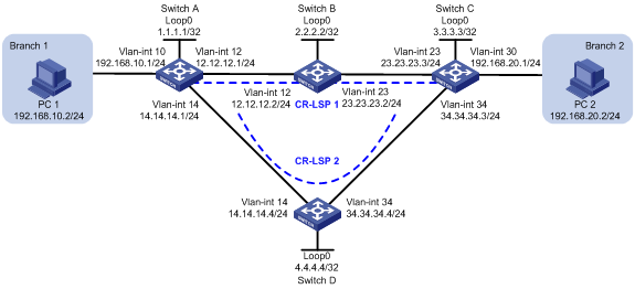
As shown in Figure 2, a company has two branches that are connected to the MPLS backbone. It requires the MPLS backbone to establish an MPLS TE tunnel for communication between the branches, and to provide high availability services for uninterrupted business between the branches.
To meet the requirements:
· Use RSVP-TE to establish an MPLS TE tunnel between Switch A and Switch C.
· Configure CRLSP backup for the MPLS TE tunnel to simultaneously establish a primary CRLSP (CR-LSP 1) and a backup CRLSP (CR-LSP 2).
· Configure BFD for the MPLS TE tunnel. When the primary CRLSP fails, BFD can quickly detect the failure and notify RSVP of the failure, so RSVP can immediately switch traffic to the backup CRLSP.
Software versions used
This configuration example was created and verified on S6890-CMW710-R2712.
Restrictions and guidelines
When you configure BFD for an MPLS TE tunnel, follow these restrictions and guidelines:
· Before configuration, disable the spanning tree feature globally or map each VLAN to an MSTI.
· OSPF TE uses Type-10 opaque LSAs to carry the TE attributes for a link. Before you configure OSPF TE, you must enable opaque LSA advertisement and reception by using the opaque-capability enable command. For more information about opaque LSA advertisement and reception, see Layer 3—IP Routing Configuration Guide.
· MPLS TE cannot reserve resources and distribute labels for an OSPF virtual link. Make sure no virtual link exists in an OSPF area before you configure MPLS TE.
· By default, interfaces on the device are disabled (in ADM or Administratively Down state). To have an interface operate, you must use the undo shutdown command to enable that interface.
Procedures
1. Configure IP addresses for interfaces:
# On Switch A, configure IP addresses and masks for interfaces, including the loopback interface, as shown in Figure 2.
<SwitchA> system-view
[SwitchA] vlan 10
[SwitchA-vlan10] port ten-gigabitethernet 1/0/3
[SwitchA-vlan10] quit
[SwitchA] interface vlan-interface 10
[SwitchA-Vlan-interface10] ip address 192.168.10.1 24
[SwitchA] vlan 12
[SwitchA-vlan12] port ten-gigabitethernet 1/0/1
[SwitchA-vlan12] quit
[SwitchA] interface vlan-interface 12
[SwitchA-Vlan-interface12] ip address 12.12.12.1 24
[SwitchA-Vlan-interface12] quit
[SwitchA] vlan 14
[SwitchA-vlan14] port ten-gigabitethernet 1/0/2
[SwitchA-vlan14] quit
[SwitchA] interface vlan-interface 14
[SwitchA-Vlan-interface14] ip address 14.14.14.1 24
[SwitchA-Vlan-interface14] quit
[SwitchA] interface loopback 0
[SwitchA-LoopBack0] ip address 1.1.1.1 32
[SwitchA-LoopBack0] quit
# Configure other devices in the same way that Switch A is configured. (Details not shown.)
2. Configure an LSR ID, and enable MPLS, MPLS TE, and RSVP-TE:
# Configure Switch A.
[SwitchA] mpls lsr-id 1.1.1.1
[SwitchA] mpls te
[SwitchA-te] quit
[SwitchA] rsvp
[SwitchA-rsvp] quit
[SwitchA] interface vlan-interface 12
[SwitchA-Vlan-interface12] mpls enable
[SwitchA-Vlan-interface12] mpls te enable
[SwitchA-Vlan-interface12] rsvp enable
[SwitchA-Vlan-interface12] quit
[SwitchA] interface vlan-interface 14
[SwitchA-Vlan-interface14] mpls enable
[SwitchA-Vlan-interface14] mpls te enable
[SwitchA-Vlan-interface14] rsvp enable
[SwitchA-Vlan-interface14] quit
# Configure Switch B, Switch C, and Switch D in the same way that Switch A is configured. (Details not shown.)
3. Configure OSPF to ensure IP connectivity within the MPLS backbone, enable opaque LSA advertisement and reception, and enable MPLS TE for OSPF area 0:
# Configure Switch A.
[SwitchA] ospf
[SwitchA-ospf-1] opaque-capability enable
[SwitchA-ospf-1] area 0
[SwitchA-ospf-1-area-0.0.0.0] mpls te enable
[SwitchA-ospf-1-area-0.0.0.0] network 1.1.1.1 0.0.0.0
[SwitchA-ospf-1-area-0.0.0.0] network 12.12.12.0 0.0.0.255
[SwitchA-ospf-1-area-0.0.0.0] network 14.14.14.0 0.0.0.255
[SwitchA-ospf-1-area-0.0.0.0] network 192.168.10.0 0.0.0.255
[SwitchA-ospf-1-area-0.0.0.0] quit
[SwitchA-ospf-1] quit
# Configure Switch B.
[SwitchB] ospf
[SwitchB-ospf-1] opaque-capability enable
[SwitchB-ospf-1] area 0
[SwitchB-ospf-1-area-0.0.0.0] mpls te enable
[SwitchB-ospf-1-area-0.0.0.0] network 2.2.2.2 0.0.0.0
[SwitchB-ospf-1-area-0.0.0.0] network 12.12.12.0 0.0.0.255
[SwitchB-ospf-1-area-0.0.0.0] network 23.23.23.0 0.0.0.255
[SwitchB-ospf-1-area-0.0.0.0] quit
[SwitchB-ospf-1] quit
# Configure Switch C.
[SwitchC] ospf
[SwitchC-ospf-1] opaque-capability enable
[SwitchC ospf-1] area 0
[SwitchC-ospf-1-area-0.0.0.0] mpls te enable
[SwitchC-ospf-1-area-0.0.0.0] network 3.3.3.3 0.0.0.0
[SwitchC ospf-1-area-0.0.0.0] network 23.23.23.0 0.0.0.255
[SwitchC ospf-1-area-0.0.0.0] network 34.34.34..0 0.0.0.255
[SwitchC ospf-1-area-0.0.0.0] network 192.168.20.0 0.0.0.255
[SwitchC ospf-1-area-0.0.0.0] quit
[SwitchC ospf-1] quit
# Configure Switch D.
[SwitchD] ospf
[SwitchD-ospf-1] opaque-capability enable
[SwitchD-ospf-1] area 0
[SwitchC-ospf-1-area-0.0.0.0] mpls te enable
[SwitchD-ospf-1-area-0.0.0.0] network 4.4.4.4 0.0.0.0
[SwitchD-ospf-1-area-0.0.0.0] network 14.14.14.0 0.0.0.255
[SwitchD-ospf-1-area-0.0.0.0] network 34.34.34.0 0.0.0.255
[SwitchD-ospf-1-area-0.0.0.0] quit
[SwitchD-ospf-1] quit
4. Configure an MPLS TE tunnel:
# On Switch A, configure MPLS TE tunnel interface Tunnel 3, and specify the tunnel destination address as the LSR ID of Switch C.
[SwitchA] interface tunnel 3 mode mpls-te
[SwitchA-Tunnel3] ip address 9.1.1.1 255.255.255.0
[SwitchA-Tunnel3] destination 3.3.3.3
# Configure MPLS TE to use RSVP-TE to establish the tunnel, and enable CRLSP hot backup for the tunnel.
[SwitchA-Tunnel3] mpls te signaling rsvp-te
[SwitchA-Tunnel3] mpls te backup hot-standby
[SwitchA-Tunnel3] quit
# Configure explicit paths for the MPLS TE tunnel.
[SwitchA] explicit-path cr-lsp1
[SwitchA-explicit-path-cr-lsp1] nexthop 12.12.12.2
[SwitchA-explicit-path-cr-lsp1] quit
[SwitchA]explicit-path cr-lsp2
[SwitchA-explicit-path-cr-lsp2] nexthop 14.14.14.4
[SwitchA-explicit-path-cr-lsp2]quit
# Set the preference to 1 for CR-LSP 1 and set the preference to 2 for CR-LSP 2.
[SwitchA] interface tunnel 3
[SwitchA-Tunnel3] mpls te path preference 1 explicit-path cr-lsp1
[SwitchA-Tunnel3] mpls te path preference 2 explicit-path cr-lsp2
[SwitchA-Tunnel3] quit
# On Switch C, configure MPLS TE tunnel interface Tunnel 3, and specify the tunnel destination address as the LSR ID of Switch A.
[SwitchC] interface tunnel 3 mode mpls-te
[SwitchC-Tunnel3] ip address 9.3.3.3 255.255.255.0
[SwitchC-Tunnel3] destination 1.1.1.1
# Configure MPLS TE to use RSVP-TE to establish the tunnel, and enable CRLSP hot backup for the tunnel.
[SwitchC-Tunnel3] mpls te signaling rsvp-te
[SwitchC-Tunnel3] mpls te backup hot-standby
[SwitchC-Tunnel3] quit
# Configure explicit paths for the MPLS TE tunnel.
[SwitchC] explicit-path cr-lsp1
[SwitchC-explicit-path-cr-lsp1] nexthop 23.23.23.2
[SwitchC-explicit-path-cr-lsp1] quit
[SwitchC]explicit-path cr-lsp2
[SwitchC-explicit-path-cr-lsp2] nexthop 34.34.34.4
[SwitchC-explicit-path-cr-lsp2]quit
# Set the preference to 1 for CR-LSP 1 and set the preference to 2 for CR-LSP 2.
[SwitchC] interface tunnel 3
[SwitchC-Tunnel3] mpls te path preference 1 explicit-path cr-lsp1
[SwitchC-Tunnel3] mpls te path preference 2 explicit-path cr-lsp2
[SwitchC-Tunnel3] quit
5. Configure static routing to direct traffic to the MPLS TE tunnel:
# Configure a static route on Switch A to direct the traffic destined for subnet 192.168.20.0/24 to MPLS TE Tunnel 3.
[SwitchA] ip route-static 192.168.20.0 24 tunnel 3 preference 1
# Configure a static route on Switch C to direct the traffic destined for subnet 192.168.10.0/24 to MPLS TE Tunnel 3.
[SwitchC] ip route-static 192.168.10.0 24 tunnel 3 preference 1
6. Enable BFD for MPLS and use BFD to verify MPLS TE tunnel connectivity:
# Configure Switch A.
[SwitchA] mpls bfd enable
[SwitchA] interface tunnel 3
[SwitchA-Tunnel3] mpls bfd
[SwitchA-Tunnel3] quit
# Configure Switch C.
[SwitchC] mpls bfd enable
[SwitchC] interface tunnel 3
[SwitchC-Tunnel3] mpls bfd
[SwitchC-Tunnel3] quit
Verifying the configuration
1. Display MPLS TE tunnel information:
# Execute the display mpls te tunnel-interface command on Switch A. The output shows that the tunnel interface Tunnel 3 is up, the primary and backup CRLSPs have been established, and hot backup is used.
<SwitchA> display mpls te tunnel-interface
Tunnel Name : Tunnel 3
Tunnel State : Up (Main CRLSP up, Backup CRLSP up)
Tunnel Attributes :
LSP ID : 37161 Tunnel ID : 3
Admin State : Normal
Ingress LSR ID : 1.1.1.1 Egress LSR ID : 3.3.3.3
Signaling : RSVP-TE Static CRLSP Name : -
Resv Style : SE
Tunnel mode : -
Reverse-LSP name : -
Reverse-LSP LSR ID : - Reverse-LSP Tunnel ID: -
Class Type : CT0 Tunnel Bandwidth : 0 kbps
Reserved Bandwidth : 0 kbps
Setup Priority : 7 Holding Priority : 7
Affinity Attr/Mask : 0/0
Explicit Path : cr-lsp1
Backup Explicit Path : -
Metric Type : TE
Record Route : Enabled Record Label : Disabled
FRR Flag : Disabled Bandwidth Protection : Disabled
Backup Bandwidth Flag: Disabled Backup Bandwidth Type: -
Backup Bandwidth : -
Bypass Tunnel : No Auto Created : No
Route Pinning : Disabled
Retry Limit : 3 Retry Interval : 2 sec
Reoptimization : Disabled Reoptimization Freq : -
Backup Type : Hot Standby Backup LSP ID : 37162
Auto Bandwidth : Disabled Auto Bandwidth Freq : -
Min Bandwidth : - Max Bandwidth : -
Collected Bandwidth : -
# Execute the display rsvp lsp verbose command on Switch A. The output shows detailed information about the primary and backup CRLSPs. The primary CRLSP uses the output interface VLAN-interface 12 and the next hop 12.12.12.2. The backup CRLSP uses the output interface VLAN-interface 14 and the next hop 14.14.14.4.
<SwitchA> display rsvp lsp destination 3.3.3.3 verbose
Tunnel name: Tunnel3
Destination: 3.3.3.3 Source: 1.1.1.1
Tunnel ID: 3 LSP ID: 37161
LSR type: Ingress Direction: Unidirectional
Setup priority: 7 Holding priority: 7
In-Label: - Out-Label: 1149
In-Interface: - Out-Interface: Vlan12
Nexthop: 12.12.12.2 Exclude-any: 0
Include-Any: 0 Include-all: 0
Mean rate (CIR): 0 kbps Mean burst size (CBS): 1000.00 bytes
Path MTU: 1500 Class type: CT0
RRO number: 6
12.12.12.1/32 Flag: 0x00 (No FRR)
12.12.12.2/32 Flag: 0x00 (No FRR)
2.2.2.2/32 Flag: 0x20 (No FRR/Node-ID)
23.23.23.2/32 Flag: 0x00 (No FRR)
23.23.23.3/32 Flag: 0x00 (No FRR)
3.3.3.3/32 Flag: 0x20 (No FRR/Node-ID)
Fast Reroute protection: None
Tunnel name: Tunnel3
Destination: 3.3.3.3 Source: 1.1.1.1
Tunnel ID: 3 LSP ID: 37162
LSR type: Ingress Direction: Unidirectional
Setup priority: 7 Holding priority: 7
In-Label: - Out-Label: 1149
In-Interface: - Out-Interface: Vlan14
Nexthop: 14.14.14.4 Exclude-any: 0
Include-Any: 0 Include-all: 0
Mean rate (CIR): 0 kbps Mean burst size (CBS): 1000.00 bytes
Path MTU: 1500 Class type: CT0
RRO number: 6
14.14.14.1/32 Flag: 0x00 (No FRR)
14.14.14.4/32 Flag: 0x00 (No FRR)
4.4.4.4/32 Flag: 0x20 (No FRR/Node-ID)
34.34.34.4/32 Flag: 0x00 (No FRR)
34.34.34.3/32 Flag: 0x00 (No FRR)
3.3.3.3/32 Flag: 0x20 (No FRR/Node-ID)
Fast Reroute protection: None
2. Display BFD information for the MPLS TE tunnel on Switch A. The output shows that BFD sessions have been established for the primary and backup CRLSPs and the state of the session is up.
<SwitchA> display mpls bfd te tunnel 3
Total number of sessions: 2, 2 up, 0 down, 0 init
FEC Type: TE Tunnel
FEC Info:
Send Addr: 1.1.1.1
End Addr: 3.3.3.3
Tunnel ID: 3
LSP ID : 37161
NHLFE ID: 1029
Local Discr: 34 Remote Discr: 33
Source IP: 1.1.1.1 Destination IP: 127.0.0.1
Session State: Up Session Role: Passive
Template Name: -
FEC Type: TE Tunnel
FEC Info:
Send Addr: 1.1.1.1
End Addr: 3.3.3.3
Tunnel ID: 3
LSP ID : 37162
NHLFE ID: 1031
Local Discr: 33 Remote Discr: 36
Source IP: 1.1.1.1 Destination IP: 127.0.0.4
Session State: Up Session Role: Passive
Template Name: -
3. Shut down VLAN-interface 23 on Switch B, and display MPLS TE tunnel information and BFD information:
# Shut down VLAN-interface 23 on Switch B.
[SwitchB] interface vlan-interface 23
[SwitchB-Vlan-interface23] shutdown
# Execute the display mpls te tunnel-interface command on Switch A. The output shows that the primary CRLSP is down and the backup CRLSP is up.
<SwitchA> display mpls te tunnel-interface
Tunnel Name : Tunnel 3
Tunnel State : Up (Main CRLSP down, Backup CRLSP up)
Tunnel Attributes :
LSP ID : 0 Tunnel ID : 3
Admin State : Normal
Ingress LSR ID : - Egress LSR ID : 3.3.3.3
Signaling : RSVP-TE Static CRLSP Name : -
Resv Style : SE
Tunnel mode : -
Reverse-LSP name : -
Reverse-LSP LSR ID : - Reverse-LSP Tunnel ID: -
Class Type : CT0 Tunnel Bandwidth : 0 kbps
Reserved Bandwidth : 0 kbps
Setup Priority : 7 Holding Priority : 7
Affinity Attr/Mask : 0/0
Explicit Path : -
Backup Explicit Path : -
Metric Type : TE
Record Route : Enabled Record Label : Disabled
FRR Flag : Disabled Bandwidth Protection : Disabled
Backup Bandwidth Flag: Disabled Backup Bandwidth Type: -
Backup Bandwidth : -
Bypass Tunnel : No Auto Created : No
Route Pinning : Disabled
Retry Limit : 3 Retry Interval : 2 sec
Reoptimization : Disabled Reoptimization Freq : -
Backup Type : Hot Standby Backup LSP ID : 37162
Auto Bandwidth : Disabled Auto Bandwidth Freq : -
Min Bandwidth : - Max Bandwidth : -
Collected Bandwidth : -
# Display BFD information for CR-LSP 2 on Switch A.
<SwitchA> display mpls bfd te tunnel 3
Total number of sessions: 1, 1 up, 0 down, 0 init
FEC Type: TE Tunnel
FEC Info:
Send Addr: 1.1.1.1
End Addr: 3.3.3.3
Tunnel ID: 3
LSP ID : 37162
NHLFE ID: 1031
Local Discr: 33 Remote Discr: 36
Source IP: 1.1.1.1 Destination IP: 127.0.0.4
Session State: Up Session Role: Passive
Template Name: -
4. Bring up VLAN-interface 23 on Switch B and display MPLS TE tunnel information:
# Bring up VLAN-interface 23 on Switch B.
[SwitchB] interface vlan-interface 23
[SwitchB-Vlan-interface23] undo shutdown
# Execute the display mpls te tunnel-interface command on Switch A. The output shows that the primary CRLSP becomes available again.
<SwitchA> display mpls te tunnel-interface
Tunnel Name : Tunnel 3
Tunnel State : Up (Main CRLSP up, Backup CRLSP up)
Tunnel Attributes :
LSP ID : 37177 Tunnel ID : 3
Admin State : Normal
Ingress LSR ID : 1.1.1.1 Egress LSR ID : 3.3.3.3
Signaling : RSVP-TE Static CRLSP Name : -
Resv Style : SE
Tunnel mode : -
Reverse-LSP name : -
Reverse-LSP LSR ID : - Reverse-LSP Tunnel ID: -
Class Type : CT0 Tunnel Bandwidth : 0 kbps
Reserved Bandwidth : 0 kbps
Setup Priority : 7 Holding Priority : 7
Affinity Attr/Mask : 0/0
Explicit Path : cr-lsp1
Backup Explicit Path : -
Metric Type : TE
Record Route : Enabled Record Label : Disabled
FRR Flag : Disabled Bandwidth Protection : Disabled
Backup Bandwidth Flag: Disabled Backup Bandwidth Type: -
Backup Bandwidth : -
Bypass Tunnel : No Auto Created : No
Route Pinning : Disabled
Retry Limit : 3 Retry Interval : 2 sec
Reoptimization : Disabled Reoptimization Freq : -
Backup Type : Hot Standby Backup LSP ID : 37178
Auto Bandwidth : Disabled Auto Bandwidth Freq : -
Min Bandwidth : - Max Bandwidth : -
Collected Bandwidth : -
Configuration files
· Switch A:
#
ospf 1
area 0.0.0.0
network 1.1.1.1 0.0.0.0
network 12.12.12.0 0.0.0.255
network 14.14.14.0 0.0.0.255
network 192.168.10.0 0.0.0.255
mpls te enable
#
mpls lsr-id 1.1.1.1
#
vlan 10
#
vlan 12
#
vlan 14
#
mpls te
#
explicit-path cr-lsp1
nexthop index 1 12.12.12.2 include strict
#
explicit-path cr-lsp2
nexthop index 1 14.14.14.4 include strict
#
rsvp
#
mpls bfd enable
#
interface LoopBack0
ip address 1.1.1.1 255.255.255.255
#
interface Vlan-interface10
ip address 192.168.10.1 255.255.255.0
#
interface Vlan-interface12
ip address 12.12.12.1 255.255.255.0
mpls enable
mpls te enable
rsvp enable
#
interface Vlan-interface14
ip address 14.14.14.1 255.255.255.0
mpls enable
mpls te enable
rsvp enable
#
interface Ten-GigabitEthernet1/0/1
port link-mode bridge
port access vlan 12
#
interface Ten-GigabitEthernet1/0/2
port link-mode bridge
port access vlan 14
#
interface Ten-GigabitEthernet1/0/3
port link-mode bridge
port access vlan 10
#
interface Tunnel3 mode mpls-te
ip address 9.1.1.1 255.255.255.0
mpls te path preference 1 explicit-path cr-lsp1
mpls te path preference 2 explicit-path cr-lsp2
mpls te backup hot-standby
mpls bfd
destination 3.3.3.3
#
ip route-static 192.168.20.0 24 Tunnel3 preference 1
#
· Switch B:
#
ospf 1
area 0.0.0.0
network 2.2.2.2 0.0.0.0
network 12.12.12.0 0.0.0.255
network 23.23.23.0 0.0.0.255
mpls te enable
#
mpls lsr-id 2.2.2.2
#
vlan 12
#
vlan 23
#
mpls te
#
rsvp
#
interface LoopBack0
ip address 2.2.2.2 255.255.255.255
#
interface Vlan-interface12
ip address 12.12.12.2 255.255.255.0
mpls enable
mpls te enable
rsvp enable
#
interface Vlan-interface23
ip address 23.23.23.2 255.255.255.0
mpls enable
mpls te enable
rsvp enable
#
interface Ten-GigabitEthernet1/0/1
port link-mode bridge
port access vlan 12
#
interface Ten-GigabitEthernet1/0/2
port link-mode bridge
port access vlan 23
#
· Switch C:
#
ospf 1
area 0.0.0.0
network 3.3.3.3 0.0.0.0
network 23.23.23.0 0.0.0.255
network 34.34.34.0 0.0.0.255
network 192.168.20.0 0.0.0.255
mpls te enable
#
mpls lsr-id 3.3.3.3
#
vlan 23
#
vlan 30
#
vlan 34
#
mpls te
#
explicit-path cr-lsp1
nexthop index 1 23.23.23.2 include strict
#
explicit-path cr-lsp2
nexthop index 1 34.34.34.4 include strict
#
rsvp
#
mpls bfd enable
#
interface LoopBack0
ip address 3.3.3.3 255.255.255.255
#
interface Vlan-interface23
ip address 23.23.23.3 255.255.255.0
mpls enable
mpls te enable
rsvp enable
#
interface Vlan-interface30
ip address 192.168.20.1 255.255.255.0
#
interface Vlan-interface34
ip address 34.34.34.3 255.255.255.0
mpls enable
mpls te enable
rsvp enable
#
interface Ten-GigabitEthernet1/0/1
port link-mode bridge
port access vlan 34
#
interface Ten-GigabitEthernet1/0/2
port link-mode bridge
port access vlan 23
#
interface Ten-GigabitEthernet1/0/3
port link-mode bridge
port access vlan 30
#
interface Tunnel3 mode mpls-te
ip address 9.3.3.3 255.255.255.0
mpls te path preference 1 explicit-path cr-lsp1
mpls te path preference 2 explicit-path cr-lsp2
mpls te backup hot-standby
mpls bfd
destination 1.1.1.1
#
ip route-static 192.168.10.0 24 Tunnel3 preference 1
#
· Switch D:
#
ospf 1
area 0.0.0.0
network 4.4.4.4 0.0.0.0
network 14.14.14.0 0.0.0.255
network 34.34.34.0 0.0.0.255
mpls te enable
#
mpls lsr-id 4.4.4.4
#
vlan 14
#
vlan 34
#
mpls te
#
rsvp
#
interface LoopBack0
ip address 4.4.4.4 255.255.255.255
#
interface Vlan-interface14
ip address 14.14.14.4 255.255.255.0
mpls enable
mpls te enable
rsvp enable
#
interface Vlan-interface34
ip address 34.34.34.4 255.255.255.0
mpls enable
mpls te enable
rsvp enable
#
interface Ten-GigabitEthernet1/0/1
port link-mode bridge
port access vlan 34
#
interface Ten-GigabitEthernet1/0/2
port link-mode bridge
port access vlan 14
#
Related documentation
· H3C S6890 Switch Series MPLS Command Reference (R27xx)
· H3C S6890 Switch Series MPLS Configuration Guide (R27xx)