- Table of Contents
-
- H3C S6890 Switch Series Configuration Examples-Release 27xx-6W100
- 01-Login Management Configuration Examples
- 02-RBAC Configuration Examples
- 03-Software Upgrade Examples
- 04-ISSU Configuration Examples
- 05-Software Patching Examples
- 06-Ethernet Link Aggregation Configuration Examples
- 07-Port Isolation Configuration Examples
- 08-Spanning Tree Configuration Examples
- 09-VLAN Configuration Examples
- 10-VLAN Tagging Configuration Examples
- 11-DHCP Snooping Configuration Examples
- 12-Cross-Subnet Dynamic IP Address Allocation Configuration Examples
- 13-GRE Tunnel Configuration Examples
- 14-GRE with OSPF Configuration Examples
- 15-OSPF Configuration Examples
- 16-IS-IS Configuration Examples
- 17-BGP Configuration Examples
- 18-Policy-Based Routing Configuration Examples
- 19-OSPFv3 Configuration Examples
- 20-IPv6 IS-IS Configuration Examples
- 21-Routing Policy Configuration Examples
- 22-IGMP Snooping Configuration Examples
- 23-IGMP Configuration Examples
- 24-Multicast VPN Configuration Examples
- 25-Basic MPLS Configuration Examples
- 26-MPLS L3VPN Configuration Examples
- 27-ACL Configuration Examples
- 28-Control Plane-Based QoS Policy Configuration Examples
- 29-Traffic Policing Configuration Examples
- 30-GTS and Rate Limiting Configuration Examples
- 31-Priority Mapping and Queue Scheduling Configuration Examples
- 32-Traffic Filtering Configuration Examples
- 33-AAA Configuration Examples
- 34-SSH Configuration Examples
- 35-IP Source Guard Configuration Examples
- 36-Ethernet OAM Configuration Examples
- 37-CFD Configuration Examples
- 38-DLDP Configuration Examples
- 39-VRRP Configuration Examples
- 40-BFD Configuration Examples
- 41-NTP Configuration Examples
- 42-SNMP Configuration Examples
- 43-NQA Configuration Examples
- 44-Mirroring Configuration Examples
- 45-sFlow Configuration Examples
- 46-FCoE Configuration Examples
- 47-OpenFlow Configuration Examples
- 48-MAC Address Table Configuration Examples
- 49-Static Multicast MAC Address Entry Configuration Examples
- 50-IP Unnumbered Configuration Examples
- 51-MVRP Configuration Examples
- 52-MCE Configuration Examples
- 53-Congestion Avoidance and Queue Scheduling Configuration Examples
- 54-Attack Protection Configuration Examples
- 55-Smart Link Configuration Examples
- 56-RRPP Configuration Examples
- 57-BGP Route Selection Configuration Examples
- 58-IS-IS Route Summarization Configuration Examples
- 59-IRF Configuration Examples
- 60-MPLS OAM Configuration Examples
- 61-MPLS TE Configuration Examples
- 62-VXLAN Configuration Examples
- 63-DRNI Configuration Examples
- 64-DRNI and EVPN Configuration Examples
- 65-VCF Fabric Configuration Examples
- Related Documents
-
| Title | Size | Download |
|---|---|---|
| 64-DRNI and EVPN Configuration Examples | 304.16 KB |
|
|
|
H3C S6890 Switch Series |
|
DRNI and EVPN Configuration Examples |
|
|
Document version: 6W100-20190628
Copyright © 2019 New H3C Technologies Co., Ltd. All rights reserved.
No part of this manual may be reproduced or transmitted in any form or by any means without prior written consent of New H3C Technologies Co., Ltd.
Except for the trademarks of New H3C Technologies Co., Ltd., any trademarks that may be mentioned in this document are the property of their respective owners.
The information in this document is subject to change without notice.
Contents
General restrictions and guidelines
Example: Configuring DRNI using an Ethernet aggregate link as the IPL on EVPN VTEPs
Configuring routed (Layer 3) interfaces
Configuring BGP to advertise BGP EVPN routes
Mapping Ethernet service instances to VSIs
Verifying the configuration on a DR member device
Verifying the network connectivity of the VMs
Example: Configuring DRNI using a VXLAN tunnel as the IPL on EVPN VTEPs
Configuring Layer 3 interfaces
Configuring BGP to advertise BGP EVPN routes
Mapping Ethernet service instances to VSIs
Verifying the configuration on a DR member device
Verifying the network connectivity of the VMs
Example: Configuring DRNI using an Ethernet aggregate link as the IPL on EVPN gateways
Configuring Layer 3 interfaces
Configuring distributed EVPN gateways
Configuring BGP to advertise BGP EVPN routes
Mapping Ethernet service instances to VSIs
Verifying the configuration on a DR member device
Verifying the network connectivity of the VMs
Example: Configuring DRNI using a VXLAN tunnel as the IPL on EVPN gateways
Configuring Layer 3 interfaces
Configuring distributed EVPN gateways
Configuring BGP to advertise BGP EVPN routes
Mapping Ethernet service instances to VSIs
Verifying the configuration on a DR member device
Verifying the network connectivity of the VMs
Introduction
This document provides configuration examples for using Distributed Resilient Network Interconnect (DRNI) on an Ethernet Virtual Private Network (EVPN) network.
DRNI virtualizes two physical devices into one system through multichassis link aggregation. You can use DRNI to virtualize two VTEPs or EVPN gateways into one distributed-relay (DR) system to avoid single points of failure.
Prerequisites
The configuration examples were created and verified in a lab environment, and all the devices were started with the factory default configuration. When you are working on a live network, make sure you understand the potential impact of every command on your network.
The following information is provided based on the assumption that you have basic knowledge of DRNI and EVPN.
General restrictions and guidelines
Before you can configure EVPN, you must perform the following tasks:
1. Set the system operating mode to standard by using the system-working-mode standard command.
2. Save the configuration.
3. Reboot the device.
If the device is a VTEP, enable Layer 2 or Layer 3 forwarding for VXLANs. If the device is an EVPN gateway, enable Layer 3 forwarding for VXLANs.
Example: Configuring DRNI using an Ethernet aggregate link as the IPL on EVPN VTEPs
Network configuration
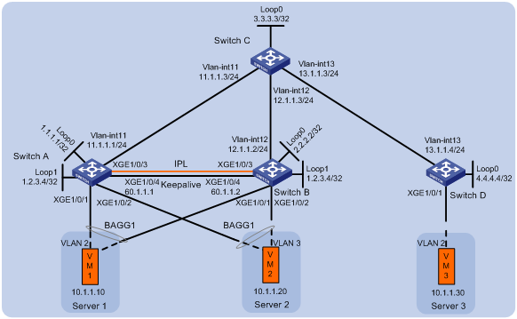
As shown in Figure 1, perform the following tasks to make sure the VMs can communicate with one another:
· Configure VXLAN 10 on Switch A, Switch B, and Switch D.
· Configure DRNI on Switch A and Switch B to virtualize them into one VTEP. Configure an Ethernet aggregate link as the IPL between the switches.
· Configure Switch C as a route reflector (RR).
Analysis
To conserve resources, configure Switch C to reflect routes for Switch A, Switch B, and Switch D.
Software versions used
This configuration example was created and verified on S6890 CMW710-R2712.
Restrictions and guidelines
In a DR system, DR member devices must have the same EVPN configuration.
Make sure the outer VLAN IDs configured on Ethernet service instances of different VSIs do not overlap. The Ethernet service interfaces that match the same outer VLAN ID on different ports must be mapped to the same VSI.
For EVPN to run correctly on a DR system, you must execute the undo mac-address static source-check enable command on IPPs and IRF physical interfaces of the DR member devices.
As a best practice, use the IP address of a loopback interface as the virtual VTEP address.
By default, interfaces on S6890 switches are disabled (in ADM or Administratively Down state). To have an interface operate, you must use the undo shutdown command to enable that interface.
Procedures
Configuring routed (Layer 3) interfaces
# Configure the Layer 3 interfaces on Switch A.
<SwitchA> system-view
[SwitchA] interface loopback 0
[SwitchA-Loopback0] ip address 1.1.1.1 32
[SwitchA-Loopback0] quit
[SwitchA] interface loopback 1
[SwitchA-Loopback1] ip address 1.2.3.4 32
[SwitchA-Loopback1] quit
[SwitchA] vlan 11
[SwitchA-vlan11] port ten-gigabitethernet 1/0/5
[SwitchA-vlan11] quit
[SwitchA] interface vlan-interface 11
[SwitchA-Vlan-interface11] ip address 11.1.1.1 24
[SwitchA-Vlan-interface11] quit
[SwitchA] interface ten-gigabitethernet 1/0/4
[SwitchA-Ten-GigabitEthernet1/0/4] port link-mode route
[SwitchA-Ten-GigabitEthernet1/0/4] ip address 60.1.1.1 24
[SwitchA-Ten-GigabitEthernet1/0/4] quit
# Configure the Layer 3 interfaces on other switches. (Details not shown.)
Configuring OSPF
Configuring Switch A
# Configure OSPF to advertise the networks attached to the Layer 3 interfaces.
[SwitchA] ospf 1 router-id 1.1.1.1
[SwitchA-ospf-1] area 0
[SwitchA-ospf-1-area-0.0.0.0] network 1.1.1.1 0.0.0.0
[SwitchA-ospf-1-area-0.0.0.0] network 1.2.3.4 0.0.0.0
[SwitchA-ospf-1-area-0.0.0.0] network 11.1.1.0 0.0.0.255
[SwitchA-ospf-1-area-0.0.0.0] quit
[SwitchA-ospf-1] quit
Configuring Switch B
# Configure OSPF to advertise the networks attached to the Layer 3 interfaces.
<SwitchB> system-view
[SwitchB] ospf 1 router-id 2.2.2.2
[SwitchB-ospf-1] area 0
[SwitchB-ospf-1-area-0.0.0.0] network 2.2.2.2 0.0.0.0
[SwitchB-ospf-1-area-0.0.0.0] network 1.2.3.4 0.0.0.0
[SwitchB-ospf-1-area-0.0.0.0] network 12.1.1.0 0.0.0.255
[SwitchB-ospf-1-area-0.0.0.0] quit
[SwitchB-ospf-1] quit
Configuring Switch C
# Configure OSPF to advertise the networks attached to the Layer 3 interfaces.
<SwitchC> system-view
[SwitchC] ospf 1 router-id 3.3.3.3
[SwitchC-ospf-1] area 0
[SwitchC-ospf-1-area-0.0.0.0] network 3.3.3.3 0.0.0.0
[SwitchC-ospf-1-area-0.0.0.0] network 11.1.1.0 0.0.0.255
[SwitchC-ospf-1-area-0.0.0.0] network 12.1.1.0 0.0.0.255
[SwitchC-ospf-1-area-0.0.0.0] network 13.1.1.0 0.0.0.255
[SwitchC-ospf-1-area-0.0.0.0] quit
[SwitchC-ospf-1] quit
Configuring Switch D
# Configure OSPF to advertise the networks attached to the Layer 3 interfaces.
<SwitchD> system-view
[SwitchD] ospf 1 router-id 4.4.4.4
[SwitchD-ospf-1] area 0
[SwitchD-ospf-1-area-0.0.0.0] network 4.4.4.4 0.0.0.0
[SwitchD-ospf-1-area-0.0.0.0] network 13.1.1.0 0.0.0.255
[SwitchD-ospf-1-area-0.0.0.0] quit
[SwitchD-ospf-1] quit
Configuring EVPN
Configuring Switch A
# Enable L2VPN.
[SwitchA] l2vpn enable
# Disable remote MAC address learning and remote ARP learning.
[SwitchA] vxlan tunnel mac-learning disable
[SwitchA] vxlan tunnel arp-learning disable
# Enable Layer 2 forwarding for VXLANs.
[SwitchA] undo vxlan ip-forwarding
# Create an EVPN instance on VSI vpna.
[SwitchA] vsi vpna
[SwitchA-vsi-vpna] arp suppression enable
[SwitchA-vsi-vpna] evpn encapsulation vxlan
# Configure the switch to automatically generate an RD and a route target for the EVPN instance.
[SwitchA-vsi-vpna-evpn-vxlan] route-distinguisher auto
[SwitchA-vsi-vpna-evpn-vxlan] vpn-target auto
[SwitchA-vsi-vpna-evpn-vxlan] quit
# Create VXLAN 10.
[SwitchA-vsi-vpna] vxlan 10
[SwitchA-vsi-vpna-vxlan-10] quit
[SwitchA-vsi-vpna] quit
Configuring Switch B
# Enable L2VPN.
[SwitchB] l2vpn enable
# Disable remote MAC address learning and remote ARP learning.
[SwitchB] vxlan tunnel mac-learning disable
[SwitchB] vxlan tunnel arp-learning disable
# Enable Layer 2 forwarding for VXLANs.
[SwitchB] undo vxlan ip-forwarding
# Create an EVPN instance on VSI vpna.
[SwitchB] vsi vpna
[SwitchB-vsi-vpna] arp suppression enable
[SwitchB-vsi-vpna] evpn encapsulation vxlan
# Configure the switch to automatically generate an RD and a route target for the EVPN instance.
[SwitchB-vsi-vpna-evpn-vxlan] route-distinguisher auto
[SwitchB-vsi-vpna-evpn-vxlan] vpn-target auto
[SwitchB-vsi-vpna-evpn-vxlan] quit
# Create VXLAN 10.
[SwitchB-vsi-vpna] vxlan 10
[SwitchB-vsi-vpna-vxlan-10] quit
[SwitchB-vsi-vpna] quit
Configuring Switch D
# Enable L2VPN.
[SwitchD] l2vpn enable
# Disable remote MAC address learning and remote ARP learning.
[SwitchD] vxlan tunnel mac-learning disable
[SwitchD] vxlan tunnel arp-learning disable
# Enable Layer 2 forwarding for VXLANs.
[SwitchD] undo vxlan ip-forwarding
# Create an EVPN instance on VSI vpna.
[SwitchD] vsi vpna
[SwitchD-vsi-vpna] arp suppression enable
[SwitchD-vsi-vpna] evpn encapsulation vxlan
# Configure the switch to automatically generate an RD and a route target for the EVPN instance.
[SwitchD-vsi-vpna-evpn-vxlan] route-distinguisher auto
[SwitchD-vsi-vpna-evpn-vxlan] vpn-target auto
[SwitchD-vsi-vpna-evpn-vxlan] quit
# Create VXLAN 10.
[SwitchD-vsi-vpna] vxlan 10
[SwitchD-vsi-vpna-vxlan-10] quit
[SwitchD-vsi-vpna] quit
Configuring DRNI
Configuring Switch A
# Specify the virtual VTEP address as 1.2.3.4.
[SwitchA] evpn drni group 1.2.3.4
# Configure DR system parameters.
[SwitchA] drni system-mac 0001-0001-0001
[SwitchA] drni system-number 1
[SwitchA] drni system-priority 10
[SwitchA] drni restore-delay 180
[SwitchA] drni keepalive ip destination 60.1.1.2 source 60.1.1.1
# Create Layer 2 dynamic aggregate interface Bridge-Aggregation 3.
[SwitchA] interface bridge-aggregation 3
[SwitchA-Bridge-Aggregation3] link-aggregation mode dynamic
[SwitchA-Bridge-Aggregation3] quit
# Assign Ten-GigabitEthernet 1/0/3 to aggregation group 3.
[SwitchA] interface ten-gigabitethernet 1/0/3
[SwitchA-Ten-GigabitEthernet1/0/3] port link-aggregation group 3
[SwitchA-Ten-GigabitEthernet1/0/3] quit
# Specify Bridge-Aggregation 3 as the IPP.
[SwitchA] interface bridge-aggregation 3
[SwitchA-Bridge-Aggregation3] port drni intra-portal-port 1
[SwitchA-Bridge-Aggregation3] undo mac-address static source-check enable
[SwitchA-Bridge-Aggregation3] quit
# Disable the static source check feature on Ten-GigabitEthernet 1/0/5.
[SwitchA] interface ten-gigabitethernet 1/0/5
[SwitchA-Ten-GigabitEthernet1/0/5] undo mac-address static source-check enable
[SwitchA-Ten-GigabitEthernet1/0/5] quit
# Create Layer 2 dynamic aggregate interface Bridge-Aggregation 4.
[SwitchA] interface bridge-aggregation 4
[SwitchA-Bridge-Aggregation4] link-aggregation mode dynamic
[SwitchA-Bridge-Aggregation4] quit
# Assign Ten-GigabitEthernet 1/0/1 to aggregation group 4.
[SwitchA] interface ten-gigabitethernet 1/0/1
[SwitchA-Ten-GigabitEthernet1/0/1] port link-aggregation group 4
[SwitchA-Ten-GigabitEthernet1/0/1] quit
# Assign Bridge-Aggregation 4 to DR group 4.
[SwitchA] interface bridge-aggregation 4
[SwitchA-Bridge-Aggregation4] port drni group 4
[SwitchA-Bridge-Aggregation4] quit
# Create Layer 2 dynamic aggregate interface Bridge-Aggregation 5.
[SwitchA] interface bridge-aggregation 5
[SwitchA-Bridge-Aggregation5] link-aggregation mode dynamic
[SwitchA-Bridge-Aggregation5] quit
# Assign Ten-GigabitEthernet 1/0/2 to aggregation group 5.
[SwitchA] interface ten-gigabitethernet 1/0/2
[SwitchA-Ten-GigabitEthernet1/0/2] port link-aggregation group 5
[SwitchA-Ten-GigabitEthernet1/0/2] quit
# Assign Bridge-Aggregation 5 to DR group 5.
[SwitchA] interface bridge-aggregation 5
[SwitchA-Bridge-Aggregation5] port drni group 5
[SwitchA-Bridge-Aggregation5] quit
# Exclude all interfaces used by EVPN from the shutdown action by DRNI MAD.
[SwitchA] mad exclude interface loopback 0
[SwitchA] mad exclude interface ten-gigabitethernet 1/0/4
[SwitchA] mad exclude interface ten-gigabitethernet 1/0/5
[SwitchA] mad exclude interface vlan-interface 11
Configuring Switch B
# Specify the virtual VTEP address as 1.2.3.4.
[SwitchB] evpn drni group 1.2.3.4
# Configure DR system parameters.
[SwitchB] drni system-mac 0001-0001-0001
[SwitchB] drni system-number 2
[SwitchB] drni system-priority 10
[SwitchB] drni restore-delay 180
[SwitchB] drni keepalive ip destination 60.1.1.1 source 60.1.1.2
# Create Layer 2 dynamic aggregate interface Bridge-Aggregation 3.
[SwitchB] interface bridge-aggregation 3
[SwitchB-Bridge-Aggregation3] link-aggregation mode dynamic
[SwitchB-Bridge-Aggregation3] quit
# Assign Ten-GigabitEthernet 1/0/3 to aggregation group 3.
[SwitchB] interface ten-gigabitethernet 1/0/3
[SwitchB-Ten-GigabitEthernet1/0/3] port link-aggregation group 3
[SwitchB-Ten-GigabitEthernet1/0/3] quit
# Specify Bridge-Aggregation 3 as the IPP.
[SwitchB] interface bridge-aggregation 3
[SwitchB-Bridge-Aggregation3] port drni intra-portal-port 1
[SwitchB-Bridge-Aggregation3] undo mac-address static source-check enable
[SwitchB-Bridge-Aggregation3] quit
# Disable the static source check feature on Ten-GigabitEthernet 1/0/5.
[SwitchB] interface ten-gigabitethernet 1/0/5
[SwitchB-Ten-GigabitEthernet1/0/5] undo mac-address static source-check enable
[SwitchB-Ten-GigabitEthernet1/0/5] quit
# Create Layer 2 dynamic aggregate interface Bridge-Aggregation 4.
[SwitchB] interface bridge-aggregation 4
[SwitchB-Bridge-Aggregation4] link-aggregation mode dynamic
[SwitchB-Bridge-Aggregation4] quit
# Assign Ten-GigabitEthernet 1/0/1 to aggregation group 4.
[SwitchB] interface ten-gigabitethernet 1/0/1
[SwitchB-Ten-GigabitEthernet1/0/1] port link-aggregation group 4
[SwitchB-Ten-GigabitEthernet1/0/1] quit
# Assign Bridge-Aggregation 4 to DR group 4.
[SwitchB] interface bridge-aggregation 4
[SwitchB-Bridge-Aggregation4] port drni group 4
[SwitchB-Bridge-Aggregation4] quit
# Create Layer 2 dynamic aggregate interface Bridge-Aggregation 5.
[SwitchB] interface bridge-aggregation 5
[SwitchB-Bridge-Aggregation5] link-aggregation mode dynamic
[SwitchB-Bridge-Aggregation5] quit
# Assign Ten-GigabitEthernet 1/0/2 to aggregation group 5.
[SwitchB] interface ten-gigabitethernet 1/0/2
[SwitchB-Ten-GigabitEthernet1/0/2] port link-aggregation group 5
[SwitchB-Ten-GigabitEthernet1/0/2] quit
# Assign Bridge-Aggregation 5 to DR group 5.
[SwitchB] interface bridge-aggregation 5
[SwitchB-Bridge-Aggregation5] port drni group 5
[SwitchB-Bridge-Aggregation5] quit
# Exclude all interfaces used by EVPN from the shutdown action by DRNI MAD.
[SwitchB] mad exclude interface loopback 0
[SwitchB] mad exclude interface ten-gigabitethernet 1/0/4
[SwitchB] mad exclude interface ten-gigabitethernet 1/0/5
[SwitchB] mad exclude interface vlan-interface 12
Configuring BGP to advertise BGP EVPN routes
Configuring Switch A
# Configure BGP to advertise BGP EVPN routes.
[SwitchA] bgp 200
[SwitchA-bgp-default] peer 3.3.3.3 as-number 200
[SwitchA-bgp-default] peer 3.3.3.3 connect-interface loopback 0
[SwitchA-bgp-default] address-family l2vpn evpn
[SwitchA-bgp-default-evpn] peer 3.3.3.3 enable
[SwitchA-bgp-default-evpn] quit
[SwitchA-bgp-default] quit
Configuring Switch B
# Configure BGP to advertise BGP EVPN routes.
[SwitchB] bgp 200
[SwitchB-bgp-default] peer 3.3.3.3 as-number 200
[SwitchB-bgp-default] peer 3.3.3.3 connect-interface loopback 0
[SwitchB-bgp-default] address-family l2vpn evpn
[SwitchB-bgp-default-evpn] peer 3.3.3.3 enable
[SwitchB-bgp-default-evpn] quit
[SwitchB-bgp-default] quit
Configuring Switch C
# Configure BGP to advertise BGP EVPN routes and configure the switch as an RR.
[SwitchC] bgp 200
[SwitchC-bgp-default] group evpn
[SwitchC-bgp-default] peer 1.1.1.1 group evpn
[SwitchC-bgp-default] peer 2.2.2.2 group evpn
[SwitchC-bgp-default] peer 4.4.4.4 group evpn
[SwitchC-bgp-default] peer evpn as-number 200
[SwitchC-bgp-default] peer evpn connect-interface loopback 0
[SwitchC-bgp-default] address-family l2vpn evpn
[SwitchC-bgp-default-evpn] peer evpn enable
[SwitchC-bgp-default-evpn] undo policy vpn-target
[SwitchC-bgp-default-evpn] peer evpn reflect-client
[SwitchC-bgp-default-evpn] quit
[SwitchC-bgp-default] quit
Configuring Switch D
# Configure BGP to advertise BGP EVPN routes.
[SwitchD] bgp 200
[SwitchD-bgp-default] peer 3.3.3.3 as-number 200
[SwitchD-bgp-default] peer 3.3.3.3 connect-interface loopback 0
[SwitchD-bgp-default] address-family l2vpn evpn
[SwitchD-bgp-default-evpn] peer 3.3.3.3 enable
[SwitchD-bgp-default-evpn] quit
[SwitchD-bgp-default] quit
Mapping Ethernet service instances to VSIs
Configuring Switch A
# On Bridge-Aggregation 4, create Ethernet service instance 1000 to match VLAN 2.
[SwitchA] interface bridge-aggregation 4
[SwitchA-Bridge-Aggregation4] service-instance 1000
[SwitchA-Bridge-Aggregation4-srv1000] encapsulation s-vid 2
# Map Ethernet service instance 1000 to VSI vpna.
[SwitchA-Bridge-Aggregation4-srv1000] xconnect vsi vpna
[SwitchA-Bridge-Aggregation4-srv1000] quit
# On Bridge-Aggregation 5, create Ethernet service instance 1000 to match VLAN 3.
[SwitchA] interface bridge-aggregation 5
[SwitchA-Bridge-Aggregation5] service-instance 1000
[SwitchA-Bridge-Aggregation5-srv1000] encapsulation s-vid 3
# Map Ethernet service instance 1000 to VSI vpna.
[SwitchA-Bridge-Aggregation5-srv1000] xconnect vsi vpna
[SwitchA-Bridge-Aggregation5-srv1000] quit
Configuring Switch B
# On Bridge-Aggregation 4, create Ethernet service instance 1000 to match VLAN 2.
[SwitchB] interface bridge-aggregation 4
[SwitchB-Bridge-Aggregation4] service-instance 1000
[SwitchB-Bridge-Aggregation4-srv1000] encapsulation s-vid 2
# Map Ethernet service instance 1000 to VSI vpna.
[SwitchB-Bridge-Aggregation4-srv1000] xconnect vsi vpna
[SwitchB-Bridge-Aggregation4-srv1000] quit
# On Bridge-Aggregation 5, create Ethernet service instance 1000 to match VLAN 3.
[SwitchB] interface bridge-aggregation 5
[SwitchB-Bridge-Aggregation5] service-instance 1000
[SwitchB-Bridge-Aggregation5-srv1000] encapsulation s-vid 3
# Map Ethernet service instance 1000 to VSI vpna.
[SwitchB-Bridge-Aggregation5-srv1000] xconnect vsi vpna
[SwitchB-Bridge-Aggregation5-srv1000] quit
Configuring Switch D
# On Ten-GigabitEthernet 1/0/1, create Ethernet service instance 1000 to match VLAN 2.
[SwitchD] interface ten-gigabitethernet 1/0/1
[SwitchD-Ten-GigabitEthernet1/0/1] service-instance 1000
[SwitchD-Ten-GigabitEthernet1/0/1] encapsulation s-vid 2
# Map Ethernet service instance 1000 to VSI vpna.
[SwitchD-Ten-GigabitEthernet1/0/1] xconnect vsi vpna
[SwitchD-Ten-GigabitEthernet1/0/1] quit
Verifying the configuration
Verifying the configuration on a DR member device
The verification procedure uses Switch A as an example.
# Verify that Switch A has BGP EVPN routes.
[Switch A]display bgp l2vpn evpn
BGP local router ID is 1.2.3.4
Status codes: * - valid, > - best, d - dampened, h - history
s - suppressed, S - stale, i - internal, e - external
a - additional-path
Origin: i - IGP, e - EGP, ? - incomplete
Total number of routes from all PEs: 1
Route distinguisher: 1:10
Total number of routes: 2
Network NextHop MED LocPrf PrefVal Path/Ogn
* > [3][0][32][1.2.3.4]/80
1.2.3.4 0 100 32768 i
* >i [3][0][32][4.4.4.4]/80
4.4.4.4 0 100 0 i
# Verify that the VXLAN tunnel to Switch D is up, and the source address of the tunnel is the virtual VTEP address.
[SwitchA] display interface tunnel
Tunnel0
Current state: UP
Line protocol state: UP
Description: Tunnel0 Interface
Bandwidth: 64 kbps
Maximum transmission unit: 1464
Internet protocol processing: Disabled
Last clearing of counters: Never
Tunnel source 1.2.3.4, destination 4.4.4.4
Tunnel protocol/transport UDP_VXLAN/IP
Last 300 seconds input rate: 0 bytes/sec, 0 bits/sec, 0 packets/sec
Last 300 seconds output rate: 0 bytes/sec, 0 bits/sec, 0 packets/sec
Input: 0 packets, 0 bytes, 0 drops
Output: 0 packets, 0 bytes, 0 drops
# Verify that ACs have been created on the IPP and mapped to VXLAN 10.
[SwitchA] display l2vpn vsi verbose
VSI Name: vpna
VSI Index : 0
VSI State : Up
MTU : 1500
Bandwidth : Unlimited
Broadcast Restrain : Unlimited
Multicast Restrain : Unlimited
Unknown Unicast Restrain: Unlimited
MAC Learning : Enabled
MAC Table Limit : -
MAC Learning rate : -
Drop Unknown : -
Flooding : Enabled
Statistics : Disabled
VXLAN ID : 10
Tunnels:
Tunnel Name Link ID State Type Flood proxy
Tunnel0 0x5000000 UP Auto Disabled
ACs:
AC Link ID State Type
BAGG4 srv1000 0 Up Manual
BAGG3 srv2 1 Up Dynamic (MLAG)
BAGG5 srv1000 2 Up Manual
BAGG3 srv3 3 Up Dynamic (MLAG)
Verifying the network connectivity of the VMs
# Verify that VM 1, VM 2, and VM 3 can communicate when both Switch A and Switch B are operating correctly. (Details not shown.)
# Verify that VM 1, VM 2, and VM 3 can communicate when Switch A's or Switch B's links to the local site are disconnected. (Details not shown.)
Configuration files
· Switch A:
#
undo vxlan ip-forwarding
#
vxlan tunnel mac-learning disable
#
ospf 1 router-id 1.1.1.1
area 0.0.0.0
network 1.1.1.1 0.0.0.0
network 1.2.3.4 0.0.0.0
network 11.1.1.0 0.0.0.255
#
vlan 11
#
l2vpn enable
vxlan tunnel arp-learning disable
evpn drni group 1.2.3.4
#
vsi vpna
arp suppression enable
vxlan 10
evpn encapsulation vxlan
route-distinguisher auto
vpn-target auto export-extcommunity
vpn-target auto import-extcommunity
#
interface Bridge-Aggregation3
link-aggregation mode dynamic
port drni intra-portal-port 1
undo mac-address static source-check enable
#
interface Bridge-Aggregation4
link-aggregation mode dynamic
port drni group 4
#
service-instance 1000
encapsulation s-vid 2
xconnect vsi vpna
#
interface Bridge-Aggregation5
link-aggregation mode dynamic
port drni group 5
#
service-instance 1000
encapsulation s-vid 3
xconnect vsi vpna
#
interface LoopBack0
ip address 1.1.1.1 255.255.255.255
#
interface LoopBack0
ip address 1.2.3.4 255.255.255.255
#
interface Vlan-interface11
ip address 11.1.1.1 255.255.255.0
#
interface Ten-GigabitEthernet1/0/4
port link-mode route
ip address 60.1.1.1 255.255.255.0
#
interface Ten-GigabitEthernet1/0/1
port link-mode bridge
port link-aggregation group 4
#
interface Ten-GigabitEthernet1/0/2
port link-mode bridge
port link-aggregation group 5
#
interface Ten-GigabitEthernet1/0/3
port link-mode bridge
port link-aggregation group 3
#
interface Ten-GigabitEthernet1/0/5
port link-mode bridge
port access vlan 11
undo mac-address static source-check enable
#
bgp 200
peer 3.3.3.3 as-number 200
peer 3.3.3.3 connect-interface LoopBack0
#
address-family l2vpn evpn
peer 3.3.3.3 enable
#
drni keepalive ip destination 60.1.1.2 source 60.1.1.1
drni restore-delay 180
drni system-mac 0001-0001-0001
drni system-number 1
drni system-priority 10
#
mad exclude interface LoopBack0
mad exclude interface Ten-GigabitEthernet1/0/4
mad exclude interface Ten-GigabitEthernet1/0/5
mad exclude interface Vlan-interface11
#
return
· Switch B:
#
undo vxlan ip-forwarding
#
vxlan tunnel mac-learning disable
#
ospf 1 router-id 2.2.2.2
area 0.0.0.0
network 1.2.3.4 0.0.0.0
network 2.2.2.2 0.0.0.0
network 12.1.1.0 0.0.0.255
#
vlan 12
#
l2vpn enable
vxlan tunnel arp-learning disable
evpn drni group 1.2.3.4
#
vsi vpna
arp suppression enable
vxlan 10
evpn encapsulation vxlan
route-distinguisher auto
vpn-target auto export-extcommunity
vpn-target auto import-extcommunity
#
interface Bridge-Aggregation3
link-aggregation mode dynamic
port drni intra-portal-port 1
undo mac-address static source-check enable
#
interface Bridge-Aggregation4
link-aggregation mode dynamic
port drni group 4
#
service-instance 1000
encapsulation s-vid 2
xconnect vsi vpna
#
interface Bridge-Aggregation5
link-aggregation mode dynamic
port drni group 5
#
service-instance 1000
encapsulation s-vid 3
xconnect vsi vpna
#
interface LoopBack0
ip address 2.2.2.2 255.255.255.255
#
interface LoopBack1
ip address 1.2.3.4 255.255.255.255
#
interface Vlan-interface12
ip address 12.1.1.2 255.255.255.0
#
interface Ten-GigabitEthernet1/0/4
port link-mode route
ip address 60.1.1.2 255.255.255.0
#
interface Ten-GigabitEthernet1/0/1
port link-mode bridge
port link-aggregation group 4
#
interface Ten-GigabitEthernet1/0/2
port link-mode bridge
port link-aggregation group 5
#
interface Ten-GigabitEthernet1/0/3
port link-mode bridge
port link-aggregation group 3
#
interface Ten-GigabitEthernet1/0/5
port link-mode bridge
port access vlan 12
undo mac-address static source-check enable
#
bgp 200
peer 3.3.3.3 as-number 200
peer 3.3.3.3 connect-interface LoopBack0
#
address-family l2vpn evpn
peer 3.3.3.3 enable
#
drni keepalive ip destination 60.1.1.1 source 60.1.1.2
drni restore-delay 180
drni system-mac 0001-0001-0001
drni system-number 2
drni system-priority 10
#
mad exclude interface LoopBack0
mad exclude interface Ten-GigabitEthernet1/0/4
mad exclude interface Ten-GigabitEthernet1/0/5
mad exclude interface Vlan-interface12
#
return
· Switch C:
#
ospf 1 router-id 3.3.3.3
area 0.0.0.0
network 3.3.3.3 0.0.0.0
network 11.1.1.0 0.0.0.255
network 12.1.1.0 0.0.0.255
network 13.1.1.0 0.0.0.255
#
vlan 11 to 13
#
interface LoopBack0
ip address 3.3.3.3 255.255.255.255
#
interface Vlan-interface11
ip address 11.1.1.3 255.255.255.0
#
interface Vlan-interface12
ip address 12.1.1.3 255.255.255.0
#
interface Vlan-interface13
ip address 13.1.1.3 255.255.255.0
#
interface Ten-GigabitEthernet1/0/1
port link-mode bridge
port access vlan 11
#
interface Ten-GigabitEthernet1/0/2
port link-mode bridge
port access vlan 12
#
interface Ten-GigabitEthernet1/0/3
port link-mode bridge
port access vlan 13
#
bgp 200
group evpn internal
peer evpn connect-interface LoopBack0
peer 1.1.1.1 group evpn
peer 2.2.2.2 group evpn
peer 4.4.4.4 group evpn
#
address-family l2vpn evpn
undo policy vpn-target
peer evpn enable
peer evpn reflect-client
#
return
· Switch D:
#
undo vxlan ip-forwarding
#
vxlan tunnel mac-learning disable
#
ospf 1 router-id 4.4.4.4
area 0.0.0.0
network 4.4.4.4 0.0.0.0
network 13.1.1.0 0.0.0.255
#
vlan 13
#
l2vpn enable
vxlan tunnel arp-learning disable
#
vsi vpna
arp suppression enable
vxlan 10
evpn encapsulation vxlan
route-distinguisher auto
vpn-target auto export-extcommunity
vpn-target auto import-extcommunity
#
interface LoopBack0
ip address 4.4.4.4 255.255.255.255
#
interface Vlan-interface13
ip address 13.1.1.4 255.255.255.0
#
interface Ten-GigabitEthernet1/0/1
port link-mode bridge
#
service-instance 1000
encapsulation s-vid 2
xconnect vsi vpna
#
interface Ten-GigabitEthernet1/0/2
port link-mode bridge
port access vlan 13
#
bgp 200
peer 3.3.3.3 as-number 200
peer 3.3.3.3 connect-interface LoopBack0
#
address-family l2vpn evpn
peer 3.3.3.3 enable
#
Example: Configuring DRNI using a VXLAN tunnel as the IPL on EVPN VTEPs
Network configuration
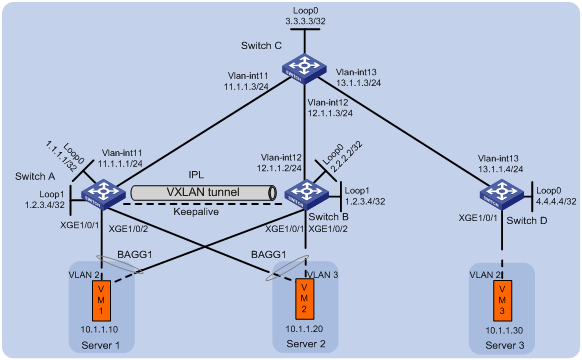
As shown in Figure 2, perform the following tasks to make sure the VMs can communicate with one another:
· Configure VXLAN 10 on Switch A, Switch B, and Switch D.
· Configure DRNI on Switch A and Switch B to virtualize them into one VTEP. Manually set up a VXLAN tunnel as the IPL between the switches.
· Configure Switch C as an RR.
Analysis
To make sure the overlay network has connectivity,, configure a routing protocol on these switches to advertise routes for reaching their interfaces, including the loopback interfaces. In this example, OSPF is used.
To conserve resources, configure Switch C to reflect routes for Switch A, Switch B, and Switch D.
Software versions used
This configuration example was created and verified on S6890 CMW710-R2712.
Restrictions and guidelines
In a DR system, DR member devices must have the same EVPN configuration.
As a best practice, use the IP address of a loopback interface as the virtual VTEP address.
You can configure only the following criteria for Ethernet service instances on DR interfaces:
· encapsulation s-vid { vlan-id | vlan-id-list }
· encapsulation untagged
As a best practice, do not redistribute external routes on the DR member devices.
You must disable spanning tree on the Layer 2 traffic outgoing interface for the VXLAN tunnel that acts as the IPL.
By default, interfaces on S6890 switches are disabled (in ADM or Administratively Down state). To have an interface operate, you must use the undo shutdown command to enable that interface.
Procedures
Configuring Layer 3 interfaces
# Configure the Layer 3 interfaces on Switch A.
<SwitchA> system-view
[SwitchA] interface loopback 0
[SwitchA-Loopback0] ip address 1.1.1.1 32
[SwitchA-Loopback0] quit
[SwitchA] interface loopback 1
[SwitchA-Loopback1] ip address 1.2.3.4 32
[SwitchA-Loopback1] quit
[SwitchA] vlan 11
[SwitchA-vlan11] port ten-gigabitethernet 1/0/5
[SwitchA-vlan11] quit
[SwitchA] interface vlan-interface 11
[SwitchA-Vlan-interface11] ip address 11.1.1.1 24
[SwitchA-Vlan-interface11] quit
# Configure the Layer 3 interfaces on other switches. (Details not shown.)
Configuring OSPF
Configuring Switch A
# Configure OSPF to advertise the networks attached to the Layer 3 interfaces.
[SwitchA] ospf 1 router-id 1.1.1.1
[SwitchA-ospf-1] area 0
[SwitchA-ospf-1-area-0.0.0.0] network 1.1.1.1 0.0.0.0
[SwitchA-ospf-1-area-0.0.0.0] network 1.2.3.4 0.0.0.0
[SwitchA-ospf-1-area-0.0.0.0] network 11.1.1.0 0.0.0.255
[SwitchA-ospf-1-area-0.0.0.0] quit
[SwitchA-ospf-1] quit
Configuring Switch B
# Configure OSPF to advertise the networks attached to the Layer 3 interfaces.
<SwitchB> system-view
[SwitchB] ospf 1 router-id 2.2.2.2
[SwitchB-ospf-1] area 0
[SwitchB-ospf-1-area-0.0.0.0] network 2.2.2.2 0.0.0.0
[SwitchB-ospf-1-area-0.0.0.0] network 1.2.3.4 0.0.0.0
[SwitchB-ospf-1-area-0.0.0.0] network 12.1.1.0 0.0.0.255
[SwitchB-ospf-1-area-0.0.0.0] quit
[SwitchB-ospf-1] quit
Configuring Switch C
# Configure OSPF to advertise the networks attached to the Layer 3 interfaces.
<SwitchC> system-view
[SwitchC] ospf 1 router-id 3.3.3.3
[SwitchC-ospf-1] area 0
[SwitchC-ospf-1-area-0.0.0.0] network 3.3.3.3 0.0.0.0
[SwitchC-ospf-1-area-0.0.0.0] network 11.1.1.0 0.0.0.255
[SwitchC-ospf-1-area-0.0.0.0] network 12.1.1.0 0.0.0.255
[SwitchC-ospf-1-area-0.0.0.0] network 13.1.1.0 0.0.0.255
[SwitchC-ospf-1-area-0.0.0.0] quit
[SwitchC-ospf-1] quit
Configuring Switch D
# Configure OSPF to advertise the networks attached to the Layer 3 interfaces.
<SwitchD> system-view
[SwitchD] ospf 1 router-id 4.4.4.4
[SwitchD-ospf-1] area 0
[SwitchD-ospf-1-area-0.0.0.0] network 4.4.4.4 0.0.0.0
[SwitchD-ospf-1-area-0.0.0.0] network 13.1.1.0 0.0.0.255
[SwitchD-ospf-1-area-0.0.0.0] quit
[SwitchD-ospf-1] quit
Configuring EVPN
Configuring Switch A
# Enable L2VPN.
[SwitchA] l2vpn enable
# Disable remote MAC address learning and remote ARP learning.
[SwitchA] vxlan tunnel mac-learning disable
[SwitchA] vxlan tunnel arp-learning disable
# Enable Layer 2 forwarding for VXLANs.
[SwitchA] undo vxlan ip-forwarding
# Specify the reserved VXLAN as VXLAN 1234.
[SwitchA] reserved vxlan 1234
# Create an EVPN instance on VSI vpna.
[SwitchA] vsi vpna
[SwitchA-vsi-vpna] arp suppression enable
[SwitchA-vsi-vpna] evpn encapsulation vxlan
# Configure the switch to automatically generate an RD and a route target for the EVPN instance.
[SwitchA-vsi-vpna-evpn-vxlan] route-distinguisher auto
[SwitchA-vsi-vpna-evpn-vxlan] vpn-target auto
[SwitchA-vsi-vpna-evpn-vxlan] quit
# Create VXLAN 10.
[SwitchA-vsi-vpna] vxlan 10
[SwitchA-vsi-vpna-vxlan-10] quit
[SwitchA-vsi-vpna] quit
Configuring Switch B
# Enable L2VPN.
[SwitchB] l2vpn enable
# Disable remote MAC address learning and remote ARP learning.
[SwitchB] vxlan tunnel mac-learning disable
[SwitchB] vxlan tunnel arp-learning disable
# Enable Layer 2 forwarding for VXLANs.
[SwitchB] undo vxlan ip-forwarding
# Specify the reserved VXLAN as VXLAN 1234.
[SwitchB] reserved vxlan 1234
# Create an EVPN instance on VSI vpna.
[SwitchB] vsi vpna
[SwitchB-vsi-vpna] arp suppression enable
[SwitchB-vsi-vpna] evpn encapsulation vxlan
# Configure the switch to automatically generate an RD and a route target for the EVPN instance.
[SwitchB-vsi-vpna-evpn-vxlan] route-distinguisher auto
[SwitchB-vsi-vpna-evpn-vxlan] vpn-target auto
[SwitchB-vsi-vpna-evpn-vxlan] quit
# Create VXLAN 10.
[SwitchB-vsi-vpna] vxlan 10
[SwitchB-vsi-vpna-vxlan-10] quit
[SwitchB-vsi-vpna] quit
Configuring Switch D
# Enable L2VPN.
[SwitchD] l2vpn enable
# Disable remote MAC address learning and remote ARP learning.
[SwitchD] vxlan tunnel mac-learning disable
[SwitchD] vxlan tunnel arp-learning disable
# Enable Layer 2 forwarding for VXLANs.
[SwitchD] undo vxlan ip-forwarding
# Create an EVPN instance on VSI vpna.
[SwitchD] vsi vpna
[SwitchD-vsi-vpna] arp suppression enable
[SwitchD-vsi-vpna] evpn encapsulation vxlan
# Configure the switch to automatically generate an RD and a route target for the EVPN instance.
[SwitchD-vsi-vpna-evpn-vxlan] route-distinguisher auto
[SwitchD-vsi-vpna-evpn-vxlan] vpn-target auto
[SwitchD-vsi-vpna-evpn-vxlan] quit
# Create VXLAN 10.
[SwitchD-vsi-vpna] vxlan 10
[SwitchD-vsi-vpna-vxlan-10] quit
[SwitchD-vsi-vpna] quit
Configuring DRNI
Configuring Switch A
# Specify the virtual VTEP address as 1.2.3.4.
[SwitchA] evpn drni group 1.2.3.4
# Configure DR system parameters.
[SwitchA] drni system-mac 0001-0001-0001
[SwitchA] drni system-number 1
[SwitchA] drni system-priority 10
[SwitchA] drni restore-delay 180
[SwitchA] drni keepalive ip destination 12.1.1.2 source 11.1.1.1
# Create a tunnel to Switch B, specify the tunnel interface as the IPP, and set the ToS of tunneled packets to 100.
[SwitchA] interface tunnel 1 mode vxlan
[SwitchA-Tunnel1] source 1.1.1.1
[SwitchA-Tunnel1] destination 2.2.2.2
[SwitchA-Tunnel1] port drni intra-portal-port 1
[SwitchA-Tunnel1] tunnel tos 100
[SwitchA-Tunnel1] quit
# Disable the static source check feature on Ten-GigabitEthernet 1/0/5.
[SwitchA] interface ten-gigabitethernet 1/0/5
[SwitchA-Ten-GigabitEthernet1/0/5] undo mac-address static source-check enable
[SwitchA-Ten-GigabitEthernet1/0/5] quit
# Create Layer 2 dynamic aggregate interface Bridge-Aggregation 4.
[SwitchA] interface bridge-aggregation 4
[SwitchA-Bridge-Aggregation4] link-aggregation mode dynamic
[SwitchA-Bridge-Aggregation4] quit
# Assign Ten-GigabitEthernet 1/0/1 to aggregation group 4.
[SwitchA] interface ten-gigabitethernet 1/0/1
[SwitchA-Ten-GigabitEthernet1/0/1] port link-aggregation group 4
[SwitchA-Ten-GigabitEthernet1/0/1] quit
# Assign Bridge-Aggregation 4 to DR group 4.
[SwitchA] interface bridge-aggregation 4
[SwitchA-Bridge-Aggregation4] port drni group 4
[SwitchA-Bridge-Aggregation4] quit
# Create Layer 2 dynamic aggregate interface Bridge-Aggregation 5.
[SwitchA] interface bridge-aggregation 5
[SwitchA-Bridge-Aggregation5] link-aggregation mode dynamic
[SwitchA-Bridge-Aggregation5] quit
# Assign Ten-GigabitEthernet 1/0/2 to aggregation group 5.
[SwitchA] interface ten-gigabitethernet 1/0/2
[SwitchA-Ten-GigabitEthernet1/0/2] port link-aggregation group 5
[SwitchA-Ten-GigabitEthernet1/0/2] quit
# Assign Bridge-Aggregation 5 to DR group 5.
[SwitchA] interface bridge-aggregation 5
[SwitchA-Bridge-Aggregation5] port drni group 5
[SwitchA-Bridge-Aggregation5] quit
# Exclude all interfaces used by EVPN from the shutdown action by DRNI MAD.
[SwitchA] mad exclude interface tunnel 1
[SwitchA] mad exclude interface loopback 0
[SwitchA] mad exclude interface ten-gigabitethernet 1/0/5
[SwitchA] mad exclude interface vlan-interface 11
Configuring Switch B
# Specify the virtual VTEP address as 1.2.3.4.
[SwitchB] evpn drni group 1.2.3.4
# Configure DR system parameters.
[SwitchB] drni system-mac 0001-0001-0001
[SwitchB] drni system-number 2
[SwitchB] drni system-priority 10
[SwitchB] drni restore-delay 180
[SwitchB] drni keepalive ip destination 11.1.1.1 source 12.1.1.2
# Create a tunnel to Switch A, specify the tunnel interface as the IPP, and set the ToS of tunneled packets to 100.
[SwitchB] interface tunnel 1 mode vxlan
[SwitchB-Tunnel1] source 2.2.2.2
[SwitchB-Tunnel1] destination 1.1.1.1
[SwitchB-Tunnel1] port drni intra-portal-port 1
[SwitchB-Tunnel1] tunnel tos 100
[SwitchB-Tunnel1] quit
# Disable the static source check feature on Ten-GigabitEthernet 1/0/5.
[SwitchB] interface ten-gigabitethernet 1/0/5
[SwitchB-Ten-GigabitEthernet1/0/5] undo mac-address static source-check enable
[SwitchB-Ten-GigabitEthernet1/0/5] quit
# Create Layer 2 dynamic aggregate interface Bridge-Aggregation 4.
[SwitchB] interface bridge-aggregation 4
[SwitchB-Bridge-Aggregation4] link-aggregation mode dynamic
[SwitchB-Bridge-Aggregation4] quit
# Assign Ten-GigabitEthernet 1/0/1 to aggregation group 4.
[SwitchB] interface ten-gigabitethernet 1/0/1
[SwitchB-Ten-GigabitEthernet1/0/1] port link-aggregation group 4
[SwitchB-Ten-GigabitEthernet1/0/1] quit
# Assign Bridge-Aggregation 4 to DR group 4.
[SwitchB] interface bridge-aggregation 4
[SwitchB-Bridge-Aggregation4] port drni group 4
[SwitchB-Bridge-Aggregation4] quit
# Create Layer 2 dynamic aggregate interface Bridge-Aggregation 5.
[SwitchB] interface bridge-aggregation 5
[SwitchB-Bridge-Aggregation5] link-aggregation mode dynamic
[SwitchB-Bridge-Aggregation5] quit
# Assign Ten-GigabitEthernet 1/0/2 to aggregation group 5.
[SwitchB] interface ten-gigabitethernet 1/0/2
[SwitchB-Ten-GigabitEthernet1/0/2] port link-aggregation group 5
[SwitchB-Ten-GigabitEthernet1/0/2] quit
# Assign Bridge-Aggregation 5 to DR group 5.
[SwitchB] interface bridge-aggregation 5
[SwitchB-Bridge-Aggregation5] port drni group 5
[SwitchB-Bridge-Aggregation5] quit
# Exclude all interfaces used by EVPN from the shutdown action by DRNI MAD.
[SwitchB] mad exclude interface tunnel 1
[SwitchB] mad exclude interface loopback 0
[SwitchB] mad exclude interface ten-gigabitethernet 1/0/5
[SwitchB] mad exclude interface vlan-interface 12
Configuring BGP to advertise BGP EVPN routes
Configuring Switch A
# Configure BGP to advertise BGP EVPN routes.
[SwitchA] bgp 200
[SwitchA-bgp-default] peer 3.3.3.3 as-number 200
[SwitchA-bgp-default] peer 3.3.3.3 connect-interface loopback 0
[SwitchA-bgp-default] address-family l2vpn evpn
[SwitchA-bgp-default-evpn] peer 3.3.3.3 enable
[SwitchA-bgp-default-evpn] quit
[SwitchA-bgp-default] quit
Configuring Switch B
# Configure BGP to advertise BGP EVPN routes.
[SwitchB] bgp 200
[SwitchB-bgp-default] peer 3.3.3.3 as-number 200
[SwitchB-bgp-default] peer 3.3.3.3 connect-interface loopback 0
[SwitchB-bgp-default] address-family l2vpn evpn
[SwitchB-bgp-default-evpn] peer 3.3.3.3 enable
[SwitchB-bgp-default-evpn] quit
[SwitchB-bgp-default] quit
Configuring Switch C
# Configure BGP to advertise BGP EVPN routes and configure the switch as an RR.
[SwitchC] bgp 200
[SwitchC-bgp-default] group evpn
[SwitchC-bgp-default] peer 1.1.1.1 group evpn
[SwitchC-bgp-default] peer 2.2.2.2 group evpn
[SwitchC-bgp-default] peer 4.4.4.4 group evpn
[SwitchC-bgp-default] peer evpn as-number 200
[SwitchC-bgp-default] peer evpn connect-interface loopback 0
[SwitchC-bgp-default] address-family l2vpn evpn
[SwitchC-bgp-default-evpn] peer evpn enable
[SwitchC-bgp-default-evpn] undo policy vpn-target
[SwitchC-bgp-default-evpn] peer evpn reflect-client
[SwitchC-bgp-default-evpn] quit
[SwitchC-bgp-default] quit
Configuring Switch D
# Configure BGP to advertise BGP EVPN routes.
[SwitchD] bgp 200
[SwitchD-bgp-default] peer 3.3.3.3 as-number 200
[SwitchD-bgp-default] peer 3.3.3.3 connect-interface loopback 0
[SwitchD-bgp-default] address-family l2vpn evpn
[SwitchD-bgp-default-evpn] peer 3.3.3.3 enable
[SwitchD-bgp-default-evpn] quit
[SwitchD-bgp-default] quit
Mapping Ethernet service instances to VSIs
Configuring Switch A
# On Bridge-Aggregation 4, create Ethernet service instance 1000 to match VLAN 2.
[SwitchA] interface bridge-aggregation 4
[SwitchA-Bridge-Aggregation4] service-instance 1000
[SwitchA-Bridge-Aggregation4-srv1000] encapsulation s-vid 2
# Map Ethernet service instance 1000 to VSI vpna.
[SwitchA-Bridge-Aggregation4-srv1000] xconnect vsi vpna
[SwitchA-Bridge-Aggregation4-srv1000] quit
# On Bridge-Aggregation 5, create Ethernet service instance 1000 to match VLAN 3.
[SwitchA] interface bridge-aggregation 5
[SwitchA-Bridge-Aggregation5] service-instance 1000
[SwitchA-Bridge-Aggregation5-srv1000] encapsulation s-vid 3
# Map Ethernet service instance 1000 to VSI vpna.
[SwitchA-Bridge-Aggregation5-srv1000] xconnect vsi vpna
[SwitchA-Bridge-Aggregation5-srv1000] quit
Configuring Switch B
# On Bridge-Aggregation 4, create Ethernet service instance 1000 to match VLAN 2.
[SwitchB] interface bridge-aggregation 4
[SwitchB-Bridge-Aggregation4] service-instance 1000
[SwitchB-Bridge-Aggregation4-srv1000] encapsulation s-vid 2
# Map Ethernet service instance 1000 to VSI vpna.
[SwitchB-Bridge-Aggregation4-srv1000] xconnect vsi vpna
[SwitchB-Bridge-Aggregation4-srv1000] quit
# On Bridge-Aggregation 5, create Ethernet service instance 1000 to match VLAN 3.
[SwitchB] interface bridge-aggregation 5
[SwitchB-Bridge-Aggregation5] service-instance 1000
[SwitchB-Bridge-Aggregation5-srv1000] encapsulation s-vid 3
# Map Ethernet service instance 1000 to VSI vpna.
[SwitchB-Bridge-Aggregation5-srv1000] xconnect vsi vpna
[SwitchB-Bridge-Aggregation5-srv1000] quit
Configuring Switch D
# On Ten-GigabitEthernet 1/0/1, create Ethernet service instance 1000 to match VLAN 2.
[SwitchD] interface ten-gigabitethernet 1/0/1
[SwitchD-Ten-GigabitEthernet1/0/1] service-instance 1000
[SwitchD-Ten-GigabitEthernet1/0/1] encapsulation s-vid 2
# Map Ethernet service instance 1000 to VSI vpna.
[SwitchD-Ten-GigabitEthernet1/0/1] xconnect vsi vpna
[SwitchD-Ten-GigabitEthernet1/0/1] quit
Verifying the configuration
Verifying the configuration on a DR member device
The verification procedure uses Switch A as an example.
# Verify that Switch A has BGP EVPN routes.
[Switch A]display bgp l2vpn evpn
BGP local router ID is 1.2.3.4
Status codes: * - valid, > - best, d - dampened, h - history
s - suppressed, S - stale, i - internal, e - external
a - additional-path
Origin: i - IGP, e - EGP, ? - incomplete
Total number of routes from all PEs: 2
Route distinguisher: 1:10
Total number of routes: 4
Network NextHop MED LocPrf PrefVal Path/Ogn
* > [3][0][32][1.1.1.1]/80
1.1.1.1 0 100 32768 i
* > [3][0][32][1.2.3.4]/80
1.2.3.4 0 100 32768 i
* >i [3][0][32][2.2.2.2]/80
2.2.2.2 0 100 0 i
* >i [3][0][32][4.4.4.4]/80
4.4.4.4 0 100 0 i
# Verify that the IPL Tunnel 1 is up, and Tunnel 0 to Switch D uses the virtual VTEP address as the source address.
[SwitchA] display interface Tunnel
Tunnel0
Current state: UP
Line protocol state: UP
Description: Tunnel0 Interface
Bandwidth: 64 kbps
Maximum transmission unit: 1464
Internet protocol processing: Disabled
Last clearing of counters: Never
Tunnel source 1.2.3.4, destination 4.4.4.4
Tunnel protocol/transport UDP_VXLAN/IP
Last 300 seconds input rate: 0 bytes/sec, 0 bits/sec, 0 packets/sec
Last 300 seconds output rate: 0 bytes/sec, 0 bits/sec, 0 packets/sec
Input: 0 packets, 0 bytes, 0 drops
Output: 0 packets, 0 bytes, 0 drops
Tunnel1
Current state: UP
Line protocol state: UP
Description: Tunnel1 Interface
Bandwidth: 64 kbps
Maximum transmission unit: 1464
Internet protocol processing: Disabled
Last clearing of counters: Never
Tunnel source 1.1.1.1, destination 2.2.2.2
Tunnel protocol/transport UDP_VXLAN/IP
Last 300 seconds input rate: 13 bytes/sec, 104 bits/sec, 0 packets/sec
Last 300 seconds output rate: 13 bytes/sec, 104 bits/sec, 0 packets/sec
Input: 332 packets, 36377 bytes, 0 drops
Output: 583 packets, 59132 bytes, 0 drops
# Verify that the VXLAN tunnels have been assigned to VXLAN 10.
[SwitchA] display l2vpn vsi verbose
VSI Name: vpna
VSI Index : 0
VSI State : Up
MTU : 1500
Bandwidth : Unlimited
Broadcast Restrain : Unlimited
Multicast Restrain : Unlimited
Unknown Unicast Restrain: Unlimited
MAC Learning : Enabled
MAC Table Limit : -
MAC Learning rate : -
Drop Unknown : -
Flooding : Enabled
Statistics : Disabled
VXLAN ID : 10
Tunnels:
Tunnel Name Link ID State Type Flood proxy
Tunnel0 0x5000000 UP Auto Disabled
Tunnel1 0x5000001 UP Manual Disabled
ACs:
AC Link ID State Type
BAGG4 srv1000 0 Up Manual
BAGG5 srv1000 2 Up Manual
Verifying the network connectivity of the VMs
# Verify that VM 1, VM 2, and VM 3 can communicate when both Switch A and Switch B are operating correctly. (Details not shown.)
# Verify that VM 1, VM 2, and VM 3 can communicate when Switch A's or Switch B's links to the local site are disconnected. (Details not shown.)
Configuration files
· Switch A:
#
undo vxlan ip-forwarding
#
vxlan tunnel mac-learning disable
#
ospf 1 router-id 1.1.1.1
area 0.0.0.0
network 1.1.1.1 0.0.0.0
network 1.2.3.4 0.0.0.0
network 11.1.1.0 0.0.0.255
#
vlan 11
#
l2vpn enable
reserved vxlan 1234
vxlan tunnel arp-learning disable
evpn drni group 1.2.3.4
#
vsi vpna
arp suppression enable
vxlan 10
evpn encapsulation vxlan
route-distinguisher auto
vpn-target auto export-extcommunity
vpn-target auto import-extcommunity
#
interface Bridge-Aggregation4
link-aggregation mode dynamic
port drni group 4
#
service-instance 1000
encapsulation s-vid 2
xconnect vsi vpna
#
interface Bridge-Aggregation5
link-aggregation mode dynamic
port drni group 5
#
service-instance 1000
encapsulation s-vid 3
xconnect vsi vpna
#
interface LoopBack0
ip address 1.1.1.1 255.255.255.255
#
interface LoopBack1
ip address 1.2.3.4 255.255.255.255
#
interface Vlan-interface11
ip address 11.1.1.1 255.255.255.0
#
interface Ten-GigabitEthernet1/0/1
port link-mode bridge
port link-aggregation group 4
#
interface Ten-GigabitEthernet1/0/2
port link-mode bridge
port link-aggregation group 5
#
interface Ten-GigabitEthernet1/0/5
port link-mode bridge
port access vlan 11
undo mac-address static source-check enable
#
interface Tunnel1 mode vxlan
port drni intra-portal-port 1
source 1.1.1.1
destination 2.2.2.2
tunnel tos 100
#
bgp 200
peer 3.3.3.3 as-number 200
peer 3.3.3.3 connect-interface LoopBack0
#
address-family l2vpn evpn
peer 3.3.3.3 enable
#
drni keepalive ip destination 12.1.1.2 source 11.1.1.1
drni restore-delay 180
drni system-mac 0001-0001-0001
drni system-number 1
drni system-priority 10
#
mad exclude interface LoopBack0
mad exclude interface Ten-GigabitEthernet1/0/5
mad exclude interface Tunnel1
mad exclude interface Vlan-interface 11
#
return
· Switch B:
#
undo vxlan ip-forwarding
#
vxlan tunnel mac-learning disable
#
ospf 1 router-id 2.2.2.2
area 0.0.0.0
network 1.2.3.4 0.0.0.0
network 2.2.2.2 0.0.0.0
network 12.1.1.0 0.0.0.255
#
vlan 12
#
l2vpn enable
reserved vxlan 1234
evpn drni group 1.2.3.4
vxlan tunnel arp-learning disable
#
vsi vpna
arp suppression enable
vxlan 10
evpn encapsulation vxlan
route-distinguisher auto
vpn-target auto export-extcommunity
vpn-target auto import-extcommunity
#
interface Bridge-Aggregation4
link-aggregation mode dynamic
port drni group 4
#
service-instance 1000
encapsulation s-vid 2
xconnect vsi vpna
#
interface Bridge-Aggregation5
link-aggregation mode dynamic
port drni group 5
#
service-instance 1000
encapsulation s-vid 3
xconnect vsi vpna
#
interface LoopBack0
ip address 2.2.2.2 255.255.255.255
#
interface LoopBack1
ip address 1.2.3.4 255.255.255.255
#
interface Vlan-interface12
ip address 12.1.1.2 255.255.255.0
#
interface Ten-GigabitEthernet1/0/1
port link-mode bridge
port link-aggregation group 4
#
interface Ten-GigabitEthernet1/0/2
port link-mode bridge
port link-aggregation group 5
#
interface Ten-GigabitEthernet1/0/5
port link-mode bridge
port access vlan 12
undo mac-address static source-check enable
#
interface Tunnel1 mode vxlan
port drni intra-portal-port 1
source 2.2.2.2
destination 1.1.1.1
tunnel tos 100
#
bgp 200
peer 3.3.3.3 as-number 200
peer 3.3.3.3 connect-interface LoopBack0
#
address-family l2vpn evpn
peer 3.3.3.3 enable
#
drni keepalive ip destination 11.1.1.1 source 12.1.1.2
drni restore-delay 180
drni system-mac 0001-0001-0001
drni system-number 2
drni system-priority 10
#
mad exclude interface LoopBack0
mad exclude interface Ten-GigabitEthernet1/0/5
mad exclude interface Tunnel1
mad exclude interface Vlan-interface 12
#
return
· Switch C:
#
ospf 1 router-id 3.3.3.3
area 0.0.0.0
network 3.3.3.3 0.0.0.0
network 11.1.1.0 0.0.0.255
network 12.1.1.0 0.0.0.255
network 13.1.1.0 0.0.0.255
#
vlan 11 to 13
#
interface LoopBack0
ip address 3.3.3.3 255.255.255.255
#
interface Vlan-interface11
ip address 11.1.1.3 255.255.255.0
#
interface Vlan-interface12
ip address 12.1.1.3 255.255.255.0
#
interface Vlan-interface13
ip address 13.1.1.3 255.255.255.0
#
interface Ten-GigabitEthernet1/0/1
port link-mode bridge
port access vlan 11
#
interface Ten-GigabitEthernet1/0/2
port link-mode bridge
port access vlan 12
#
interface Ten-GigabitEthernet1/0/3
port link-mode bridge
port access vlan 13
#
bgp 200
group evpn internal
peer evpn connect-interface LoopBack0
peer 1.1.1.1 group evpn
peer 2.2.2.2 group evpn
peer 4.4.4.4 group evpn
#
address-family l2vpn evpn
undo policy vpn-target
peer evpn enable
peer evpn reflect-client
#
return
· Switch D:
#
undo vxlan ip-forwarding
#
vxlan tunnel mac-learning disable
#
ospf 1 router-id 4.4.4.4
area 0.0.0.0
network 4.4.4.4 0.0.0.0
network 13.1.1.0 0.0.0.255
#
vlan 13
#
l2vpn enable
vxlan tunnel arp-learning disable
#
vsi vpna
arp suppression enable
vxlan 10
evpn encapsulation vxlan
route-distinguisher auto
vpn-target auto export-extcommunity
vpn-target auto import-extcommunity
#
interface LoopBack0
ip address 4.4.4.4 255.255.255.255
#
interface Vlan-interface13
ip address 13.1.1.4 255.255.255.0
#
interface Ten-GigabitEthernet1/0/1
port link-mode bridge
#
service-instance 1000
encapsulation s-vid 2
xconnect vsi vpna
#
interface Ten-GigabitEthernet1/0/2
port link-mode bridge
port access vlan 13
#
bgp 200
peer 3.3.3.3 as-number 200
peer 3.3.3.3 connect-interface LoopBack0
#
address-family l2vpn evpn
peer 3.3.3.3 enable
#
return
Example: Configuring DRNI using an Ethernet aggregate link as the IPL on EVPN gateways
Network configuration
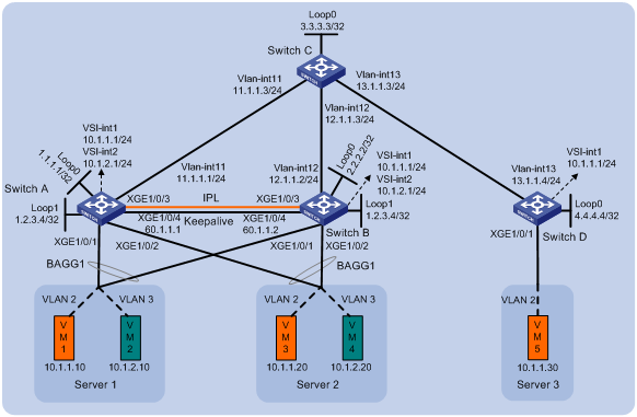
As shown in Figure 3, perform the following tasks to make sure the VMs can communicate with one another:
· Configure VXLAN 10 on Switch A, Switch B, and Switch D, and configure VXLAN 20 on Switch A and Switch B.
· Configure Switch A, Switch B, and Switch D as distributed EVPN gateways to provide Layer 3 forwarding service for VMs.
· Configure DRNI on Switch A and Switch B to virtualize them into one VTEP. Configure an Ethernet aggregate link as the IPL between the switches.
· Configure Switch C as an RR.
Analysis
To make sure the overlay network has connectivity,, configure a routing protocol on these switches to advertise routes for reaching their interfaces, including the loopback interfaces. In this example, OSPF is used.
To conserve resources, configure Switch C to reflect routes for Switch A, Switch B, and Switch D.
Software versions used
This configuration example was created and verified on S6890 CMW710-R2712.
Restrictions and guidelines
In a DR system, DR member devices must have the same EVPN configuration.
Make sure the outer VLAN IDs configured on Ethernet service instances of different VSIs do not overlap. The Ethernet service interfaces that match the same outer VLAN ID on different ports must be mapped to the same VSI.
For EVPN to run correctly on a DR system, you must execute the undo mac-address static source-check enable command on IPPs and IRF physical interfaces of the DR member devices.
As a best practice, use the IP address of a loopback interface as the virtual VTEP address.
By default, interfaces on S6890 switches are disabled (in ADM or Administratively Down state). To have an interface operate, you must use the undo shutdown command to enable that interface.
Procedures
Configuring Layer 3 interfaces
# Configure the Layer 3 interfaces on Switch A.
<SwitchA> system-view
[SwitchA] interface loopback 0
[SwitchA-Loopback0] ip address 1.1.1.1 32
[SwitchA-Loopback0] quit
[SwitchA] interface loopback 1
[SwitchA-Loopback1] ip address 1.2.3.4 32
[SwitchA-Loopback1] quit
[SwitchA] vlan 11
[SwitchA-vlan11] port ten-gigabitethernet 1/0/5
[SwitchA-vlan11] quit
[SwitchA] interface vlan-interface 11
[SwitchA-Vlan-interface11] ip address 11.1.1.1 24
[SwitchA-Vlan-interface11] quit
[SwitchA] interface ten-gigabitethernet 1/0/4
[SwitchA-Ten-GigabitEthernet1/0/4] port link-mode route
[SwitchA-Ten-GigabitEthernet1/0/4] ip address 60.1.1.1 24
[SwitchA-Ten-GigabitEthernet1/0/4] quit
# Configure the Layer 3 interfaces on other switches. (Details not shown.)
# On VM 1, VM 3, and VM 5, specify 10.1.1.1 as the gateway address. On VM 2 and VM 4, specify 10.1.2.1 as the gateway address. (Details not shown.)
Configuring OSPF
Configuring Switch A
# Configure OSPF to advertise the networks attached to the Layer 3 interfaces.
[SwitchA] ospf 1 router-id 1.1.1.1
[SwitchA-ospf-1] area 0
[SwitchA-ospf-1-area-0.0.0.0] network 1.1.1.1 0.0.0.0
[SwitchA-ospf-1-area-0.0.0.0] network 1.2.3.4 0.0.0.0
[SwitchA-ospf-1-area-0.0.0.0] network 11.1.1.0 0.0.0.255
[SwitchA-ospf-1-area-0.0.0.0] quit
[SwitchA-ospf-1] quit
Configuring Switch B
# Configure OSPF to advertise the networks attached to the Layer 3 interfaces.
<SwitchB> system-view
[SwitchB] ospf 1 router-id 2.2.2.2
[SwitchB-ospf-1] area 0
[SwitchB-ospf-1-area-0.0.0.0] network 2.2.2.2 0.0.0.0
[SwitchB-ospf-1-area-0.0.0.0] network 1.2.3.4 0.0.0.0
[SwitchB-ospf-1-area-0.0.0.0] network 12.1.1.0 0.0.0.255
[SwitchB-ospf-1-area-0.0.0.0] quit
[SwitchB-ospf-1] quit
Configuring Switch C
# Configure OSPF to advertise the networks attached to the Layer 3 interfaces.
<SwitchC> system-view
[SwitchC] ospf 1 router-id 3.3.3.3
[SwitchC-ospf-1] area 0
[SwitchC-ospf-1-area-0.0.0.0] network 3.3.3.3 0.0.0.0
[SwitchC-ospf-1-area-0.0.0.0] network 11.1.1.0 0.0.0.255
[SwitchC-ospf-1-area-0.0.0.0] network 12.1.1.0 0.0.0.255
[SwitchC-ospf-1-area-0.0.0.0] network 13.1.1.0 0.0.0.255
[SwitchC-ospf-1-area-0.0.0.0] quit
[SwitchC-ospf-1] quit
Configuring Switch D
# Configure OSPF to advertise the networks attached to the Layer 3 interfaces.
<SwitchD> system-view
[SwitchD] ospf 1 router-id 4.4.4.4
[SwitchD-ospf-1] area 0
[SwitchD-ospf-1-area-0.0.0.0] network 4.4.4.4 0.0.0.0
[SwitchD-ospf-1-area-0.0.0.0] network 13.1.1.0 0.0.0.255
[SwitchD-ospf-1-area-0.0.0.0] quit
[SwitchD-ospf-1] quit
Configuring EVPN
Configuring Switch A
# Enable L2VPN.
[SwitchA] l2vpn enable
# Disable remote MAC address learning and remote ARP learning.
[SwitchA] vxlan tunnel mac-learning disable
[SwitchA] vxlan tunnel arp-learning disable
# Configure the EVPN global MAC address as 0002-0003-0004.
[SwitchA] evpn global-mac 2-3-4
# Create an EVPN instance on VSI vpna.
[SwitchA] vsi vpna
[SwitchA-vsi-vpna] evpn encapsulation vxlan
# Configure the switch to automatically generate an RD and a route target for the EVPN instance.
[SwitchA-vsi-vpna-evpn-vxlan] route-distinguisher auto
[SwitchA-vsi-vpna-evpn-vxlan] vpn-target auto
[SwitchA-vsi-vpna-evpn-vxlan] quit
# Create VXLAN 10.
[SwitchA-vsi-vpna] vxlan 10
[SwitchA-vsi-vpna-vxlan-10] quit
[SwitchA-vsi-vpna] quit
# Create an EVPN instance on VSI vpnb.
[SwitchA] vsi vpnb
[SwitchA-vsi-vpnb] evpn encapsulation vxlan
# Configure the switch to automatically generate an RD and a route target for the EVPN instance.
[SwitchA-vsi-vpnb-evpn-vxlan] route-distinguisher auto
[SwitchA-vsi-vpnb-evpn-vxlan] vpn-target auto
[SwitchA-vsi-vpnb-evpn-vxlan] quit
# Create VXLAN 20.
[SwitchA-vsi-vpnb] vxlan 20
[SwitchA-vsi-vpnb-vxlan-20] quit
[SwitchA-vsi-vpnb] quit
Configuring Switch B
# Enable L2VPN.
[SwitchB] l2vpn enable
# Disable remote MAC address learning and remote ARP learning.
[SwitchB] vxlan tunnel mac-learning disable
[SwitchB] vxlan tunnel arp-learning disable
# Configure the EVPN global MAC address as 0002-0003-0004.
[SwitchB] evpn global-mac 2-3-4
# Create an EVPN instance on VSI vpna.
[SwitchB] vsi vpna
[SwitchB-vsi-vpna] evpn encapsulation vxlan
# Configure the switch to automatically generate an RD and a route target for the EVPN instance.
[SwitchB-vsi-vpna-evpn-vxlan] route-distinguisher auto
[SwitchB-vsi-vpna-evpn-vxlan] vpn-target auto
[SwitchB-vsi-vpna-evpn-vxlan] quit
# Create VXLAN 10.
[SwitchB-vsi-vpna] vxlan 10
[SwitchB-vsi-vpna-vxlan-10] quit
[SwitchB-vsi-vpna] quit
# Create an EVPN instance on VSI vpnb.
[SwitchB] vsi vpnb
[SwitchB-vsi-vpnb] evpn encapsulation vxlan
# Configure the switch to automatically generate an RD and a route target for the EVPN instance.
[SwitchB-vsi-vpnb-evpn-vxlan] route-distinguisher auto
[SwitchB-vsi-vpnb-evpn-vxlan] vpn-target auto
[SwitchB-vsi-vpnb-evpn-vxlan] quit
# Create VXLAN 20.
[SwitchB-vsi-vpnb] vxlan 20
[SwitchB-vsi-vpnb-vxlan-20] quit
[SwitchB-vsi-vpnb] quit
Configuring Switch D
# Enable L2VPN.
[SwitchD] l2vpn enable
# Disable remote MAC address learning and remote ARP learning.
[SwitchD] vxlan tunnel mac-learning disable
[SwitchD] vxlan tunnel arp-learning disable
# Create an EVPN instance on VSI vpna.
[SwitchD] vsi vpna
[SwitchD-vsi-vpna] evpn encapsulation vxlan
# Configure the switch to automatically generate an RD and a route target for the EVPN instance.
[SwitchD-vsi-vpna-evpn-vxlan] route-distinguisher auto
[SwitchD-vsi-vpna-evpn-vxlan] vpn-target auto
[SwitchD-vsi-vpna-evpn-vxlan] quit
# Create VXLAN 10.
[SwitchD-vsi-vpna] vxlan 10
[SwitchD-vsi-vpna-vxlan-10] quit
[SwitchD-vsi-vpna] quit
Configuring distributed EVPN gateways
Configuring Switch A
# Configure RD and route target settings for VPN instance vpna.
[SwitchA] ip vpn-instance vpna
[SwitchA-vpn-instance-vpna] route-distinguisher 1:1
[SwitchA-vpn-instance-vpna] address-family ipv4
[SwitchA-vpn-ipv4-vpna] vpn-target 2:2
[SwitchA-vpn-ipv4-vpna] quit
[SwitchA-vpn-instance-vpna] address-family evpn
[SwitchA-vpn-evpn-vpna] vpn-target 1:1
[SwitchA-vpn-evpn-vpna] quit
[SwitchA-vpn-instance-vpna] quit
# Configure VSI-interface 1 as a distributed gateway.
[SwitchA] interface vsi-interface 1
[SwitchA-Vsi-interface1] ip binding vpn-instance vpna
[SwitchA-Vsi-interface1] ip address 10.1.1.1 255.255.255.0
[SwitchA-Vsi-interface1] mac-address 1-1-1
[SwitchA-Vsi-interface1] distributed-gateway local
[SwitchA-Vsi-interface1] local-proxy-arp enable
[SwitchA-Vsi-interface1] quit
# Configure VSI-interface 2 as a distributed gateway.
[SwitchA] interface vsi-interface 2
[SwitchA-Vsi-interface2] ip binding vpn-instance vpna
[SwitchA-Vsi-interface2] ip address 10.1.2.1 255.255.255.0
[SwitchA-Vsi-interface2] mac-address 2-2-2
[SwitchA-Vsi-interface2] distributed-gateway local
[SwitchA-Vsi-interface2] local-proxy-arp enable
[SwitchA-Vsi-interface2] quit
# Create VSI-interface 3. Associate VSI-interface 3 with VPN instance vpna, and configure the L3 VXLAN ID as 1000 for the VPN instance.
[SwitchA] interface vsi-interface 3
[SwitchA-Vsi-interface3] ip binding vpn-instance vpna
[SwitchA-Vsi-interface3] l3-vni 1000
[SwitchA-Vsi-interface3] quit
# Specify VSI-interface 1 as the gateway interface for VSI vpna.
[SwitchA] vsi vpna
[SwitchA-vsi-vpna] gateway vsi-interface 1
[SwitchA-vsi-vpna] quit
# Specify VSI-interface 2 as the gateway interface for VSI vpnb.
[SwitchA] vsi vpnb
[SwitchA-vsi-vpnb] gateway vsi-interface 2
[SwitchA-vsi-vpnb] quit
Configuring Switch B
# Configure RD and route target settings for VPN instance vpna.
[SwitchB] ip vpn-instance vpna
[SwitchB-vpn-instance-vpna] route-distinguisher 1:1
[SwitchB-vpn-instance-vpna] address-family ipv4
[SwitchB-vpn-ipv4-vpna] vpn-target 2:2
[SwitchB-vpn-ipv4-vpna] quit
[SwitchB-vpn-instance-vpna] address-family evpn
[SwitchB-vpn-evpn-vpna] vpn-target 1:1
[SwitchB-vpn-evpn-vpna] quit
[SwitchB-vpn-instance-vpna] quit
# Configure VSI-interface 1 as a distributed gateway.
[SwitchB] interface vsi-interface 1
[SwitchB-Vsi-interface1] ip binding vpn-instance vpna
[SwitchB-Vsi-interface1] ip address 10.1.1.1 255.255.255.0
[SwitchB-Vsi-interface1] mac-address 1-1-1
[SwitchB-Vsi-interface1] distributed-gateway local
[SwitchB-Vsi-interface1] local-proxy-arp enable
[SwitchB-Vsi-interface1] quit
# Configure VSI-interface 2 as a distributed gateway.
[SwitchB] interface vsi-interface 2
[SwitchB-Vsi-interface2] ip binding vpn-instance vpna
[SwitchB-Vsi-interface2] ip address 10.1.2.1 255.255.255.0
[SwitchB-Vsi-interface2] mac-address 2-2-2
[SwitchB-Vsi-interface2] distributed-gateway local
[SwitchB-Vsi-interface2] local-proxy-arp enable
[SwitchB-Vsi-interface2] quit
# Create VSI-interface 3. Associate VSI-interface 3 with VPN instance vpna, and configure the L3 VXLAN ID as 1000 for the VPN instance.
[SwitchB] interface vsi-interface 3
[SwitchB-Vsi-interface3] ip binding vpn-instance vpna
[SwitchB-Vsi-interface3] l3-vni 1000
[SwitchB-Vsi-interface3] quit
# Specify VSI-interface 1 as the gateway interface for VSI vpna.
[SwitchB] vsi vpna
[SwitchB-vsi-vpna] gateway vsi-interface 1
[SwitchB-vsi-vpna] quit
# Specify VSI-interface 2 as the gateway interface for VSI vpnb.
[SwitchB] vsi vpnb
[SwitchB-vsi-vpnb] gateway vsi-interface 2
[SwitchB-vsi-vpnb] quit
Configuring Switch D
# Configure RD and route target settings for VPN instance vpna.
[SwitchD] ip vpn-instance vpna
[SwitchD-vpn-instance-vpna] route-distinguisher 1:1
[SwitchD-vpn-instance-vpna] address-family ipv4
[SwitchD-vpn-ipv4-vpna] vpn-target 2:2
[SwitchD-vpn-ipv4-vpna] quit
[SwitchD-vpn-instance-vpna] address-family evpn
[SwitchD-vpn-evpn-vpna] vpn-target 1:1
[SwitchD-vpn-evpn-vpna] quit
[SwitchD-vpn-instance-vpna] quit
# Configure VSI-interface 1 as a distributed gateway.
[SwitchD] interface vsi-interface 1
[SwitchD-Vsi-interface1] ip binding vpn-instance vpna
[SwitchD-Vsi-interface1] ip address 10.1.1.1 255.255.255.0
[SwitchD-Vsi-interface1] mac-address 1-1-1
[SwitchD-Vsi-interface1] distributed-gateway local
[SwitchD-Vsi-interface1] local-proxy-arp enable
[SwitchD-Vsi-interface1] quit
# Create VSI-interface 3. Associate VSI-interface 3 with VPN instance vpna and configure the L3 VXLAN ID as 1000 for the VPN instance.
[SwitchD] interface vsi-interface 3
[SwitchD-Vsi-interface3] ip binding vpn-instance vpna
[SwitchD-Vsi-interface3] l3-vni 1000
[SwitchD-Vsi-interface3] quit
# Specify VSI-interface 1 as the gateway interface for VSI vpna.
[SwitchD] vsi vpna
[SwitchD-vsi-vpna] gateway vsi-interface 1
[SwitchD-vsi-vpna] quit
Configuring DRNI
Configuring Switch A
# Specify the virtual VTEP address as 1.2.3.4.
[SwitchA] evpn drni group 1.2.3.4
# Configure DR system parameters.
[SwitchA] drni system-mac 0001-0002-0003
[SwitchA] drni system-number 1
[SwitchA] drni system-priority 10
[SwitchA] drni restore-delay 180
[SwitchA] drni keepalive ip destination 60.1.1.2 source 60.1.1.1
# Create Layer 2 dynamic aggregate interface Bridge-Aggregation 3.
[SwitchA] interface bridge-aggregation 3
[SwitchA-Bridge-Aggregation3] link-aggregation mode dynamic
[SwitchA-Bridge-Aggregation3] quit
# Assign Ten-GigabitEthernet 1/0/3 to aggregation group 3.
[SwitchA] interface ten-gigabitethernet 1/0/3
[SwitchA-Ten-GigabitEthernet1/0/3] port link-aggregation group 3
[SwitchA-Ten-GigabitEthernet1/0/3] quit
# Specify Bridge-Aggregation 3 as the IPP.
[SwitchA] interface bridge-aggregation 3
[SwitchA-Bridge-Aggregation3] port drni intra-portal-port 1
[SwitchA-Bridge-Aggregation3] undo mac-address static source-check enable
[SwitchA-Bridge-Aggregation3] quit
# Disable the static source check feature on Ten-GigabitEthernet 1/0/5.
[SwitchA] interface ten-gigabitethernet 1/0/5
[SwitchA-Ten-GigabitEthernet1/0/5] undo mac-address static source-check enable
[SwitchA-Ten-GigabitEthernet1/0/5] quit
# Create Layer 2 dynamic aggregate interface Bridge-Aggregation 4.
[SwitchA] interface bridge-aggregation 4
[SwitchA-Bridge-Aggregation4] link-aggregation mode dynamic
[SwitchA-Bridge-Aggregation4] quit
# Assign Ten-GigabitEthernet 1/0/1 to aggregation group 4.
[SwitchA] interface ten-gigabitethernet 1/0/1
[SwitchA-Ten-GigabitEthernet1/0/1] port link-aggregation group 4
[SwitchA-Ten-GigabitEthernet1/0/1] quit
# Assign Bridge-Aggregation 4 to DR group 4.
[SwitchA] interface bridge-aggregation 4
[SwitchA-Bridge-Aggregation4] port drni group 4
[SwitchA-Bridge-Aggregation4] quit
# Create Layer 2 dynamic aggregate interface Bridge-Aggregation 5.
[SwitchA] interface bridge-aggregation 5
[SwitchA-Bridge-Aggregation5] link-aggregation mode dynamic
[SwitchA-Bridge-Aggregation5] quit
# Assign Ten-GigabitEthernet 1/0/2 to aggregation group 5.
[SwitchA] interface ten-gigabitethernet 1/0/2
[SwitchA-Ten-GigabitEthernet1/0/2] port link-aggregation group 5
[SwitchA-Ten-GigabitEthernet1/0/2] quit
# Assign Bridge-Aggregation 5 to DR group 5.
[SwitchA] interface bridge-aggregation 5
[SwitchA-Bridge-Aggregation5] port drni group 5
[SwitchA-Bridge-Aggregation5] quit
# Exclude all interfaces used by EVPN from the shutdown action by DRNI MAD.
[SwitchA] mad exclude interface loopback 0
[SwitchA] mad exclude interface ten-gigabitethernet 1/0/4
[SwitchA] mad exclude interface ten-gigabitethernet 1/0/5
[SwitchA] mad exclude interface vlan-interface 11
[SwitchA] mad exclude interface vsi-interface 1
[SwitchA] mad exclude interface vsi-interface 2
Configuring Switch B
# Specify the virtual VTEP address as 1.2.3.4.
[SwitchB] evpn drni group 1.2.3.4
# Configure DR system parameters.
[SwitchB] drni system-mac 0001-0002-0003
[SwitchB] drni system-number 2
[SwitchB] drni system-priority 10
[SwitchB] drni restore-delay 180
[SwitchB] drni keepalive ip destination 60.1.1.1 source 60.1.1.2
# Create Layer 2 dynamic aggregate interface Bridge-Aggregation 3.
[SwitchB] interface bridge-aggregation 3
[SwitchB-Bridge-Aggregation3] link-aggregation mode dynamic
[SwitchB-Bridge-Aggregation3] quit
# Assign Ten-GigabitEthernet 1/0/3 to aggregation group 3.
[SwitchB] interface ten-gigabitethernet 1/0/3
[SwitchB-Ten-GigabitEthernet1/0/3] port link-aggregation group 3
[SwitchB-Ten-GigabitEthernet1/0/3] quit
# Specify Bridge-Aggregation 3 as the IPP.
[SwitchB] interface bridge-aggregation 3
[SwitchB-Bridge-Aggregation3] port drni intra-portal-port 1
[SwitchB-Bridge-Aggregation3] undo mac-address static source-check enable
[SwitchB-Bridge-Aggregation3] quit
# Disable the static source check feature on Ten-GigabitEthernet 1/0/5.
[SwitchB] interface ten-gigabitethernet 1/0/5
[SwitchB-Ten-GigabitEthernet1/0/5] undo mac-address static source-check enable
[SwitchB-Ten-GigabitEthernet1/0/5] quit
# Create Layer 2 dynamic aggregate interface Bridge-Aggregation 4.
[SwitchB] interface bridge-aggregation 4
[SwitchB-Bridge-Aggregation4] link-aggregation mode dynamic
[SwitchB-Bridge-Aggregation4] quit
# Assign Ten-GigabitEthernet 1/0/1 to aggregation group 4.
[SwitchB] interface ten-gigabitethernet 1/0/1
[SwitchB-Ten-GigabitEthernet1/0/1] port link-aggregation group 4
[SwitchB-Ten-GigabitEthernet1/0/1] quit
# Assign Bridge-Aggregation 4 to DR group 4.
[SwitchB] interface bridge-aggregation 4
[SwitchB-Bridge-Aggregation4] port drni group 4
[SwitchB-Bridge-Aggregation4] quit
# Create Layer 2 dynamic aggregate interface Bridge-Aggregation 5.
[SwitchB] interface bridge-aggregation 5
[SwitchB-Bridge-Aggregation5] link-aggregation mode dynamic
[SwitchB-Bridge-Aggregation5] quit
# Assign Ten-GigabitEthernet 1/0/2 to aggregation group 5.
[SwitchB] interface ten-gigabitethernet 1/0/2
[SwitchB-Ten-GigabitEthernet1/0/2] port link-aggregation group 5
[SwitchB-Ten-GigabitEthernet1/0/2] quit
# Assign Bridge-Aggregation 5 to DR group 5.
[SwitchB] interface bridge-aggregation 5
[SwitchB-Bridge-Aggregation5] port drni group 5
[SwitchB-Bridge-Aggregation5] quit
# Exclude all interfaces used by EVPN from the shutdown action by DRNI MAD.
[SwitchB] mad exclude interface loopback 0
[SwitchB] mad exclude interface ten-gigabitethernet 1/0/4
[SwitchB] mad exclude interface ten-gigabitethernet 1/0/5
[SwitchB] mad exclude interface vsi-interface 1
[SwitchB] mad exclude interface vsi-interface 2
[SwitchB] mad exclude interface vlan-interface 12
Configuring BGP to advertise BGP EVPN routes
Configuring Switch A
# Configure BGP to advertise BGP EVPN routes.
[SwitchA] bgp 200
[SwitchA-bgp-default] peer 3.3.3.3 as-number 200
[SwitchA-bgp-default] peer 3.3.3.3 connect-interface loopback 0
[SwitchA-bgp-default] address-family l2vpn evpn
[SwitchA-bgp-default-evpn] peer 3.3.3.3 enable
[SwitchA-bgp-default-evpn] quit
[SwitchA-bgp-default] quit
Configuring Switch B
# Configure BGP to advertise BGP EVPN routes.
[SwitchB] bgp 200
[SwitchB-bgp-default] peer 3.3.3.3 as-number 200
[SwitchB-bgp-default] peer 3.3.3.3 connect-interface loopback 0
[SwitchB-bgp-default] address-family l2vpn evpn
[SwitchB-bgp-default-evpn] peer 3.3.3.3 enable
[SwitchB-bgp-default-evpn] quit
[SwitchB-bgp-default] quit
Configuring Switch C
# Configure BGP to advertise BGP EVPN routes and configure the switch as an RR.
[SwitchC] bgp 200
[SwitchC-bgp-default] group evpn
[SwitchC-bgp-default] peer 1.1.1.1 group evpn
[SwitchC-bgp-default] peer 2.2.2.2 group evpn
[SwitchC-bgp-default] peer 4.4.4.4 group evpn
[SwitchC-bgp-default] peer evpn as-number 200
[SwitchC-bgp-default] peer evpn connect-interface loopback 0
[SwitchC-bgp-default] address-family l2vpn evpn
[SwitchC-bgp-default-evpn] peer evpn enable
[SwitchC-bgp-default-evpn] undo policy vpn-target
[SwitchC-bgp-default-evpn] peer evpn reflect-client
[SwitchC-bgp-default-evpn] quit
[SwitchC-bgp-default] quit
Configuring Switch D
# Configure BGP to advertise BGP EVPN routes.
[SwitchD] bgp 200
[SwitchD-bgp-default] peer 3.3.3.3 as-number 200
[SwitchD-bgp-default] peer 3.3.3.3 connect-interface loopback 0
[SwitchD-bgp-default] address-family l2vpn evpn
[SwitchD-bgp-default-evpn] peer 3.3.3.3 enable
[SwitchD-bgp-default-evpn] quit
[SwitchD-bgp-default] quit
Mapping Ethernet service instances to VSIs
Configuring Switch A
# On Bridge-Aggregation 4, create Ethernet service instance 1000 to match VLAN 2.
[SwitchA] interface bridge-aggregation 4
[SwitchA-Bridge-Aggregation4] service-instance 1000
[SwitchA-Bridge-Aggregation4-srv1000] encapsulation s-vid 2
# Map Ethernet service instance 1000 to VSI vpna.
[SwitchA-Bridge-Aggregation4-srv1000] xconnect vsi vpna
[SwitchA-Bridge-Aggregation4-srv1000] quit
# On Bridge-Aggregation 5, create Ethernet service instance 1000 to match VLAN 3.
[SwitchA] interface bridge-aggregation 5
[SwitchA-Bridge-Aggregation5] service-instance 1000
[SwitchA-Bridge-Aggregation5-srv1000] encapsulation s-vid 3
# Map Ethernet service instance 1000 to VSI vpnb.
[SwitchA-Bridge-Aggregation5-srv1000] xconnect vsi vpnb
[SwitchA-Bridge-Aggregation5-srv1000] quit
Configuring Switch B
# On Bridge-Aggregation 4, create Ethernet service instance 1000 to match VLAN 2.
[SwitchB] interface bridge-aggregation 4
[SwitchB-Bridge-Aggregation4] service-instance 1000
[SwitchB-Bridge-Aggregation4-srv1000] encapsulation s-vid 2
# Map Ethernet service instance 1000 to VSI vpna.
[SwitchB-Bridge-Aggregation4-srv1000] xconnect vsi vpna
[SwitchB-Bridge-Aggregation4-srv1000] quit
# On Bridge-Aggregation 5, create Ethernet service instance 1000 to match VLAN 3.
[SwitchB] interface bridge-aggregation 5
[SwitchB-Bridge-Aggregation5] service-instance 1000
[SwitchB-Bridge-Aggregation5-srv1000] encapsulation s-vid 3
# Map Ethernet service instance 1000 to VSI vpnb.
[SwitchB-Bridge-Aggregation5-srv1000] xconnect vsi vpnb
[SwitchB-Bridge-Aggregation5-srv1000] quit
Configuring Switch D
# On Ten-GigabitEthernet 1/0/1, create Ethernet service instance 1000 to match VLAN 2.
[SwitchD] interface ten-gigabitethernet 1/0/1
[SwitchD-Ten-GigabitEthernet1/0/1] service-instance 1000
[SwitchD-Ten-GigabitEthernet1/0/1-srv1000] encapsulation s-vid 2
# Map Ethernet service instance 1000 to VSI vpna.
[SwitchD-Ten-GigabitEthernet1/0/1-srv1000] xconnect vsi vpna
[SwitchD-Ten-GigabitEthernet1/0/1-srv1000] quit
Verifying the configuration
Verifying the configuration on a DR member device
The verification procedure uses Switch A as an example.
# Verify that Switch A has BGP EVPN routes.
[Switch A]display bgp l2vpn evpn
BGP local router ID is 1.2.3.4
Status codes: * - valid, > - best, d - dampened, h - history
s - suppressed, S - stale, i - internal, e - external
a - additional-path
Origin: i - IGP, e - EGP, ? - incomplete
Total number of routes from all PEs: 2
Route distinguisher: 1:1(vpna)
Total number of routes: 2
Network NextHop MED LocPrf PrefVal Path/Ogn
* > [5][0][24][10.1.1.0]/80
1.2.3.4 0 100 32768 i
* > [5][0][24][10.1.2.0]/80
1.2.3.4 0 100 32768 i
Route distinguisher: 1:10
Total number of routes: 2
Network NextHop MED LocPrf PrefVal Path/Ogn
* > [3][0][32][1.2.3.4]/80
1.2.3.4 0 100 32768 i
* >i [3][0][32][4.4.4.4]/80
4.4.4.4 0 100 0 i
Route distinguisher: 1:20
Total number of routes: 2
Network NextHop MED LocPrf PrefVal Path/Ogn
* > [3][0][32][1.2.3.4]/80
1.2.3.4 0 100 32768 i
* >i [3][0][32][4.4.4.4]/80
4.4.4.4 0 100 0 i
# Verify that the VXLAN tunnel to Switch D is up, and the source address of the tunnel is the virtual VTEP address.
[SwitchA] display interface Tunnel
Tunnel0
Current state: UP
Line protocol state: UP
Description: Tunnel0 Interface
Bandwidth: 64 kbps
Maximum transmission unit: 1464
Internet protocol processing: Disabled
Last clearing of counters: Never
Tunnel source 1.2.3.4, destination 4.4.4.4
Tunnel protocol/transport UDP_VXLAN/IP
Last 300 seconds input rate: 0 bytes/sec, 0 bits/sec, 0 packets/sec
Last 300 seconds output rate: 0 bytes/sec, 0 bits/sec, 0 packets/sec
Input: 0 packets, 0 bytes, 0 drops
Output: 0 packets, 0 bytes, 0 drops
# Verify that ACs have been created on the IPP and mapped to VXLAN 10 and VXLAN 20.
[SwitchA] display l2vpn vsi verbose
VSI Name: Auto_L3VNI1000_3
VSI Index : 1
VSI State : Down
MTU : 1500
Bandwidth : Unlimited
Broadcast Restrain : Unlimited
Multicast Restrain : Unlimited
Unknown Unicast Restrain: Unlimited
MAC Learning : Enabled
MAC Table Limit : -
MAC Learning rate : -
Drop Unknown : -
Flooding : Enabled
Statistics : Disabled
Gateway Interface : VSI-interface 3
VXLAN ID : 1000
VSI Name: vpna
VSI Index : 0
VSI State : Up
MTU : 1500
Bandwidth : Unlimited
Broadcast Restrain : Unlimited
Multicast Restrain : Unlimited
Unknown Unicast Restrain: Unlimited
MAC Learning : Enabled
MAC Table Limit : -
MAC Learning rate : -
Drop Unknown : -
Flooding : Enabled
Statistics : Disabled
Gateway Interface : VSI-interface 1
VXLAN ID : 10
Tunnels:
Tunnel Name Link ID State Type Flood proxy
Tunnel0 0x5000000 UP Auto Disabled
ACs:
AC Link ID State Type
BAGG4 srv1000 0 Up Manual
BAGG3 srv2 1 Up Dynamic (MLAG)
VSI Name: vpnb
VSI Index : 2
VSI State : Up
MTU : 1500
Bandwidth : Unlimited
Broadcast Restrain : Unlimited
Multicast Restrain : Unlimited
Unknown Unicast Restrain: Unlimited
MAC Learning : Enabled
MAC Table Limit : -
MAC Learning rate : -
Drop Unknown : -
Flooding : Enabled
Statistics : Disabled
Gateway Interface : VSI-interface 2
VXLAN ID : 20
Tunnels:
Tunnel Name Link ID State Type Flood proxy
Tunnel0 0x5000000 UP Auto Disabled
ACs:
AC Link ID State Type
BAGG5 srv1000 0 Up Manual
BAGG3 srv3 1 Up Dynamic (MLAG)
Verifying the network connectivity of the VMs
# Verify that the VMs can communicate when both Switch A and Switch B are operating correctly. (Details not shown.)
# Verify that VM 1 and VM 5 can communicate when Switch A's or Switch B's links to the local site are disconnected. (Details not shown.)
Configuration files
· Switch A:
#
ip vpn-instance vpna
route-distinguisher 1:1
#
address-family ipv4
vpn-target 2:2 import-extcommunity
vpn-target 2:2 export-extcommunity
#
address-family evpn
vpn-target 1:1 import-extcommunity
vpn-target 1:1 export-extcommunity
#
vxlan tunnel mac-learning disable
#
ospf 1 router-id 1.1.1.1
area 0.0.0.0
network 1.1.1.1 0.0.0.0
network 1.2.3.4 0.0.0.0
network 11.1.1.0 0.0.0.255
#
vlan 11
#
l2vpn enable
vxlan tunnel arp-learning disable
evpn drni group 1.2.3.4
evpn global-mac 0002-0003-0004
#
vsi vpna
gateway vsi-interface 1
vxlan 10
evpn encapsulation vxlan
route-distinguisher auto
vpn-target auto export-extcommunity
vpn-target auto import-extcommunity
#
vsi vpnb
gateway vsi-interface 2
vxlan 20
evpn encapsulation vxlan
route-distinguisher auto
vpn-target auto export-extcommunity
vpn-target auto import-extcommunity
#
interface Bridge-Aggregation3
link-aggregation mode dynamic
port drni intra-portal-port 1
undo mac-address static source-check enable
#
interface Bridge-Aggregation4
link-aggregation mode dynamic
port drni group 4
#
service-instance 1000
encapsulation s-vid 2
xconnect vsi vpna
#
interface Bridge-Aggregation5
link-aggregation mode dynamic
port drni group 5
#
service-instance 1000
encapsulation s-vid 3
xconnect vsi vpnb
#
interface LoopBack0
ip address 1.1.1.1 255.255.255.255
#
interface LoopBack1
ip address 1.2.3.4 255.255.255.255
#
interface Vlan-interface11
ip address 11.1.1.1 255.255.255.0
#
interface Ten-GigabitEthernet1/0/4
port link-mode route
ip address 60.1.1.1 255.255.255.0
#
interface Ten-GigabitEthernet1/0/1
port link-mode bridge
port link-aggregation group 4
#
interface Ten-GigabitEthernet1/0/2
port link-mode bridge
port link-aggregation group 5
#
interface Ten-GigabitEthernet1/0/3
port link-mode bridge
port link-aggregation group 3
#
interface Ten-GigabitEthernet1/0/5
port link-mode bridge
port access vlan 11
undo mac-address static source-check enable
#
interface Vsi-interface1
ip binding vpn-instance vpna
ip address 10.1.1.1 255.255.255.0
mac-address 0001-0001-0001
local-proxy-arp enable
distributed-gateway local
#
interface Vsi-interface2
ip binding vpn-instance vpna
ip address 10.1.2.1 255.255.255.0
mac-address 0002-0002-0002
local-proxy-arp enable
distributed-gateway local
#
interface Vsi-interface3
ip binding vpn-instance vpna
l3-vni 1000
#
bgp 200
peer 3.3.3.3 as-number 200
peer 3.3.3.3 connect-interface LoopBack0
#
address-family l2vpn evpn
peer 3.3.3.3 enable
#
drni keepalive ip destination 60.1.1.2 source 60.1.1.1
drni restore-delay 180
drni system-mac 0001-0002-0003
drni system-number 1
drni system-priority 10
#
mad exclude interface LoopBack0
mad exclude interface Ten-GigabitEthernet1/0/4
mad exclude interface Ten-GigabitEthernet1/0/5
mad exclude interface Vlan-interface 11
mad exclude interface Vsi-interface1
mad exclude interface Vsi-interface2
#
return
· Switch B:
#
ip vpn-instance vpna
route-distinguisher 1:1
#
address-family ipv4
vpn-target 2:2 import-extcommunity
vpn-target 2:2 export-extcommunity
#
address-family evpn
vpn-target 1:1 import-extcommunity
vpn-target 1:1 export-extcommunity
#
vxlan tunnel mac-learning disable
#
ospf 1 router-id 2.2.2.2
area 0.0.0.0
network 1.2.3.4 0.0.0.0
network 2.2.2.2 0.0.0.0
network 12.1.1.0 0.0.0.255
#
vlan 12
#
l2vpn enable
vxlan tunnel arp-learning disable
evpn drni group 1.2.3.4
evpn global-mac 0002-0003-0004
#
vsi vpna
gateway vsi-interface 1
vxlan 10
evpn encapsulation vxlan
route-distinguisher auto
vpn-target auto export-extcommunity
vpn-target auto import-extcommunity
#
vsi vpnb
gateway vsi-interface 2
vxlan 20
evpn encapsulation vxlan
route-distinguisher auto
vpn-target auto export-extcommunity
vpn-target auto import-extcommunity
#
interface Bridge-Aggregation3
link-aggregation mode dynamic
port drni intra-portal-port 1
undo mac-address static source-check enable
#
interface Bridge-Aggregation4
link-aggregation mode dynamic
port drni group 4
#
service-instance 1000
encapsulation s-vid 2
xconnect vsi vpna
#
interface Bridge-Aggregation5
link-aggregation mode dynamic
port drni group 5
#
service-instance 1000
encapsulation s-vid 3
xconnect vsi vpnb
#
interface LoopBack0
ip address 2.2.2.2 255.255.255.255
#
interface LoopBack1
ip address 1.2.3.4 255.255.255.255
#
interface Vlan-interface12
ip address 12.1.1.2 255.255.255.0
#
interface Ten-GigabitEthernet1/0/4
port link-mode route
ip address 60.1.1.2 255.255.255.0
#
interface Ten-GigabitEthernet1/0/1
port link-mode bridge
port link-aggregation group 4
#
interface Ten-GigabitEthernet1/0/2
port link-mode bridge
port link-aggregation group 5
#
interface Ten-GigabitEthernet1/0/3
port link-mode bridge
port link-aggregation group 3
#
interface Ten-GigabitEthernet1/0/5
port link-mode bridge
port access vlan 12
undo mac-address static source-check enable
#
interface Vsi-interface1
ip binding vpn-instance vpna
ip address 10.1.1.1 255.255.255.0
mac-address 0001-0001-0001
local-proxy-arp enable
distributed-gateway local
#
interface Vsi-interface2
ip binding vpn-instance vpna
ip address 10.1.2.1 255.255.255.0
mac-address 0002-0002-0002
local-proxy-arp enable
distributed-gateway local
#
interface Vsi-interface3
ip binding vpn-instance vpna
l3-vni 1000
#
bgp 200
peer 3.3.3.3 as-number 200
peer 3.3.3.3 connect-interface LoopBack0
#
address-family l2vpn evpn
peer 3.3.3.3 enable
#
drni keepalive ip destination 60.1.1.1 source 60.1.1.2
drni restore-delay 180
drni system-mac 0001-0002-0003
drni system-number 2
drni system-priority 10
#
mad exclude interface LoopBack0
mad exclude interface Ten-GigabitEthernet1/0/4
mad exclude interface Ten-GigabitEthernet1/0/5
mad exclude interface Vlan-interface 12
mad exclude interface Vsi-interface1
mad exclude interface Vsi-interface2
#
return
· Switch C:
#
ospf 1 router-id 3.3.3.3
area 0.0.0.0
network 3.3.3.3 0.0.0.0
network 11.1.1.0 0.0.0.255
network 12.1.1.0 0.0.0.255
network 13.1.1.0 0.0.0.255
#
vlan 11 to 13
#
interface LoopBack0
ip address 3.3.3.3 255.255.255.255
#
interface Vlan-interface11
ip address 11.1.1.3 255.255.255.0
#
interface Vlan-interface12
ip address 12.1.1.3 255.255.255.0
#
interface Vlan-interface13
ip address 13.1.1.3 255.255.255.0
#
interface Ten-GigabitEthernet1/0/1
port link-mode bridge
port access vlan 11
#
interface Ten-GigabitEthernet1/0/2
port link-mode bridge
port access vlan 12
#
interface Ten-GigabitEthernet1/0/3
port link-mode bridge
port access vlan 13
#
bgp 200
group evpn internal
peer evpn connect-interface LoopBack0
peer 1.1.1.1 group evpn
peer 2.2.2.2 group evpn
peer 4.4.4.4 group evpn
#
address-family l2vpn evpn
undo policy vpn-target
peer evpn enable
peer evpn reflect-client
#
return
· Switch D:
#
ip vpn-instance vpna
route-distinguisher 1:1
#
address-family ipv4
vpn-target 2:2 import-extcommunity
vpn-target 2:2 export-extcommunity
#
address-family evpn
vpn-target 1:1 import-extcommunity
vpn-target 1:1 export-extcommunity
#
vxlan tunnel mac-learning disable
#
ospf 1 router-id 4.4.4.4
area 0.0.0.0
network 4.4.4.4 0.0.0.0
network 13.1.1.0 0.0.0.255
#
vlan 13
#
l2vpn enable
vxlan tunnel arp-learning disable
#
vsi vpna
gateway vsi-interface 1
vxlan 10
evpn encapsulation vxlan
route-distinguisher auto
vpn-target auto export-extcommunity
vpn-target auto import-extcommunity
#
interface LoopBack0
ip address 4.4.4.4 255.255.255.255
#
interface Vlan-interface13
ip address 13.1.1.4 255.255.255.0
#
interface Ten-GigabitEthernet1/0/1
port link-mode bridge
#
service-instance 1000
encapsulation s-vid 2
xconnect vsi vpna
#
interface Ten-GigabitEthernet1/0/2
port link-mode bridge
port access vlan 13
#
interface Vsi-interface1
ip binding vpn-instance vpna
ip address 10.1.1.1 255.255.255.0
mac-address 0001-0001-0001
local-proxy-arp enable
distributed-gateway local
#
interface Vsi-interface3
ip binding vpn-instance vpna
l3-vni 1000
#
bgp 200
peer 3.3.3.3 as-number 200
peer 3.3.3.3 connect-interface LoopBack0
#
address-family l2vpn evpn
peer 3.3.3.3 enable
#
return
Example: Configuring DRNI using a VXLAN tunnel as the IPL on EVPN gateways
Network configuration
As shown in Figure 4, perform the following tasks to make sure the VMs can communicate with one another:
· Configure VXLAN 10 on Switch A, Switch B, and Switch D, and configure VXLAN 20 on Switch A, and Switch B.
· Configure Switch A, Switch B, and Switch D as distributed EVPN gateways to provide Layer 3 forwarding service for VMs.
· Configure DRNI on Switch A and Switch B to virtualize them into one VTEP. Manually set up a VXLAN tunnel as the IPL between the switches.
· Configure Switch C as an RR.
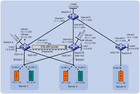
Analysis
To make sure the overlay network has connectivity,, configure a routing protocol on these switches to advertise routes for reaching their interfaces, including the loopback interfaces. In this example, OSPF is used.
To conserve resources, configure Switch C to reflect routes for Switch A, Switch B, and Switch D.
Software versions used
This configuration example was created and verified on S6890 CMW710-R2712.
Restrictions and guidelines
In a DR system, DR member devices must have the same EVPN configuration.
As a best practice, use the IP address of a loopback interface as the virtual VTEP address.
You can configure only the following criteria for Ethernet service instances on DR interfaces:
· encapsulation s-vid { vlan-id | vlan-id-list }
· encapsulation untagged
As a best practice, do not redistribute external routes on the DR member devices.
You must disable spanning tree on the Layer 2 traffic outgoing interface for the VXLAN tunnel that acts as the IPL.
By default, interfaces on S6890 switches are disabled (in ADM or Administratively Down state). To have an interface operate, you must use the undo shutdown command to enable that interface.
Procedures
Configuring Layer 3 interfaces
# Configure the Layer 3 interfaces on Switch A.
[SwitchA] interface loopback 0
[SwitchA-Loopback0] ip address 1.1.1.1 32
[SwitchA-Loopback0] quit
[SwitchA] interface loopback 1
[SwitchA-Loopback1] ip address 1.2.3.4 32
[SwitchA-Loopback1] quit
[SwitchA] vlan 11
[SwitchA-vlan11] port ten-gigabitethernet 1/0/5
[SwitchA-vlan11] quit
[SwitchA] interface vlan-interface 11
[SwitchA-Vlan-interface11] ip address 11.1.1.1 24
[SwitchA-Vlan-interface11] quit
# Configure the Layer 3 interfaces on other switches. (Details not shown.)
# On VM 1, VM 3, and VM 5, specify 10.1.1.1 as the gateway address. On VM 2 and VM 4, specify 10.1.2.1 as the gateway address. (Details not shown.)
Configuring OSPF
Configuring Switch A
# Configure OSPF to advertise the networks attached to the Layer 3 interfaces.
[SwitchA] ospf 1 router-id 1.1.1.1
[SwitchA-ospf-1] area 0
[SwitchA-ospf-1-area-0.0.0.0] network 1.1.1.1 0.0.0.0
[SwitchA-ospf-1-area-0.0.0.0] network 1.2.3.4 0.0.0.0
[SwitchA-ospf-1-area-0.0.0.0] network 11.1.1.0 0.0.0.255
[SwitchA-ospf-1-area-0.0.0.0] quit
[SwitchA-ospf-1] quit
Configuring Switch B
# Configure OSPF to advertise the networks attached to the Layer 3 interfaces.
[SwitchB] ospf 1 router-id 2.2.2.2
[SwitchB-ospf-1] area 0
[SwitchB-ospf-1-area-0.0.0.0] network 2.2.2.2 0.0.0.0
[SwitchB-ospf-1-area-0.0.0.0] network 1.2.3.4 0.0.0.0
[SwitchB-ospf-1-area-0.0.0.0] network 12.1.1.0 0.0.0.255
[SwitchB-ospf-1-area-0.0.0.0] quit
[SwitchB-ospf-1] quit
Configuring Switch C
# Configure OSPF to advertise the networks attached to the Layer 3 interfaces.
[SwitchC] ospf 1 router-id 3.3.3.3
[SwitchC-ospf-1] area 0
[SwitchC-ospf-1-area-0.0.0.0] network 3.3.3.3 0.0.0.0
[SwitchC-ospf-1-area-0.0.0.0] network 11.1.1.0 0.0.0.255
[SwitchC-ospf-1-area-0.0.0.0] network 12.1.1.0 0.0.0.255
[SwitchC-ospf-1-area-0.0.0.0] network 13.1.1.0 0.0.0.255
[SwitchC-ospf-1-area-0.0.0.0] quit
[SwitchC-ospf-1] quit
Configuring Switch D
# Configure OSPF to advertise the networks attached to the Layer 3 interfaces.
[SwitchD] ospf 1 router-id 4.4.4.4
[SwitchD-ospf-1] area 0
[SwitchD-ospf-1-area-0.0.0.0] network 4.4.4.4 0.0.0.0
[SwitchD-ospf-1-area-0.0.0.0] network 13.1.1.0 0.0.0.255
[SwitchD-ospf-1-area-0.0.0.0] quit
[SwitchD-ospf-1] quit
Configuring EVPN
Configuring Switch A
# Enable L2VPN.
[SwitchA] l2vpn enable
# Disable remote MAC address learning and remote ARP learning.
[SwitchA] vxlan tunnel mac-learning disable
[SwitchA] vxlan tunnel arp-learning disable
# Specify the reserved VXLAN as VXLAN 1234.
[SwitchA] reserved vxlan 1234
# Configure the EVPN global MAC address as 0002-0003-0004.
[SwitchA] evpn global-mac 2-3-4
# Create an EVPN instance on VSI vpna.
[SwitchA] vsi vpna
[SwitchA-vsi-vpna] evpn encapsulation vxlan
# Configure the switch to automatically generate an RD and a route target for the EVPN instance.
[SwitchA-vsi-vpna-evpn-vxlan] route-distinguisher auto
[SwitchA-vsi-vpna-evpn-vxlan] vpn-target auto
[SwitchA-vsi-vpna-evpn-vxlan] quit
# Create VXLAN 10.
[SwitchA-vsi-vpna] vxlan 10
[SwitchA-vsi-vpna-vxlan-10] quit
[SwitchA-vsi-vpna] quit
# Create an EVPN instance on VSI vpnb.
[SwitchA] vsi vpnb
[SwitchA-vsi-vpnb] evpn encapsulation vxlan
# Configure the switch to automatically generate an RD and a route target for the EVPN instance.
[SwitchA-vsi-vpnb-evpn-vxlan] route-distinguisher auto
[SwitchA-vsi-vpnb-evpn-vxlan] vpn-target auto
[SwitchA-vsi-vpnb-evpn-vxlan] quit
# Create VXLAN 20.
[SwitchA-vsi-vpnb] vxlan 20
[SwitchA-vsi-vpnb-vxlan-20] quit
[SwitchA-vsi-vpnb] quit
Configuring Switch B
# Enable L2VPN.
[SwitchB] l2vpn enable
# Disable remote MAC address learning and remote ARP learning.
[SwitchB] vxlan tunnel mac-learning disable
[SwitchB] vxlan tunnel arp-learning disable
# Specify the reserved VXLAN as VXLAN 1234.
[SwitchB] reserved vxlan 1234
# Configure the EVPN global MAC address as 0002-0003-0004.
[SwitchB] evpn global-mac 2-3-4
# Create an EVPN instance on VSI vpna.
[SwitchB] vsi vpna
[SwitchB-vsi-vpna] evpn encapsulation vxlan
# Configure the switch to automatically generate an RD and a route target for the EVPN instance.
[SwitchB-vsi-vpna-evpn-vxlan] route-distinguisher auto
[SwitchB-vsi-vpna-evpn-vxlan] vpn-target auto
[SwitchB-vsi-vpna-evpn-vxlan] quit
# Create VXLAN 10.
[SwitchB-vsi-vpna] vxlan 10
[SwitchB-vsi-vpna-vxlan-10] quit
[SwitchB-vsi-vpna] quit
# Create an EVPN instance on VSI vpnb.
[SwitchB] vsi vpnb
[SwitchB-vsi-vpnb] evpn encapsulation vxlan
# Configure the switch to automatically generate an RD and a route target for the EVPN instance.
[SwitchB-vsi-vpnb-evpn-vxlan] route-distinguisher auto
[SwitchB-vsi-vpnb-evpn-vxlan] vpn-target auto
[SwitchB-vsi-vpnb-evpn-vxlan] quit
# Create VXLAN 20.
[SwitchB-vsi-vpnb] vxlan 20
[SwitchB-vsi-vpnb-vxlan-20] quit
[SwitchB-vsi-vpnb] quit
Configuring Switch D
# Enable L2VPN.
[SwitchD] l2vpn enable
# Disable remote MAC address learning and remote ARP learning.
[SwitchD] vxlan tunnel mac-learning disable
[SwitchD] vxlan tunnel arp-learning disable
# Create an EVPN instance on VSI vpna.
[SwitchD] vsi vpna
[SwitchD-vsi-vpna] evpn encapsulation vxlan
# Configure the switch to automatically generate an RD and a route target for the EVPN instance.
[SwitchD-vsi-vpna-evpn-vxlan] route-distinguisher auto
[SwitchD-vsi-vpna-evpn-vxlan] vpn-target auto
[SwitchD-vsi-vpna-evpn-vxlan] quit
# Create VXLAN 10.
[SwitchD-vsi-vpna] vxlan 10
[SwitchD-vsi-vpna-vxlan-10] quit
[SwitchD-vsi-vpna] quit
Configuring distributed EVPN gateways
Configuring Switch A
# Configure RD and route target settings for VPN instance vpna.
[SwitchA] ip vpn-instance vpna
[SwitchA-vpn-instance-vpna] route-distinguisher 1:1
[SwitchA-vpn-instance-vpna] address-family ipv4
[SwitchA-vpn-ipv4-vpna] vpn-target 2:2
[SwitchA-vpn-ipv4-vpna] quit
[SwitchA-vpn-instance-vpna] address-family evpn
[SwitchA-vpn-evpn-vpna] vpn-target 1:1
[SwitchA-vpn-evpn-vpna] quit
[SwitchA-vpn-instance-vpna] quit
# Configure VSI-interface 1 as a distributed gateway.
[SwitchA] interface vsi-interface 1
[SwitchA-Vsi-interface1] ip binding vpn-instance vpna
[SwitchA-Vsi-interface1] ip address 10.1.1.1 255.255.255.0
[SwitchA-Vsi-interface1] mac-address 1-1-1
[SwitchA-Vsi-interface1] distributed-gateway local
[SwitchA-Vsi-interface1] local-proxy-arp enable
[SwitchA-Vsi-interface1] quit
# Configure VSI-interface 2 as a distributed gateway.
[SwitchA] interface vsi-interface 2
[SwitchA-Vsi-interface2] ip binding vpn-instance vpna
[SwitchA-Vsi-interface2] ip address 10.1.2.1 255.255.255.0
[SwitchA-Vsi-interface2] mac-address 2-2-2
[SwitchA-Vsi-interface2] distributed-gateway local
[SwitchA-Vsi-interface2] local-proxy-arp enable
[SwitchA-Vsi-interface2] quit
# Create VSI-interface 3. Associate VSI-interface 3 with VPN instance vpna, and configure the L3 VXLAN ID as 1000 for the VPN instance.
[SwitchA] interface vsi-interface 3
[SwitchA-Vsi-interface3] ip binding vpn-instance vpna
[SwitchA-Vsi-interface3] l3-vni 1000
[SwitchA-Vsi-interface3] quit
# Specify VSI-interface 1 as the gateway interface for VSI vpna.
[SwitchA] vsi vpna
[SwitchA-vsi-vpna] gateway vsi-interface 1
[SwitchA-vsi-vpna] quit
# Specify VSI-interface 2 as the gateway interface for VSI vpnb.
[SwitchA] vsi vpnb
[SwitchA-vsi-vpnb] gateway vsi-interface 2
[SwitchA-vsi-vpnb] quit
Configuring Switch B
# Configure RD and route target settings for VPN instance vpna.
[SwitchB] ip vpn-instance vpna
[SwitchB-vpn-instance-vpna] route-distinguisher 1:1
[SwitchB-vpn-instance-vpna] address-family ipv4
[SwitchB-vpn-ipv4-vpna] vpn-target 2:2
[SwitchB-vpn-ipv4-vpna] quit
[SwitchB-vpn-instance-vpna] address-family evpn
[SwitchB-vpn-evpn-vpna] vpn-target 1:1
[SwitchB-vpn-evpn-vpna] quit
[SwitchB-vpn-instance-vpna] quit
# Configure VSI-interface 1 as a distributed gateway.
[SwitchB] interface vsi-interface 1
[SwitchB-Vsi-interface1] ip binding vpn-instance vpna
[SwitchB-Vsi-interface1] ip address 10.1.1.1 255.255.255.0
[SwitchB-Vsi-interface1] mac-address 1-1-1
[SwitchB-Vsi-interface1] distributed-gateway local
[SwitchB-Vsi-interface1] local-proxy-arp enable
[SwitchB-Vsi-interface1] quit
# Configure VSI-interface 2 as a distributed gateway.
[SwitchB] interface vsi-interface 2
[SwitchB-Vsi-interface2] ip binding vpn-instance vpna
[SwitchB-Vsi-interface2] ip address 10.1.2.1 255.255.255.0
[SwitchB-Vsi-interface2] mac-address 2-2-2
[SwitchB-Vsi-interface2] distributed-gateway local
[SwitchB-Vsi-interface2] local-proxy-arp enable
[SwitchB-Vsi-interface2] quit
# Create VSI-interface 3. Associate VSI-interface 3 with VPN instance vpna, and configure the L3 VXLAN ID as 1000 for the VPN instance.
[SwitchB] interface vsi-interface 3
[SwitchB-Vsi-interface3] ip binding vpn-instance vpna
[SwitchB-Vsi-interface3] l3-vni 1000
[SwitchB-Vsi-interface3] quit
# Specify VSI-interface 1 as the gateway interface for VSI vpna.
[SwitchB] vsi vpna
[SwitchB-vsi-vpna] gateway vsi-interface 1
[SwitchB-vsi-vpna] quit
# Specify VSI-interface 2 as the gateway interface for VSI vpnb.
[SwitchB] vsi vpnb
[SwitchB-vsi-vpnb] gateway vsi-interface 2
[SwitchB-vsi-vpnb] quit
Configuring Switch D
# Configure RD and route target settings for VPN instance vpna.
[SwitchD] ip vpn-instance vpna
[SwitchD-vpn-instance-vpna] route-distinguisher 1:1
[SwitchD-vpn-instance-vpna] address-family ipv4
[SwitchD-vpn-ipv4-vpna] vpn-target 2:2
[SwitchD-vpn-ipv4-vpna] quit
[SwitchD-vpn-instance-vpna] address-family evpn
[SwitchD-vpn-evpn-vpna] vpn-target 1:1
[SwitchD-vpn-evpn-vpna] quit
[SwitchD-vpn-instance-vpna] quit
# Configure VSI-interface 1 as a distributed gateway.
[SwitchD] interface vsi-interface 1
[SwitchD-Vsi-interface1] ip binding vpn-instance vpna
[SwitchD-Vsi-interface1] ip address 10.1.1.1 255.255.255.0
[SwitchD-Vsi-interface1] mac-address 1-1-1
[SwitchD-Vsi-interface1] distributed-gateway local
[SwitchD-Vsi-interface1] local-proxy-arp enable
[SwitchD-Vsi-interface1] quit
# Create VSI-interface 3. Associate VSI-interface 3 with VPN instance vpna, and configure the L3 VXLAN ID as 1000 for the VPN instance.
[SwitchD] interface vsi-interface 3
[SwitchD-Vsi-interface3] ip binding vpn-instance vpna
[SwitchD-Vsi-interface3] l3-vni 1000
[SwitchD-Vsi-interface3] quit
# Specify VSI-interface 1 as the gateway interface for VSI vpna.
[SwitchD] vsi vpna
[SwitchD-vsi-vpna] gateway vsi-interface 1
[SwitchD-vsi-vpna] quit
Configuring DRNI
Configuring Switch A
# Specify the virtual VTEP address as 1.2.3.4.
[SwitchA] evpn drni group 1.2.3.4
# Configure DR system parameters.
[SwitchA] drni system-mac 0001-0002-0003
[SwitchA] drni system-number 1
[SwitchA] drni system-priority 10
[SwitchA] drni restore-delay 180
[SwitchA] drni keepalive ip destination 12.1.1.2 source 11.1.1.1
# Create a tunnel to Switch B, specify the tunnel interface as the IPP, and set the ToS of tunneled packets to 100.
[SwitchA] interface tunnel 1 mode vxlan
[SwitchA-Tunnel1] source 1.1.1.1
[SwitchA-Tunnel1] destination 2.2.2.2
[SwitchA-Tunnel1] port drni intra-portal-port 1
[SwitchA-Tunnel1] tunnel tos 100
[SwitchA-Tunnel1] quit
# Disable the static source check feature on Ten-GigabitEthernet 1/0/5.
[SwitchA] interface ten-gigabitethernet 1/0/5
[SwitchA-Ten-GigabitEthernet1/0/5] undo mac-address static source-check enable
[SwitchA-Ten-GigabitEthernet1/0/5] quit
# Create Layer 2 dynamic aggregate interface Bridge-Aggregation 4.
[SwitchA] interface bridge-aggregation 4
[SwitchA-Bridge-Aggregation4] link-aggregation mode dynamic
[SwitchA-Bridge-Aggregation4] quit
# Assign Ten-GigabitEthernet 1/0/1 to aggregation group 4.
[SwitchA] interface ten-gigabitethernet 1/0/1
[SwitchA-Ten-GigabitEthernet1/0/1] port link-aggregation group 4
[SwitchA-Ten-GigabitEthernet1/0/1] quit
# Assign Bridge-Aggregation 4 to DR group 4.
[SwitchA] interface bridge-aggregation 4
[SwitchA-Bridge-Aggregation4] port drni group 4
[SwitchA-Bridge-Aggregation4] quit
# Create Layer 2 dynamic aggregate interface Bridge-Aggregation 5.
[SwitchA] interface bridge-aggregation 5
[SwitchA-Bridge-Aggregation5] link-aggregation mode dynamic
[SwitchA-Bridge-Aggregation5] quit
# Assign Ten-GigabitEthernet 1/0/2 to aggregation group 5.
[SwitchA] interface ten-gigabitethernet 1/0/2
[SwitchA-Ten-GigabitEthernet1/0/2] port link-aggregation group 5
[SwitchA-Ten-GigabitEthernet1/0/2] quit
# Assign Bridge-Aggregation 5 to DR group 5.
[SwitchA] interface bridge-aggregation 5
[SwitchA-Bridge-Aggregation5] port drni group 5
[SwitchA-Bridge-Aggregation5] quit
# Exclude all interfaces used by EVPN from the shutdown action by DRNI MAD.
[SwitchA] mad exclude interface tunnel 1
[SwitchA] mad exclude interface loopback0
[SwitchA] mad exclude interface ten-gigabitethernet1/0/5
[SwitchA] mad exclude interface vsi-interface 1
[SwitchA] mad exclude interface vsi-interface 2
[SwitchA] mad exclude interface vlan-interface 11
Configuring Switch B
# Specify the virtual VTEP address as 1.2.3.4.
[SwitchB] evpn drni group 1.2.3.4
# Configure DR system parameters.
[SwitchB] drni system-mac 0001-0002-0003
[SwitchB] drni system-number 2
[SwitchB] drni system-priority 10
[SwitchB] drni restore-delay 180
[SwitchB] drni keepalive ip destination 11.1.1.1 source 12.1.1.2
# Create a tunnel to Switch A, specify the tunnel interface as the IPP, and set the ToS of tunneled packets to 100.
[SwitchB] interface tunnel 1 mode vxlan
[SwitchB-Tunnel1] source 2.2.2.2
[SwitchB-Tunnel1] destination 1.1.1.1
[SwitchB-Tunnel1] port drni intra-portal-port 1
[SwitchB-Tunnel1] tunnel tos 100
[SwitchB-Tunnel1] quit
# Disable the static source check feature on Ten-GigabitEthernet 1/0/5.
[SwitchB] interface ten-gigabitethernet 1/0/5
[SwitchB-Ten-GigabitEthernet1/0/5] undo mac-address static source-check enable
[SwitchB-Ten-GigabitEthernet1/0/5] quit
# Create Layer 2 dynamic aggregate interface Bridge-Aggregation 4.
[SwitchB] interface bridge-aggregation 4
[SwitchB-Bridge-Aggregation4] link-aggregation mode dynamic
[SwitchB-Bridge-Aggregation4] quit
# Assign Ten-GigabitEthernet 1/0/1 to aggregation group 4.
[SwitchB] interface ten-gigabitethernet 1/0/1
[SwitchB-Ten-GigabitEthernet1/0/1] port link-aggregation group 4
[SwitchB-Ten-GigabitEthernet1/0/1] quit
# Assign Bridge-Aggregation 4 to DR group 4.
[SwitchB] interface bridge-aggregation 4
[SwitchB-Bridge-Aggregation4] port drni group 4
[SwitchB-Bridge-Aggregation4] quit
# Create Layer 2 dynamic aggregate interface Bridge-Aggregation 5.
[SwitchB] interface bridge-aggregation 5
[SwitchB-Bridge-Aggregation5] link-aggregation mode dynamic
[SwitchB-Bridge-Aggregation5] quit
# Assign Ten-GigabitEthernet 1/0/2 to aggregation group 5.
[SwitchB] interface ten-gigabitethernet 1/0/2
[SwitchB-Ten-GigabitEthernet1/0/2] port link-aggregation group 5
[SwitchB-Ten-GigabitEthernet1/0/2] quit
# Assign Bridge-Aggregation 5 to DR group 5.
[SwitchB] interface bridge-aggregation 5
[SwitchB-Bridge-Aggregation5] port drni group 5
[SwitchB-Bridge-Aggregation5] quit
# Exclude all interfaces used by EVPN from the shutdown action by DRNI MAD.
[SwitchB] mad exclude interface tunnel 1
[SwitchB] mad exclude interface loopback0
[SwitchB] mad exclude interface ten-gigabitethernet1/0/5
[SwitchB] mad exclude interface vsi-interface 1
[SwitchB] mad exclude interface vsi-interface 2
[SwitchB] mad exclude interface vlan-interface 12
Configuring BGP to advertise BGP EVPN routes
Configuring Switch A
# Configure BGP to advertise BGP EVPN routes.
[SwitchA] bgp 200
[SwitchA-bgp-default] peer 3.3.3.3 as-number 200
[SwitchA-bgp-default] peer 3.3.3.3 connect-interface loopback 0
[SwitchA-bgp-default] address-family l2vpn evpn
[SwitchA-bgp-default-evpn] peer 3.3.3.3 enable
[SwitchA-bgp-default-evpn] quit
[SwitchA-bgp-default] quit
Configuring Switch B
# Configure BGP to advertise BGP EVPN routes.
[SwitchB] bgp 200
[SwitchB-bgp-default] peer 3.3.3.3 as-number 200
[SwitchB-bgp-default] peer 3.3.3.3 connect-interface loopback 0
[SwitchB-bgp-default] address-family l2vpn evpn
[SwitchB-bgp-default-evpn] peer 3.3.3.3 enable
[SwitchB-bgp-default-evpn] quit
[SwitchB-bgp-default] quit
Configuring Switch C
# Configure BGP to advertise BGP EVPN routes and configure the switch as an RR.
[SwitchC] bgp 200
[SwitchC-bgp-default] group evpn
[SwitchC-bgp-default] peer 1.1.1.1 group evpn
[SwitchC-bgp-default] peer 2.2.2.2 group evpn
[SwitchC-bgp-default] peer 4.4.4.4 group evpn
[SwitchC-bgp-default] peer evpn as-number 200
[SwitchC-bgp-default] peer evpn connect-interface loopback 0
[SwitchC-bgp-default] address-family l2vpn evpn
[SwitchC-bgp-default-evpn] peer evpn enable
[SwitchC-bgp-default-evpn] undo policy vpn-target
[SwitchC-bgp-default-evpn] peer evpn reflect-client
[SwitchC-bgp-default-evpn] quit
[SwitchC-bgp-default] quit
Configuring Switch D
# Configure BGP to advertise BGP EVPN routes.
[SwitchD] bgp 200
[SwitchD-bgp-default] peer 3.3.3.3 as-number 200
[SwitchD-bgp-default] peer 3.3.3.3 connect-interface loopback 0
[SwitchD-bgp-default] address-family l2vpn evpn
[SwitchD-bgp-default-evpn] peer 3.3.3.3 enable
[SwitchD-bgp-default-evpn] quit
[SwitchD-bgp-default] quit
Mapping Ethernet service instances to VSIs
Configuring Switch A
# On Bridge-Aggregation 4, create Ethernet service instance 1000 to match VLAN 2.
[SwitchA] interface bridge-aggregation 4
[SwitchA-Bridge-Aggregation4] service-instance 1000
[SwitchA-Bridge-Aggregation4-srv1000] encapsulation s-vid 2
# Map Ethernet service instance 1000 to VSI vpna.
[SwitchA-Bridge-Aggregation4-srv1000] xconnect vsi vpna
[SwitchA-Bridge-Aggregation4-srv1000] quit
# On Bridge-Aggregation 5, create Ethernet service instance 1000 to match VLAN 3.
[SwitchA] interface bridge-aggregation 5
[SwitchA-Bridge-Aggregation5] service-instance 1000
[SwitchA-Bridge-Aggregation5-srv1000] encapsulation s-vid 3
# Map Ethernet service instance 1000 to VSI vpnb.
[SwitchA-Bridge-Aggregation5-srv1000] xconnect vsi vpnb
[SwitchA-Bridge-Aggregation5-srv1000] quit
Configuring Switch B
# On Bridge-Aggregation 4, create Ethernet service instance 1000 to match VLAN 2.
[SwitchB] interface bridge-aggregation 4
[SwitchB-Bridge-Aggregation4] service-instance 1000
[SwitchB-Bridge-Aggregation4-srv1000] encapsulation s-vid 2
# Map Ethernet service instance 1000 to VSI vpna.
[SwitchB-Bridge-Aggregation4-srv1000] xconnect vsi vpna
[SwitchB-Bridge-Aggregation4-srv1000] quit
# On Bridge-Aggregation 5, create Ethernet service instance 1000 to match VLAN 3.
[SwitchB] interface bridge-aggregation 5
[SwitchB-Bridge-Aggregation5] service-instance 1000
[SwitchB-Bridge-Aggregation5-srv1000] encapsulation s-vid 3
# Map Ethernet service instance 1000 to VSI vpnb.
[SwitchB-Bridge-Aggregation5-srv1000] xconnect vsi vpnb
[SwitchB-Bridge-Aggregation5-srv1000] quit
Configuring Switch D
# On Ten-GigabitEthernet 1/0/1, create Ethernet service instance 1000 to match VLAN 2.
[SwitchD] interface ten-gigabitethernet 1/0/1
[SwitchD-Ten-GigabitEthernet1/0/1] service-instance 1000
[SwitchD-Ten-GigabitEthernet1/0/1-srv1000] encapsulation s-vid 2
# Map Ethernet service instance 1000 to VSI vpna.
[SwitchD-Ten-GigabitEthernet1/0/1-srv1000] xconnect vsi vpna
[SwitchD-Ten-GigabitEthernet1/0/1-srv1000] quit
Verifying the configuration
Verifying the configuration on a DR member device
The verification procedure uses Switch A as an example.
# Verify that Switch A has BGP EVPN routes.
[Switch A]display bgp l2vpn evpn
BGP local router ID is 1.2.3.4
Status codes: * - valid, > - best, d - dampened, h - history
s - suppressed, S - stale, i - internal, e - external
a - additional-path
Origin: i - IGP, e - EGP, ? - incomplete
Total number of routes from all PEs: 3
Route distinguisher: 1:1(vpna)
Total number of routes: 2
Network NextHop MED LocPrf PrefVal Path/Ogn
* > [5][0][24][10.1.1.0]/80
1.1.1.1 0 100 32768 i
* > [5][0][24][10.1.2.0]/80
1.1.1.1 0 100 32768 i
Route distinguisher: 1:10
Total number of routes: 4
Network NextHop MED LocPrf PrefVal Path/Ogn
* > [3][0][32][1.1.1.1]/80
1.1.1.1 0 100 32768 i
* > [3][0][32][1.2.3.4]/80
1.2.3.4 0 100 32768 i
* >i [3][0][32][2.2.2.2]/80
2.2.2.2 0 100 0 i
* >i [3][0][32][4.4.4.4]/80
4.4.4.4 0 100 0 i
Route distinguisher: 1:20
Total number of routes: 3
Network NextHop MED LocPrf PrefVal Path/Ogn
* > [3][0][32][1.1.1.1]/80
1.1.1.1 0 100 32768 i
* > [3][0][32][1.2.3.4]/80
1.2.3.4 0 100 32768 i
* >i [3][0][32][2.2.2.2]/80
2.2.2.2 0 100 0 i
# Verify that the IPL Tunnel 1 is up, and Tunnel 0 to Switch D uses the virtual VTEP address as the source address.
[SwitchA] display interface tunnel
Tunnel0
Current state: UP
Line protocol state: UP
Description: Tunnel0 Interface
Bandwidth: 64 kbps
Maximum transmission unit: 1464
Internet protocol processing: Disabled
Last clearing of counters: Never
Tunnel source 1.2.3.4, destination 4.4.4.4
Tunnel protocol/transport UDP_VXLAN/IP
Last 300 seconds input rate: 0 bytes/sec, 0 bits/sec, 0 packets/sec
Last 300 seconds output rate: 0 bytes/sec, 0 bits/sec, 0 packets/sec
Input: 0 packets, 0 bytes, 0 drops
Output: 0 packets, 0 bytes, 0 drops
Tunnel1
Current state: UP
Line protocol state: UP
Description: Tunnel1 Interface
Bandwidth: 64 kbps
Maximum transmission unit: 1464
Internet protocol processing: Disabled
Last clearing of counters: Never
Tunnel source 1.1.1.1, destination 2.2.2.2
Tunnel protocol/transport UDP_VXLAN/IP
Last 300 seconds input rate: 149 bytes/sec, 1192 bits/sec, 1 packets/sec
Last 300 seconds output rate: 379 bytes/sec, 3032 bits/sec, 3 packets/sec
Input: 398 packets, 46446 bytes, 0 drops
Output: 3597 packets, 363591 bytes, 0 drops
# Verify that the VXLAN tunnels have been assigned to VXLAN 10 and VXLAN 20.
[SwitchA] display l2vpn vsi verbose
VSI Name: Auto_L3VNI1000_3
VSI Index : 1
VSI State : Down
MTU : 1500
Bandwidth : Unlimited
Broadcast Restrain : Unlimited
Multicast Restrain : Unlimited
Unknown Unicast Restrain: Unlimited
MAC Learning : Enabled
MAC Table Limit : -
MAC Learning rate : -
Drop Unknown : -
Flooding : Enabled
Statistics : Disabled
Gateway Interface : VSI-interface 3
VXLAN ID : 1000
VSI Name: vpna
VSI Index : 0
VSI State : Up
MTU : 1500
Bandwidth : Unlimited
Broadcast Restrain : Unlimited
Multicast Restrain : Unlimited
Unknown Unicast Restrain: Unlimited
MAC Learning : Enabled
MAC Table Limit : -
MAC Learning rate : -
Drop Unknown : -
Flooding : Enabled
Statistics : Disabled
Gateway Interface : VSI-interface 1
VXLAN ID : 10
Tunnels:
Tunnel Name Link ID State Type Flood proxy
Tunnel0 0x5000000 UP Auto Disabled
Tunnel1 0x5000001 UP Manual Disabled
ACs:
AC Link ID State Type
BAGG4 srv1000 0 Up Manual
VSI Name: vpnb
VSI Index : 2
VSI State : Up
MTU : 1500
Bandwidth : Unlimited
Broadcast Restrain : Unlimited
Multicast Restrain : Unlimited
Unknown Unicast Restrain: Unlimited
MAC Learning : Enabled
MAC Table Limit : -
MAC Learning rate : -
Drop Unknown : -
Flooding : Enabled
Statistics : Disabled
Gateway Interface : VSI-interface 2
VXLAN ID : 20
Tunnels:
Tunnel Name Link ID State Type Flood proxy
Tunnel1 0x5000001 UP Manual Disabled
ACs:
AC Link ID State Type
BAGG5 srv1000 0 Up Manual
Verifying the network connectivity of the VMs
# Verify that the VMs can communicate when both Switch A and Switch B are operating correctly. (Details not shown.)
# Verify that VM 1 and VM 5 can communicate when Switch A's or Switch B's links to the local site are disconnected. (Details not shown.)
Configuration files
· Switch A:
#
ip vpn-instance vpna
route-distinguisher 1:1
#
address-family ipv4
vpn-target 2:2 import-extcommunity
vpn-target 2:2 export-extcommunity
#
address-family evpn
vpn-target 1:1 import-extcommunity
vpn-target 1:1 export-extcommunity
#
vxlan tunnel mac-learning disable
#
ospf 1 router-id 1.1.1.1
area 0.0.0.0
network 1.1.1.1 0.0.0.0
network 1.2.3.4 0.0.0.0
network 11.1.1.0 0.0.0.255
#
vlan 11
#
l2vpn enable
reserved vxlan 1234
vxlan tunnel arp-learning disable
evpn drni group 1.2.3.4
evpn global-mac 0002-0003-0004
#
vsi vpna
gateway vsi-interface 1
vxlan 10
evpn encapsulation vxlan
route-distinguisher auto
vpn-target auto export-extcommunity
vpn-target auto import-extcommunity
#
vsi vpnb
gateway vsi-interface 2
vxlan 20
evpn encapsulation vxlan
route-distinguisher auto
vpn-target auto export-extcommunity
vpn-target auto import-extcommunity
#
interface Bridge-Aggregation4
link-aggregation mode dynamic
port drni group 4
#
service-instance 1000
encapsulation s-vid 2
xconnect vsi vpna
#
interface Bridge-Aggregation5
link-aggregation mode dynamic
port drni group 5
#
service-instance 1000
encapsulation s-vid 3
xconnect vsi vpnb
#
interface LoopBack0
ip address 1.1.1.1 255.255.255.255
#
interface LoopBack1
ip address 1.2.3.4 255.255.255.255
#
interface Vlan-interface11
ip address 11.1.1.1 255.255.255.0
#
interface Ten-GigabitEthernet1/0/1
port link-mode bridge
port link-aggregation group 4
#
interface Ten-GigabitEthernet1/0/2
port link-mode bridge
port link-aggregation group 5
#
interface Ten-GigabitEthernet1/0/5
port link-mode bridge
port access vlan 11
undo mac-address static source-check enable
#
interface Vsi-interface1
ip binding vpn-instance vpna
ip address 10.1.1.1 255.255.255.0
mac-address 0001-0001-0001
local-proxy-arp enable
distributed-gateway local
#
interface Vsi-interface2
ip binding vpn-instance vpna
ip address 10.1.2.1 255.255.255.0
mac-address 0002-0002-0002
local-proxy-arp enable
distributed-gateway local
#
interface Vsi-interface3
ip binding vpn-instance vpna
l3-vni 1000
#
interface Tunnel1 mode vxlan
port drni intra-portal-port 1
source 1.1.1.1
destination 2.2.2.2
tunnel tos 100
#
bgp 200
peer 3.3.3.3 as-number 200
peer 3.3.3.3 connect-interface LoopBack0
#
address-family l2vpn evpn
peer 3.3.3.3 enable
#
drni keepalive ip destination 12.1.1.2 source 11.1.1.1
drni restore-delay 180
drni system-mac 0001-0001-0001
drni system-number 1
drni system-priority 10
#
mad exclude interface LoopBack0
mad exclude interface Ten-GigabitEthernet1/0/5
mad exclude interface Tunnel1
mad exclude interface Vlan-interface 11
mad exclude interface Vsi-interface1
mad exclude interface Vsi-interface2
#
return
· Switch B:
#
ip vpn-instance vpna
route-distinguisher 1:1
#
address-family ipv4
vpn-target 2:2 import-extcommunity
vpn-target 2:2 export-extcommunity
#
address-family evpn
vpn-target 1:1 import-extcommunity
vpn-target 1:1 export-extcommunity
#
vxlan tunnel mac-learning disable
#
ospf 1 router-id 2.2.2.2
area 0.0.0.0
network 1.2.3.4 0.0.0.0
network 2.2.2.2 0.0.0.0
network 12.1.1.0 0.0.0.255
#
vlan 12
#
l2vpn enable
reserved vxlan 1234
vxlan tunnel arp-learning disable
evpn drni group 1.2.3.4
evpn global-mac 0002-0003-0004
#
vsi vpna
gateway vsi-interface 1
vxlan 10
evpn encapsulation vxlan
route-distinguisher auto
vpn-target auto export-extcommunity
vpn-target auto import-extcommunity
#
vsi vpnb
gateway vsi-interface 2
vxlan 20
evpn encapsulation vxlan
route-distinguisher auto
vpn-target auto export-extcommunity
vpn-target auto import-extcommunity
#
interface Bridge-Aggregation4
link-aggregation mode dynamic
port drni group 4
#
service-instance 1000
encapsulation s-vid 2
xconnect vsi vpna
#
interface Bridge-Aggregation5
link-aggregation mode dynamic
port drni group 5
#
service-instance 1000
encapsulation s-vid 3
xconnect vsi vpnb
#
interface LoopBack0
ip address 2.2.2.2 255.255.255.255
#
interface LoopBack1
ip address 1.2.3.4 255.255.255.255
#
interface Vlan-interface12
ip address 12.1.1.2 255.255.255.0
#
interface Ten-GigabitEthernet1/0/1
port link-mode bridge
port link-aggregation group 4
#
interface Ten-GigabitEthernet1/0/2
port link-mode bridge
port link-aggregation group 5
#
interface Ten-GigabitEthernet1/0/5
port link-mode bridge
port access vlan 12
undo mac-address static source-check enable
#
interface Vsi-interface1
ip binding vpn-instance vpna
ip address 10.1.1.1 255.255.255.0
mac-address 0001-0001-0001
local-proxy-arp enable
distributed-gateway local
#
interface Vsi-interface2
ip binding vpn-instance vpna
ip address 10.1.2.1 255.255.255.0
mac-address 0002-0002-0002
local-proxy-arp enable
distributed-gateway local
#
interface Vsi-interface3
ip binding vpn-instance vpna
l3-vni 1000
#
interface Tunnel1 mode vxlan
port drni intra-portal-port 1
source 2.2.2.2
destination 1.1.1.1
tunnel tos 100
#
bgp 200
peer 3.3.3.3 as-number 200
peer 3.3.3.3 connect-interface LoopBack0
#
address-family l2vpn evpn
peer 3.3.3.3 enable
#
drni keepalive ip destination 11.1.1.1 source 12.1.1.2
drni restore-delay 180
drni system-mac 0001-0002-0003
drni system-number 2
drni system-priority 10
#
mad exclude interface LoopBack0
mad exclude interface Ten-GigabitEthernet1/0/5
mad exclude interface Tunnel1
mad exclude interface Vlan-interface 12
mad exclude interface Vsi-interface1
mad exclude interface Vsi-interface2
#
return
· Switch C:
#
ospf 1 router-id 3.3.3.3
area 0.0.0.0
network 3.3.3.3 0.0.0.0
network 11.1.1.0 0.0.0.255
network 12.1.1.0 0.0.0.255
network 13.1.1.0 0.0.0.255
#
vlan 11 to 13
#
interface LoopBack0
ip address 3.3.3.3 255.255.255.255
#
interface Vlan-interface11
ip address 11.1.1.3 255.255.255.0
#
interface Vlan-interface12
ip address 12.1.1.3 255.255.255.0
#
interface Vlan-interface13
ip address 13.1.1.3 255.255.255.0
#
interface Ten-GigabitEthernet1/0/1
port link-mode bridge
port access vlan 11
#
interface Ten-GigabitEthernet1/0/2
port link-mode bridge
port access vlan 12
#
interface Ten-GigabitEthernet1/0/3
port link-mode bridge
port access vlan 13
#
bgp 200
group evpn internal
peer evpn connect-interface LoopBack0
peer 1.1.1.1 group evpn
peer 2.2.2.2 group evpn
peer 4.4.4.4 group evpn
#
address-family l2vpn evpn
undo policy vpn-target
peer evpn enable
peer evpn reflect-client
#
return
· Switch D:
#
ip vpn-instance vpna
route-distinguisher 1:1
#
address-family ipv4
vpn-target 2:2 import-extcommunity
vpn-target 2:2 export-extcommunity
#
address-family evpn
vpn-target 1:1 import-extcommunity
vpn-target 1:1 export-extcommunity
#
vxlan tunnel mac-learning disable
#
ospf 1 router-id 4.4.4.4
area 0.0.0.0
network 4.4.4.4 0.0.0.0
network 13.1.1.0 0.0.0.255
#
vlan 13
#
l2vpn enable
vxlan tunnel arp-learning disable
#
vsi vpna
gateway vsi-interface 1
vxlan 10
evpn encapsulation vxlan
route-distinguisher auto
vpn-target auto export-extcommunity
vpn-target auto import-extcommunity
#
interface LoopBack0
ip address 4.4.4.4 255.255.255.255
#
interface Vlan-interface13
ip address 13.1.1.4 255.255.255.0
#
interface Ten-GigabitEthernet1/0/1
port link-mode bridge
#
service-instance 1000
encapsulation s-vid 2
xconnect vsi vpna
#
interface Ten-GigabitEthernet1/0/2
port link-mode bridge
port access vlan 13
#
interface Vsi-interface1
ip binding vpn-instance vpna
ip address 10.1.1.1 255.255.255.0
mac-address 0001-0001-0001
local-proxy-arp enable
distributed-gateway local
#
interface Vsi-interface3
ip binding vpn-instance vpna
l3-vni 1000
#
bgp 200
peer 3.3.3.3 as-number 200
peer 3.3.3.3 connect-interface LoopBack0
#
address-family l2vpn evpn
peer 3.3.3.3 enable
#
return
Related documentation
· H3C S6890 Switch Series EVPN Command Reference (R27xx)
· H3C S6890 Switch Series EVPN Configuration Guide (R27xx)
· H3C S6890 Switch Series Layer 2—LAN Switching Command Reference (R27xx)
· H3C S6890 Switch Series Layer 2—LAN Switching Configuration Guide (R27xx)