- Table of Contents
-
- H3C S6890 Switch Series Configuration Examples-Release 27xx-6W100
- 01-Login Management Configuration Examples
- 02-RBAC Configuration Examples
- 03-Software Upgrade Examples
- 04-ISSU Configuration Examples
- 05-Software Patching Examples
- 06-Ethernet Link Aggregation Configuration Examples
- 07-Port Isolation Configuration Examples
- 08-Spanning Tree Configuration Examples
- 09-VLAN Configuration Examples
- 10-VLAN Tagging Configuration Examples
- 11-DHCP Snooping Configuration Examples
- 12-Cross-Subnet Dynamic IP Address Allocation Configuration Examples
- 13-GRE Tunnel Configuration Examples
- 14-GRE with OSPF Configuration Examples
- 15-OSPF Configuration Examples
- 16-IS-IS Configuration Examples
- 17-BGP Configuration Examples
- 18-Policy-Based Routing Configuration Examples
- 19-OSPFv3 Configuration Examples
- 20-IPv6 IS-IS Configuration Examples
- 21-Routing Policy Configuration Examples
- 22-IGMP Snooping Configuration Examples
- 23-IGMP Configuration Examples
- 24-Multicast VPN Configuration Examples
- 25-Basic MPLS Configuration Examples
- 26-MPLS L3VPN Configuration Examples
- 27-ACL Configuration Examples
- 28-Control Plane-Based QoS Policy Configuration Examples
- 29-Traffic Policing Configuration Examples
- 30-GTS and Rate Limiting Configuration Examples
- 31-Priority Mapping and Queue Scheduling Configuration Examples
- 32-Traffic Filtering Configuration Examples
- 33-AAA Configuration Examples
- 34-SSH Configuration Examples
- 35-IP Source Guard Configuration Examples
- 36-Ethernet OAM Configuration Examples
- 37-CFD Configuration Examples
- 38-DLDP Configuration Examples
- 39-VRRP Configuration Examples
- 40-BFD Configuration Examples
- 41-NTP Configuration Examples
- 42-SNMP Configuration Examples
- 43-NQA Configuration Examples
- 44-Mirroring Configuration Examples
- 45-sFlow Configuration Examples
- 46-FCoE Configuration Examples
- 47-OpenFlow Configuration Examples
- 48-MAC Address Table Configuration Examples
- 49-Static Multicast MAC Address Entry Configuration Examples
- 50-IP Unnumbered Configuration Examples
- 51-MVRP Configuration Examples
- 52-MCE Configuration Examples
- 53-Congestion Avoidance and Queue Scheduling Configuration Examples
- 54-Attack Protection Configuration Examples
- 55-Smart Link Configuration Examples
- 56-RRPP Configuration Examples
- 57-BGP Route Selection Configuration Examples
- 58-IS-IS Route Summarization Configuration Examples
- 59-IRF Configuration Examples
- 60-MPLS OAM Configuration Examples
- 61-MPLS TE Configuration Examples
- 62-VXLAN Configuration Examples
- 63-DRNI Configuration Examples
- 64-DRNI and EVPN Configuration Examples
- 65-VCF Fabric Configuration Examples
- Related Documents
-
| Title | Size | Download |
|---|---|---|
| 20-IPv6 IS-IS Configuration Examples | 93.95 KB |
|
|
|
H3C S6890 Switch Series |
|
IPv6 IS-IS Configuration Examples |
|
|
Document version: 6W100-20190628
Copyright © 2019 New H3C Technologies Co., Ltd. All rights reserved.
No part of this manual may be reproduced or transmitted in any form or by any means without prior written consent of New H3C Technologies Co., Ltd.
Except for the trademarks of New H3C Technologies Co., Ltd., any trademarks that may be mentioned in this document are the property of their respective owners.
The information in this document is subject to change without notice.
Introduction
This document provides IPv6 IS-IS configuration examples.
Prerequisites
The configuration examples in this document were created and verified in a lab environment, and all the devices were started with the factory default configuration. When you are working on a live network, make sure you understand the potential impact of every command on your network.
This document assumes that you have basic knowledge of IPv6 IS-IS.
Example: Configuring IPv6 IS-IS
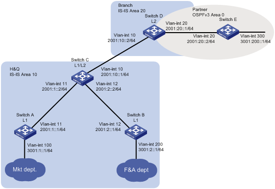
Network configuration
As shown in Figure 1, the company's headquarters and the branch run IPv6 IS-IS. The partner runs OSPFv3.
Configure the switches to meet the following requirements:
· The Marketing department can reach the Finance department, the branch, and the partner.
· The Finance department and the branch cannot reach each other, and the branch does not have a route to the Finance department.
Analysis
To meet the network requirements, you must perform the following tasks:
· Configure Switch A and Switch B in Area 10 as Level-1 routers to allow communication between the Marketing department and the Finance department.
· Configure route redistribution between IPv6 IS-IS and OSPFv3 on Switch D to allow communication between the Marketing department and the partner.
· Configure Switch C to use a prefix list to advertise only network 3001:1::/64 to Level-2. So that the branch does not have a route to the Finance department.
Software versions used
This configuration example was created and verified on S6890-CMW710-R2712.
Restrictions and guidelines
By default, interfaces on the device are disabled (in ADM or Administratively Down state). To have an interface operate, you must use the undo shutdown command to enable that interface.
Procedures
Configuring Switch A
# Configure an IPv6 address for VLAN-interface 11.
<SwitchA> system-view
[SwitchA] interface vlan-interface 11
[SwitchA-Vlan-interface11] ipv6 address 2001:1::1 64
[SwitchA-Vlan-interface11] quit
# Configure IPv6 addresses for other interfaces, as shown in Figure 1. (Details not shown.)
# Configure IPv6 IS-IS.
[SwitchA] isis 1
[SwitchA-isis-1] is-level level-1
[SwitchA-isis-1] network-entity 10.3001.0001.0001.00
[SwitchA-isis-1] address-family ipv6
[SwitchA-isis-1-ipv6] quit
[SwitchA-isis-1] quit
[SwitchA] interface vlan-interface 11
[SwitchA–vlan-interface 11] isis ipv6 enable 1
[SwitchA–vlan-interface 11] quit
[SwitchA] interface vlan-interface 100
[SwitchA–Vlan-interface100] isis ipv6 enable 1
[SwitchA–Vlan-interface100] quit
Configuring Switch B
# Configure an IPv6 address for VLAN-interface 12.
<SwitchB> system-view
[SwitchB] interface vlan-interface 12
[SwitchB-Vlan-interface12] ipv6 address 2001:2::1 64
[SwitchB-Vlan-interface12] quit
# Configure IPv6 addresses for other interfaces, as shown in Figure 1. (Details not shown.)
# Configure IPv6 IS-IS.
[SwitchB] isis 1
[SwitchB-isis-1] is-level level-1
[SwitchB-isis-1] network-entity 10.3001.0002.0001.00
[SwitchB-isis-1] address-family ipv6
[SwitchB-isis-1-ipv6] quit
[SwitchB-isis-1] quit
[SwitchB] interface vlan-interface 12
[SwitchB–Vlan-interface12] isis ipv6 enable 1
[SwitchB–Vlan-interface12] quit
[SwitchB] interface vlan-interface 200
[SwitchB–Vlan-interface 200] isis ipv6 enable 1
[SwitchB–Vlan-interface 200] quit
Configuring Switch C
# Configure an IPv6 address for VLAN-interface 11.
<SwitchC> system-view
[SwitchC] interface vlan-interface 11
[SwitchC-Vlan-interface11] ipv6 address 2001:1::2 64
[SwitchC-Vlan-interface11] quit
# Configure IPv6 addresses for other interfaces, as shown in Figure 1. (Details not shown.)
# Configure IPv6 IS-IS.
[SwitchC] isis 1
[SwitchC-isis-1] is-level level-1
[SwitchC-isis-1] network-entity 10.2001.0010.0001.00
[SwitchC-isis-1] address-family ipv6
[SwitchC-isis-1-ipv6] quit
[SwitchC-isis-1] quit
[SwitchC] interface vlan-interface 10
[SwitchC–Vlan-interface10] isis ipv6 enable 1
[SwitchC–Vlan-interface10] quit
[SwitchC] interface vlan-interface 11
[SwitchC–Vlan-interface11] isis ipv6 enable 1
[SwitchC–Vlan-interface11] quit
[SwitchC] interface vlan-interface 12
[SwitchC–Vlan-interface12] isis ipv6 enable 1
[SwitchC–Vlan-interface12] quit
# Configure route leaking from Level-1 to Level-2, and use prefix list 1 to advertise only network 3001:1::/64 to Level-2.
[SwitchC] ipv6 prefix-list 1 permit 3001:1:: 64
[SwitchC] isis 1
[SwitchC] address-family ipv6
[SwitchC-isis-1-ipv6] import-route isisv6 level-1 into level-2 filter-policy prefix-list 1
[SwitchC-isis-1-ipv6] quit
[SwitchC-isis-1] quit
Configuring Switch D
# Configure an IPv6 address for VLAN-interface 10.
<SwitchD> system-view
[SwitchD] interface vlan-interface 10
[SwitchD-Vlan-interface10] ipv6 address 2001:10::2 64
[SwitchD-Vlan-interface10] quit
# Configure IPv6 addresses for other interfaces, as shown in Figure 1. (Details not shown.)
# Configure IPv6 IS-IS.
[SwitchD] isis 1
[SwitchD-isis-1] is-level level-2
[SwitchD-isis-1] network-entity 20.2001.0020.0001.00
[SwitchD-isis-1] address-family ipv6
[SwitchD-isis-1-ipv6] quit
[SwitchD-isis-1] quit
[SwitchD] interface vlan-interface 10
[SwitchD–Vlan-interface10] isis ipv6 enable 1
[SwitchD–Vlan-interface10] quit
[SwitchD] interface vlan-interface 20
[SwitchD–Vlan-interface20] isis ipv6 enable 1
[SwitchD–Vlan-interface20] quit
# Configure OSPFv3.
[SwitchD] ospfv3
[SwitchD-ospfv3-1] router-id 4.4.4.4
[SwitchD-ospfv3-1] quit
[SwitchD] interface vlan-interface 20
[SwitchD–Vlan-interface20] ospfv3 1 area 0
[SwitchD–Vlan-interface20] quit
# Redistribute OSPFv3 and direct routes into IPv6 IS-IS.
[SwitchD] isis 1
[SwitchD] address-family ipv6
[SwitchD-isis-1-ipv6] import-route ospfv3
[SwitchD-isis-1-ipv6] import-route direct
[SwitchD-isis-1-ipv6] quit
[SwitchD-isis-1] quit
# Redistribute IPv6 IS-IS and direct routes into OSPFv3.
[SwitchD] ospfv3 1
[SwitchD-ospfv3-1] import-route isisv6 1
[SwitchD-ospfv3-1] import-route direct
Configuring Switch E
# Configure an IPv6 address for VLAN-interface 20.
<SwitchE> system-view
[SwitchE] interface vlan-interface20
[SwitchE-Vlan-interface12] ipv6 address 2001:20::2 64
[SwitchE-Vlan-interface12] quit
# Configure IPv6 addresses for other interfaces, as shown in Figure 1. (Details not shown.)
# Configure OSPFv3.
[SwitchE] ospfv3
[SwitchE-ospfv3-1] router-id 5.5.5.5
[SwitchE-ospfv3-1] quit
[SwitchE] interface vlan-interface 20
[SwitchE–Vlan-interface 20] ospfv3 1 area 0
[SwitchE–Vlan-interface 20] quit
[SwitchE] interface vlan-interface 300
[SwitchE–Vlan-interface 300] ospfv3 1 area 0
[SwitchE–Vlan-interface 300] quit
Verifying the configuration
# Verify that the branch can reach the Marketing department, but cannot reach the Finance department.
[SwitchD] display isis route ipv6
Route information for IS-IS(1)
------------------------------
Level-2 IPv6 Forwarding Table
-----------------------------
Destination : 2001:10:: PrefixLen: 64
Flag : D/L/- Cost : 10
Next Hop : Direct Interface: Vlan10
Destination : 2001:1:: PrefixLen: 64
Flag : R/-/- Cost : 20
Next Hop : FE80::7625:8AFF:FE02:4D13 Interface: Vlan10
Destination : 2001:2:: PrefixLen: 64
Flag : R/-/- Cost : 20
Next Hop : FE80::7625:8AFF:FE02:4D13 Interface: Vlan10
Destination : 3001:1:: PrefixLen: 64
Flag : R/-/- Cost : 30
Next Hop : FE80::7625:8AFF:FE02:4D13 Interface: Vlan10
Flags: D-Direct, R-Added to Rib, L-Advertised in LSPs, U-Up/Down Bit Set
# Verify that the company can communicate with the partner.
· Display the IPv6 IS-IS routing table on Switch C.
[SwitchC] display isis route ipv6 level-2
Route information for IS-IS(1)
------------------------------
Level-2 IPv6 Forwarding Table
-----------------------------
Destination : 2001:10:: PrefixLen: 64
Flag : D/L/- Cost : 10
Next Hop : Direct Interface: Vlan10
Destination : 2001:1:: PrefixLen: 64
Flag : D/L/- Cost : 10
Next Hop : Direct Interface: Vlan11
Destination : 2001:2:: PrefixLen: 64
Flag : D/L/- Cost : 10
Next Hop : Direct Interface: Vlan12
Destination : 2001:20:: PrefixLen: 64
Flag : R/L/- Cost : 20
Next Hop : FE80::BAAF:67FF:FE30:3304 Interface: Vlan10
Destination : 3001:200:: PrefixLen: 64
Flag : R/-/- Cost : 20
Next Hop : FE80::BAAF:67FF:FE30:3304 Interface: Vlan10
Flags: D-Direct, R-Added to Rib, L-Advertised in LSPs, U-Up/Down Bit Set
· Ping 3001:200::1 from Switch A.
[SwitchA] ping ipv6 –a 3001:1::1 3001:200::1
Ping6(56 data bytes) 3001:1::1 --> 3001:200::1, press CTRL_C to break
56 bytes from 3001:200::1, icmp_seq=0 hlim=63 time=7.230 ms
56 bytes from 3001:200::1, icmp_seq=1 hlim=63 time=3.449 ms
56 bytes from 3001:200::1, icmp_seq=2 hlim=63 time=2.779 ms
56 bytes from 3001:200::1, icmp_seq=3 hlim=63 time=2.652 ms
56 bytes from 3001:200::1, icmp_seq=4 hlim=63 time=2.558 ms
--- Ping6 statistics for 3001:200::1 ---
5 packet(s) transmitted, 5 packet(s) received, 0.0% packet loss
round-trip min/avg/max/std-dev = 2.558/3.734/7.230/1.776 ms
Configuration files
· Switch A:
#
isis 1
is-level level-1
network-entity 10.3001.0001.0001.00
#
address-family ipv6 unicast
#
vlan 11
#
vlan 100
#
interface Vlan-interface11
isis ipv6 enable 1
ipv6 address 2001:1::1/64
#
interface Vlan-interface100
isis ipv6 enable 1
ipv6 address 3001:1::1/64
#
· Switch B:
#
isis 1
is-level level-1
network-entity 10.3001.0002.0001.00
#
address-family ipv6 unicast
#
vlan 12
#
vlan 200
#
interface Vlan-interface12
isis ipv6 enable 1
ipv6 address 2001:2::1/64
#
interface Vlan-interface200
isis ipv6 enable 1
ipv6 address 3001:2::1/64
#
· Switch C:
#
isis 1
network-entity 10.2001.0010.0001.00
#
address-family ipv6 unicast
import-route isisv6 level-1 into level-2 filter-policy prefix-list 1
#
vlan 11 to 13
#
interface Vlan-interface11
isis ipv6 enable 1
ipv6 address 2001:1::2/64
#
interface Vlan-interface12
isis ipv6 enable 1
ipv6 address 2001:2::2/64
#
interface Vlan-interface13
isis ipv6 enable 1
ipv6 address 2001:10::1/64
#
ipv6 prefix-list 1 index 10 permit 3001:1:: 64
#
· Switch D:
#
isis 1
is-level level-2
network-entity 20.2001.0020.0001.00
#
address-family ipv6 unicast
import-route direct
import-route ospfv3 1
#
ospfv3 1
router-id 4.4.4.4
area 0.0.0.0
import-route direct
import-route isisv6 1
#
vlan 10
#
vlan 20
#
interface Vlan-interface10
isis ipv6 enable 1
ipv6 address 2001:10::2/64
#
interface Vlan-interface20
ospfv3 1 area 0.0.0.0
ipv6 address 2001:20::1/64
#
· Switch E:
#
ospfv3 1
router-id 5.5.5.5
area 0.0.0.0
#
vlan 20
#
vlan 300
#
interface Vlan-interface20
ospfv3 1 area 0
ipv6 address 2001:20::2/64
#
interface Vlan-interface300
ospfv3 1 area 0
ipv6 address 3001:200::1/64
#
Related documentation
· H3C S6890 Switch Series Layer 3—IP Routing Command Reference (R27xx)
· H3C S6890 Switch Series Layer 3—IP Routing Configuration Guide (R27xx)