- Table of Contents
-
- 02-WLAN Configuration Guide
- 00-Preface
- 01-WLAN Interface Configuration
- 02-WLAN Service Configuration
- 03-WLAN Security Configuration
- 04-WLAN Roaming Configuration
- 05-WLAN RRM Configuration
- 06-WLAN IDS Configuration
- 07-WLAN QoS Configuration
- 08-WLAN Mesh Link Configuration
- 09-WLAN Optimization Configuration
- 10-Advanced WLAN Configuration
- Related Documents
-
| Title | Size | Download |
|---|---|---|
| 10-Advanced WLAN Configuration | 176.69 KB |
Contents
Displaying and maintaining WLAN sniffer
WLAN sniffer configuration example
Displaying and maintaining wireless location
Wireless location configuration example
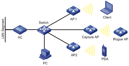
In a wireless network, it is difficult to locate signal interference and packet collision by debugging information or terminal display information of WLAN devices. WLAN sniffer facilitates the troubleshooting by using an AP as a packet sniffer to listen to, capture, and record wireless packets. The information about captured packets is stored in a CAP file.
As shown in Figure 1, enable WLAN sniffer on the Capture AP. The Capture AP listens to the wireless packets in the network, including the packets from other APs, rouge APs, and clients, and stores the captured packets in the specified CAP file. The administrator can download the CAP file to a PC for analysis.
Configuring WLAN sniffer
|
|
NOTE: Disable other services such as WLAN and mesh before you enable WLAN sniffer on the radio, and do not enable these services during the WLAN sniffer process. |
To configure WLAN sniffer:
|
Step |
Command |
Remarks |
|
1. Enter system view. |
system-view |
N/A |
|
2. Configure the maximum number of packets that can be captured by an AP. |
wlan capture packet-limit packet-limit |
Optional. By default the maximum number of packets that can be captured by an AP is 10000. · You are not allowed to change the maximum number of packets that can be captured by an AP during the WLAN sniffer process. · WLAN sniffer stops when the maximum number is reached. |
|
3. Specify the name of the CAP file to which the captured packets are saved. |
wlan capture file-name file-name |
Optional. CaptureRecord by default. · The file has a fixed extension .dmp, which is not configurable. · You are not allowed to change the name of the CAP file during the WLAN sniffer process. |
|
4. Enable WLAN sniffer on a radio of an AP. |
wlan capture start ap ap-name radio radio-number |
WLAN sniffer can be enabled for only one radio of an AP. The radio must have been enabled and its working channel has been manually specified. The AP that holds the radio must have been associated with the AC. WLAN sniffer can be enabled for only one radio of an AP. |
|
5. Disable WLAN sniffer. |
wlan capture stop |
Optional |
|
|
NOTE: · An auto AP does not support the WLAN sniffer function. · To enable WLAN sniffer on a radio, the AP must operate in normal mode and must be in Run state, and the working channel of the radio must be manually specified. · Disabling the sniffer-enabled radio, deleting the Capture AP, disconnecting the Capture AP from the AC, or disabling WLAN sniffer stops the sniffer operation. The captured packets are saved to the specified CAP file in the default storage medium. The default storage medium varies with device models. · The working mode of the AP cannot be changed with the work-mode monitor or device-detection enable command when it is capturing packets. |
Displaying and maintaining WLAN sniffer
|
Task |
Command |
Remarks |
|
Display information about WLAN sniffer enabled APs. |
display wlan capture [ | { begin | exclude | include } regular-expression ] |
Available in any view |
WLAN sniffer configuration example
Network requirements
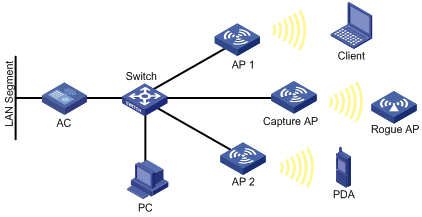
As shown in Figure 2, on the AC, enable WLAN sniffer for an AP to capture wireless packets.
Configuration procedure
|
|
NOTE: To enable WLAN sniffer on a radio, the AP must operate in normal mode and must be in Run state, and the working channel of the radio must be manually specified. The working channel for WLAN sniffer in this example is 11. |
1. Configure the WLAN sniffer function:
# Enable WLAN sniffer on Radio 2 of the AP named captureap.
<AC> system-view
[AC] wlan capture start ap captureap radio 2
2. Verify the configuration:
# Display information about the AP that is capturing packets. The output shows that Radio 2 on the AP is capturing packets.
[AC] display wlan capture
WLAN Capture
--------------------------------------------------------------------------------
AP : captureap
Radio : 2
Radio Mode : 802.11g
Channel : 11
Capture Limit : 5000
File Name : CaptureRecord.dmp
Status : Capturing
--------------------------------------------------------------------------------
Wireless location overview
|
|
NOTE: Support for this feature depends on your device model. |
Wireless location is a technology to locate, track and, monitor specific assets by using WiFi-based Radio Frequency Identification (RFID) and sensors. APs send collected Tag or MU messages to an AeroScout Engine (referred to as AE hereinafter). The AE performs location calculation and sends the results to the graphics software. You can view the location information of the assets in maps, forms, and reports provided by the software. The graphics software provides search, alert and query functions to facilitate your operations.
Wireless location can be applied to medical monitoring, asset management, and logistics, helping users effectively manage and monitor assets.
Architecture of the wireless location system
A wireless location system is composed of three parts: devices or sources to be located, location information receivers, and location systems.
· Devices or sources to be located include Tags (small, portable RFIDs, which are usually placed or glued to the assets to be located) of Aero Scout or Mobile Units (MU), and MUs (wireless terminals or devices running 802.11). The tags and MUs can send wireless messages periodically.
· Location information receivers include 802.11 APs.
· Location systems include the location server, AE calculation software, and different types of graphics software.
Wireless locating process
A wireless location system can locate wireless clients, APs, rogue APs, rogue clients, Tags and other devices supporting WLAN protocols. Except Tags, all wireless devices will be identified as MUs by the wireless location system.
1. Located devices send Tag or MU messages
An RFID sends tag messages that contain channel information over different channels. The RFID periodically sends messages over the configured channels first and then sends tag messages over channels 1, 6, and 11 in turn periodically.
Standard wireless devices send MU messages. An MU message does not contain channel information, so an AP cannot filter MU messages by channel number. The work is done by the location server by using a certain algorithm and rules.
2. The AP collects Tag and MU messages
The working mode of an AP determines how it collects Tag and MU messages:
? When the AP operates in monitor mode or hybrid mode, it can locate wireless clients or other wireless devices that are not associated with it.
? When the AP operates in normal mode, it can only locate wireless clients associated with it. The wireless location system considers wireless clients associated with the AP as wireless clients, and considers wireless clients or other wireless devices not associated with the AP as unknown devices.
|
|
NOTE: For more information about monitor mode and hybrid mode, see "Configuring WLAN security." |
The AP collects Tag and MU messages as follows.
· Upon receiving Tag messages (suppose that the Tags mode has been configured on the AC, and the location server has notified the AP to report Tag messages), the AP checks the Tag messages, encapsulates those passing the check and sends them to the location server. The AP encapsulates a Tag message by copying all its information (including message header and payload) except the multicast address and adding the BSSID, channel, timestamp, data rate, RSSI, SNR, and radio mode of the radio that received the Tag message.
· Upon receiving MU messages (suppose that the MUs mode has been configured on the AC, and the location server has notified the AP to report MU messages), the AP checks the messages, encapsulates those that pass the check and sends the messages to the location server. The AP encapsulates an MU message by copying its source address, Frame Control field, and Sequence Control field, and adding the BSSID, channel, timestamp, data rate, RSSI, SNR and radio mode of the radio that received the MU message.
· The location server calculates the locations of devices
After receiving Tag and MU messages from APs, the location server uses an algorithm to calculate the locations of the devices according to the RSSI, SNR, radio mode and data rate carried in the messages, and displays the locations on the imported map. Typically, the location server can calculate the locations as long as there are more than three APs (in monitor or hybrid mode) used to report Tag and MU messages.
Configuring wireless location
To perform wireless location, perform following configurations on the location server and the device:
· On the location server—Configure whether to locate Tags or MUs, Tag message multicast address, and dilution factor on the location server. These settings will be notified to the APs through configuration messages. For more information about location server and configuration parameters, see the location server manuals.
· On the wireless device—Configure the wireless location function.
|
|
NOTE: Configure the AP mode settings when you configure wireless location on the AC. |
To configure wireless location:
|
Step |
Command |
Remarks |
|
1. Enter system view. |
system-view |
N/A |
|
2. Enable wireless location. |
wlan rfid-tracking enable |
By default, wireless location is disabled. |
|
3. Specify the port number for the location server vendor. |
wlan rfid-tracking vendor-port vendor-port-value |
Optional. By default, the port number for the vendor is 1144. |
|
4. Specify the AP name and model, and enter AP template view. |
wlan ap ap-name [ model model-name [ id ap-id ] ] |
The AP model needs to be specified only when you create an AP template. |
|
5. Enter WLAN radio view. |
radio radio-id |
N/A |
|
6. Configure the wireless location mode for the radio. |
rfid-tracking mode { all | mu | tag } |
By default, no wireless location mode is configured for the radio. |
After the configuration, the AP waits for the configuration message sent by the location server, and after receiving that message, starts to receive and report Tag and MU messages.
In addition, the AP reports its IP address change and reboot events to the location server so that the location server can respond in time. To report a reboot event after reboot, the AP must use the IP address and port information of the location server stored in its flash. The AP maintains such information as follows:
· The AP updates the data in the flash after receiving a configuration message. To protect the flash, the AP does not update the flash immediately, but waits for 10 minutes. If it receives another configuration message before the 10 minutes elapse, the AP only updates the configuration information in the cache, and when the 10-minute timer expires, saves the information in the flash.
· If the AP reboots within 10 minutes since it receives the first configuration message, no server information is saved in the flash, so it does not send a reboot message to the location server.
Displaying and maintaining wireless location
|
Task |
Command |
Remarks |
|
Display wireless location radio information. |
display wlan rfid-tracking radio [ ap ap-name radio radio-id ] [ | { begin | exclude | include } regular-expression ] |
Available in any view |
Wireless location configuration example
Network requirements
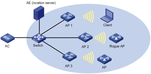
As shown in Figure 3, AP 1, AP 2, and AP 3 operate in monitor mode, and send collected tag and MU messages to the AE (the location server). The AE performs location calculation and sends the results to the graphics software. The software shows the location information of the rogue AP, APs, and clients in maps, forms, or reports.
Configuration procedure
1. Configure the AE:
? Configure the IP addresses of AP 1, AP 2, and AP 3 on the AE, or select broadcast for the AE to discover APs.
? Perform configuration related to wireless location on the AE.
2. Configure AP 1 to operate in monitor mode:
On the AC, configure AP 1, AP 2, and AP 3 to operate in monitor mode. AP 1, AP 2, and AP 3 are configured similarly, and this section only describes how to configure AP 1 for illustration.
# Create AP 1.
<AC> system-view
[AC] wlan ap ap1 model WA2220-AG
# Specify the serial ID for the AP.
[AC-wlan-ap-ap1] serial-id 210235A29G007C000020
# Configure the AP to operate in monitor mode.
[AC-wlan-ap-ap1] work-mode monitor
# Enable the radio.
[AC-wlan-ap-ap1] radio 1
[AC-wlan-ap-ap1-radio-1] radio enable
[AC-wlan-ap-ap1-radio-1] return
# Enable wireless location.
<AC> system-view
[AC] wlan rfid-tracking enable
# Configure the wireless location mode.
[AC] wlan ap ap1
[AC-wlan-ap-ap1] radio 1
[AC-wlan-ap-ap1-radio-1] rfid-tracking mode all
[AC-wlan-ap-ap1-radio-1] return
3. Verify the configuration:
# Display wireless location radio information.
<AC> display wlan rfid-tracking radio
WLAN RFID Tracking
--------------------------------------------------------------------------------
AP Radio Mode
--------------------------------------------------------------------------------
ap1 1 MU/Tag
ap1 2 N/A
--------------------------------------------------------------------------------
# You can view the location information of the rogue AP, APs, and clients by maps, forms or reports provided by the graphics software.
Configuration guidelines
· To implement wireless location, configure at least three APs to operate in monitor or hybrid mode.
· An AP monitors clients on different channels periodically. If the Tag message sending interval is configured as 1 second, the AP scans and reports Tag messages every half a minute. If higher location efficiency is required, you can set the Tag sending interval to the smallest value, 124 milliseconds on the AE.