- Table of Contents
-
- 02-WLAN Configuration Guide
- 00-Preface
- 01-WLAN Interface Configuration
- 02-WLAN Service Configuration
- 03-WLAN Security Configuration
- 04-WLAN Roaming Configuration
- 05-WLAN RRM Configuration
- 06-WLAN IDS Configuration
- 07-WLAN QoS Configuration
- 08-WLAN Mesh Link Configuration
- 09-WLAN Optimization Configuration
- 10-Advanced WLAN Configuration
- Related Documents
-
| Title | Size | Download |
|---|---|---|
| 09-WLAN Optimization Configuration | 247.57 KB |
Contents
Rejecting wireless clients with low RSSI
Enabling 802.11n packet suppression
Enabling traffic shaping based on link status
Configuring the rate algorithm
Enabling channel sharing adjustment
Enabling channel reuse adjustment
Disabling buffering of multicasts and broadcasts
Enabling multi-service optimization
Enabling the AP to trigger client re-connection
Enabling the AP to receive all broadcasts
Enabling the green-AP function
Configuring a power supply mode for the AP
WLAN optimization configuration examples
Optimizing a high-density WLAN
Optimizing a WLAN with multicast application
Enabling packet-based TPC for a WLAN
Proper channel planning and power control policies during WLAN deployment are very important for good performance. In live WLAN networks, however, channel overlapping, collisions, and interference can easily occur because the none-overlapping channels are limited but the number of WLAN devices always increases.
This chapter describes a set of features used to improve the quality and stability of live WLAN networks.
|
|
NOTE: · A feature applied in different WLANs may have different effects because there are many factors impacting WLAN performance. · There is no fixed combination of features for optimizing a specific WLAN. Select the features most suitable for your WLAN. · The features described in this chapter cannot significantly change the performance of a WLAN. In practice, if the features used can improve the WLAN performance by 3%, the optimization is considered successful. |
Rejecting wireless clients with low RSSI
Wireless clients whose packets have low received signal strength indicator (RSSI) cannot get good service or performance but they occupy wireless channels especially when they are downloading huge amounts of data, affecting other clients with high RSSI.
This task configures an RSSI so that clients whose RSSI is lower than the configured RSSI cannot access the WLAN.
|
|
CAUTION: This feature disables wireless clients whose RSSI is lower than the specified RSSI from accessing the WLAN. |
To configure the client-reject signal threshold:
|
Step |
Command |
Remarks |
|
1. Enter system view. |
system-view |
N/A |
|
2. Configure the client-reject RSSI. |
wlan option client-reject rssi |
Not configured by default. |
Enabling fair scheduling
The fair scheduling feature sends a packet destined to a different client each time to ensure fairness. This mechanism avoids the situation where some clients occupy the output queues on an AP for a long time when they are downloading bulky data by using applications such as BT and video on demand.
To enable fair scheduling:
|
Step |
Command |
Remarks |
|
1. Enter system view. |
system-view |
N/A |
|
2. Enable fair scheduling. |
wlan option fair-schedule enable |
Enabled by default. |
Ignoring weak signals
When an AP detects weak signals from a remote client, it considers the channel is occupied and does not forward other packets.
This feature can avoid the impact of weak signals by enabling an AP to ignore packets whose signal strength is lower than a specific RSSI.
|
|
NOTE: Although this feature increases the forwarding rate of the AP, it may cause interference or collisions with other devices working on the same channel. |
To ignore signals weaker than an RSSI:
|
Step |
Command |
Remarks |
|
1. Enter system view. |
system-view |
N/A |
|
2. Ignore signals weaker than an RSSI. |
wlan option signal-ignore rssi |
Not configured by default. |
Enabling 802.11n packet suppression
802.11n introduces the A-MPDU frame format. By using only one PHY header, each A-MPDU can accommodate multiple MPDUs that have their PHY headers removed. This reduces the overhead in transmission and the number of ACK frames to be used, and improves network throughput.
In practice, however, 802.11gn, 802.11g, and 802.11b clients may coexist, and the MPDU aggregation capability of 802.11n affects the performance of other types of clients.
This feature can suppress 802.11n packets by defining two thresholds, a maximum number of aggregated MPDUs and a maximum A-MPDU length. The two thresholds take effect at the same time. If either threshold is reached, the AP stops aggregation and sends the A-MPDU.
|
|
NOTE: This feature reduces the impact of 802.11n clients to other types of clients. |
To configure 802.11 packet suppression:
|
Step |
Command |
Remarks |
|
1. Enter system view. |
system-view |
N/A |
|
2. Enable 802.11 packet suppression and specify the thresholds. |
wlan option dot11n-restraint packet-number max-packets packet-length max-length |
Not enabled by default. |
Enabling traffic shaping based on link status
Clients near an AP have high RSSI while clients at the border of the coverage area of the AP have low RSSI. When the network is busy, the weak clients occupy the working channel of the AP for a long time due to their lower speeds and affect the clients with good RSSI.
The traffic shaping feature identifies the weak clients by checking their signal strength and packet loss ratio, and dynamically controls their packet throughput to reduce their impact to other clients.
To enable traffic shaping:
|
Step |
Command |
Remarks |
|
1. Enter system view. |
system-view |
N/A |
|
2. Enable traffic shaping based on link status. |
wlan option traffic-shaping enable |
Disabled by default. |
Configuring the rate algorithm
802.11 protocols each support a set of rates. For example, 802.11g supports the rates of 1, 2, 5.5, 11, 6, 9, 12, 18, 24, 36, 48, and 54. An 802.11 protocol dynamic selects a proper rate based on the channel quality and history data.
A rate algorithm applied on a radio can avoid improper rate adjustments that can impact network operation. The system supports multiple rate algorithms, including ARR, HDD, HDD2, and LPL. The default rate algorithm ARR is applicable in various scenarios.
|
|
NOTE: You can configure the rate algorithm only on 802.11a/b/g radios. |
To configure the rate algorithm:
|
Step |
Command |
Remarks |
|
1. Enter system view. |
system-view |
N/A |
|
2. Configure the rate algorithm. |
wlan option rate-algorithm { arr band | hdd | hdd2 | lpl packet-count up-threshold down-threshold } |
ARR by default. |
Enabling channel sharing adjustment
The non-overlapping channels of an 802.11 protocol are very limited. For example, 802.11g has only three non-overlapping channels. Therefore, an AP can easily detect other APs working on the same channel, especially in a high-density WLAN. Channel overlapping causes collisions and interference and reduces WLAN performance. Proper channel planning and power control policies during WLAN deployment are the major methods to reduce overlapping. In addition, you can perform this task in a live network to reduce the impact of overlapping.
This task configures a power level. If an AP detects signals stronger than the power level, the AP considers the channel is occupied and does not send packets. If the detected signals are weaker than the power level, the AP sends the packets. This mechanism avoids collisions and interference.
|
|
CAUTION: Do not enable channel sharing adjustment and channel reuse adjustment at the same time. |
To enable channel sharing adjustment:
|
Step |
Command |
Remarks |
|
1. Enter system view. |
system-view |
N/A |
|
2. Enable channel sharing adjustment and specify the power level. |
wlan option channel-share power-level |
By default, the power level is 30. |
Enabling channel reuse adjustment
WLAN devices within a space share the same media. They use collision avoidance and contention mechanisms to send frames over channels. As the number of devices working on a channel increases, the whole WLAN performance degrades. To solve the problem, make proper channel planning and power control policies before WLAN deployment. In addition, you can perform this task in a live network to improve the performance of APs working on the same channel.
This task configures a channel reuse level. An AP ignores packets whose RSSI is lower than the reuse level so that it can get more radio frequency resources and higher speed.
|
|
CAUTION: · Do not enable channel sharing adjustment and channel reuse adjustment at the same time. · Enabling channel reuse adjustment may result in increased hidden nodes. |
To enable channel reuse adjustment:
|
Step |
Command |
Remarks |
|
1. Enter system view. |
system-view |
N/A |
|
2. Enable channel reuse adjustment and specify the reuse level. |
wlan option channel-reuse reuse-level |
Not enabled by default. |
Disabling buffering of multicasts and broadcasts
If one of the clients associated with an AP is in sleep state, the AC stops sending all broadcast and multicast packets and buffers them before it sends the next Beacon frame. This mechanism affects the performance of multicast applications.
You can perform this task to disable buffering multicast and broadcast packets. The AC directly sends all broadcast and multicast packets regardless of whether an associated client is in sleep state.
|
|
NOTE: · Set the power management parameter to the maximum value on wireless clients to prevent them entering sleep state. · Disabling buffering of multicasts and broadcasts improves multicast performance in specific scenarios such as multicast-based training, but clients in sleep state will lose some broadcast and multicast packets. . |
To disable buffering of multicasts and broadcasts:
|
Step |
Command |
Remarks |
|
1. Enter system view. |
system-view |
N/A |
|
2. Disable buffering of multicasts and broadcasts. |
undo wlan option broadcast-buffer enable |
Enabled by default. |
Enabling multi-service optimization
This feature can maximize the overall performance of multiple WLAN services provided by an 802.11n AP.
|
|
CAUTION: · Do not enable this feature on an AP providing only one or two services. Otherwise, BSSID changes will occur on the radio. · Only the WA2612-AGN and WA2610-AGN support this feature. |
To enable multi-service optimization:
|
Step |
Command |
Remarks |
|
1. Enter system view. |
system-view |
N/A |
|
2. Enable multi-service optimization. |
wlan option multi-service enable |
Not enabled by default. |
Enabling AP blinking
Perform this task to enable fit APs to blink different colors to show whether they have been associated with the AC. This feature is very useful for AP registration state inspection because fit APs are often installed in high or hidden positions.
For information about AP blinking colors and their meanings, see the corresponding installation guide.
|
|
NOTE: · Disable this feature after you complete AP registration state inspection. · The WA3600 series, WA2620i-AGN, and WA2610i-GN support this feature. |
To enable AP blinking:
|
Step |
Command |
Remarks |
|
1. Enter system view. |
system-view |
N/A |
|
2. Enable AP blinking. |
wlan option blink enable |
Disabled by default. |
Enabling packet-based TPC
An AP usually uses a high and fixed transmit power to cover an area as large as possible. This mechanism is not energy saving.
This feature enables an AP to dynamically perform transmit power control (TPC) on a per packet basis. For example, the AP reduces the transmit power when it sends packets to a client with high RSSI. This feature can reduce power consumption, radiation, and interference, improving user experience.
To enable TPC on a per packet basis:
|
Step |
Command |
Remarks |
|
1. Enter system view. |
system-view |
N/A |
|
2. Enable TPC on a per packet basis. |
wlan option tpc enable |
Disabled by default. |
Enabling the AP to trigger client re-connection
This feature enables an AP to send unsolicited de-authentication frames to a client when the signal strength of the client is lower than the specified RSSI value so that the client can re-connect to the AP or roam to another AP.
To enable an AP to trigger client re-connection:
|
Step |
Command |
Remarks |
|
1. Enter system view. |
system-view |
N/A |
|
2. Enable an AP to trigger client re-connection. |
wlan option client-reconnect-trigger rssi signal-check |
Disabled by default. |
Enabling the AP to receive all broadcasts
|
|
NOTE: · Support for this feature depends on the AP model. APs that do not support this feature will ignore this configuration obtained from the AC. · Disable this feature when it is not needed because receiving all broadcasts affects the normal operation of an AP. |
This feature enables an AP to receive all broadcasts so that the AP can detect spoofing attacks for all BSSs.
To enable the AP to receive all broadcasts:
|
Step |
Command |
Remarks |
|
1. Enter system view. |
system-view |
N/A |
|
2. Enable the AP to receive all broadcasts. |
wlan option rx-broadcast-all enable |
Disabled by default. |
Enabling the green-AP function
This feature enables an AP to use one radio when no clients are associated with it to save energy.
To enable the green-AP function:
|
Step |
Command |
Remarks |
|
1. Enter system view. |
system-view |
N/A |
|
2. Enable the green-AP function. |
wlan option green-ap enable |
By default, the green-AP function is disabled. |
Configuring a power supply mode for the AP
The AP supports local, PoE, and PoE+ power supply modes. H3C recommends that you use the local or PoE+ power supply mode to achieve better performance.
To configure a power supply mode for the AP:
|
Step |
Command |
Remarks |
|
1. Enter system view. |
system-view |
N/A |
|
2. Configure a power supply mode for the AP. |
wlan option power-supply { local | poe | poeplus } |
Optional. By default, the power supply mode for the AP is local. This command takes effect only on the WA3620i-AGN and WA3628i-AGN APs. |
WLAN optimization configuration examples
Optimizing a high-density WLAN
Network requirements
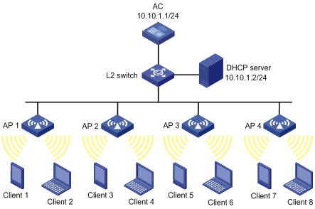
Deploy a WLAN in a six-floor dormitory building. Each floor has 20 dormitory rooms, and each room has an average of four wireless clients. Deploy four APs at each floor, and connect them to an AC through a Layer-2 switch in the wiring closet of the floor.
In addition, configure the following features to optimize the WLAN:
· Reject wireless clients with low RSSI
· Ignore weak signals
· Enable traffic shaping based on link status
· Enable fair scheduling

Configuration procedure
1. Configure IP addresses and masks for devices as shown in Figure 1. (Details not shown.)
2. Configure the AC:
Configure a WLAN service. For more information about WLAN service configuration, see "Configuring WLAN services". The following configures a clear-type WLAN service.
# Add interface WLAN-ESS 1 to VLAN 100.
<AC> system-view
[AC] interface WLAN-ESS 1
[AC-WLAN-ESS1] port access vlan 100
[AC-WLAN-ESS1] quit
# Create clear-type service template 1, specify its SSID as Clear-Test, bind the template with WLAN-ESS1, and enable the template.
[AC] wlan service-template 1 clear
[AC-wlan-st-1] ssid Clear-Test
[AC-wlan-st-1] bind WLAN-ESS 1
[AC-wlan-st-1] service-template enable
[AC-wlan-st-1] quit
3. Configure the APs:
Configure all the APs on the AC. The following takes an AP as an example.
# Create AP template ap1 with the model as WA2100, and specify the serial ID as 210235A29G007C000020.
[AC] wlan ap ap1 model wa2100
[AC-wlan-ap-ap1] serial-id 210235A29G007C000020
# Apply the service template 1 to radio 1 and enable the radio.
[AC-wlan-ap-ap1] radio 1
[AC-wlan-ap-ap1-radio-1] service-template 1
[AC-wlan-ap-ap1-radio-1] radio enable
[AC-wlan-ap-ap1-radio-1] quit
[AC-wlan-ap-ap1] quit
4. Configure WLAN optimization features:
# Reject clients whose signal strength is lower than 15 dBm.
[AC] wlan option client-reject 15
# Ignore signals with strength lower than 15 dBm.
[AC] wlan option signal-ignore 15
# Enable traffic shaping based on link status and enable fair scheduling.
[AC] wlan option traffic-shaping enable
[AC] wlan option fair-schedule enable
Optimizing a WLAN with multicast application
Network requirements
Deploy an AC and five dual-band APs in a training center that has multiple training rooms and provides multicast-based training programs. Use WLAN RRM to set the multicast rate.
In addition, disable buffering of multicasts and broadcasts for the WLAN so that the clients can receive multicast traffic in real time.
|
|
NOTE: H3C recommends that you install a dual-band wireless network interface card and set the power management parameter to the maximum on each client to prevent the clients entering sleep state. |

Configuration procedure
1. Configure IP addresses for devices as shown in Figure 2. (Details not shown.)
2. Configure the AC:
Configure a WLAN service. For more information about WLAN service configuration, see "Configuring WLAN services." The following configures a clear-type WLAN service.
# Add interface WLAN-ESS 1 to VLAN 100.
<AC> system-view
[AC] interface WLAN-ESS 1
[AC-WLAN-ESS1] port access vlan 100
[AC-WLAN-ESS1] quit
# Create clear-type service template 1, specify its SSID as Clear-Test, bind the template with WLAN-ESS1, and enable the template.
[AC] wlan service-template 1 clear
[AC-wlan-st-1] ssid Clear-Test
[AC-wlan-st-1] bind WLAN-ESS 1
[AC-wlan-st-1] service-template enable
[AC-wlan-st-1] quit
3. Configure the APs:
Configure all the APs on the AC. The following takes an AP as an example.
# Create AP template ap1 with the model as WA2620-AGN, and specify the serial ID as 210235A29F007C000151.
[AC] wlan ap ap1 model wa2620-agn
[AC-wlan-ap-ap1] serial-id 210235A29G007C000020
# Apply the service template 1 to radio 1, specify its working channel as 149, and enable radio 1.
[AC-wlan-ap-ap1] radio 1
[AC-wlan-ap-ap1-radio-1] channel 149
[AC-wlan-ap-ap1-radio-1] service-template 1
[AC-wlan-ap-ap1-radio-1] radio enable
# Apply the service template 1 to radio 2, specify its working channel as 1, and enable radio 2.
[AC-wlan-ap-ap1-radio-1] radio 2
[AC-wlan-ap-ap1-radio-2] channel 1
[AC-wlan-ap-ap1-radio-2] service-template 1
[AC-wlan-ap-ap1-radio-2] radio enable
4. Set the multicast rate:
# Log in to the Web interface of the AC, and enter the Rate page as shown in Figure 3. Set the multicast rate to 24 Mbps for 802.11g and 802.11a, and click Apply.
Figure 3 Configuring the multicast rate

5. Disable buffering of multicast and broadcast packets:
[AC] undo wlan option broadcast-buffer enable
Optimizing an 802.11n WLAN
Network requirements
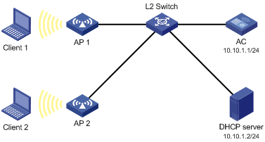
As shown in Figure 4, all the clients and APs get their IP addresses from the DHCP server. Client 1 using 802.11n associates with AP 1, and Client 2 using 802.11g associates with AP 2.
Enable 802.11n packet suppression and enable traffic shaping based on link status so that Client 1 does not affect Client 2.

Configuration procedure
1. Configure IP addresses and masks for devices as shown in Figure 4. (Details not shown.)
2. Configure the AC:
Configure a WLAN service. For more information about WLAN service configuration, see "Configuring WLAN service." The following configures a clear-type WLAN service.
# Add interface WLAN-ESS 1 to VLAN 100.
<AC> system-view
[AC] interface WLAN-ESS 1
[AC-WLAN-ESS1] port access vlan 100
[AC-WLAN-ESS1] quit
# Create clear-type service template 1, specify its SSID as Clear-Test, bind the template with WLAN-ESS1, and enable the template.
[AC] wlan service-template 1 clear
[AC-wlan-st-1] ssid Clear-Test
[AC-wlan-st-1] bind WLAN-ESS 1
[AC-wlan-st-1] service-template enable
[AC-wlan-st-1] quit
3. Configure the APs:
Configure all the APs on the AC. The following takes an AP as an example.
# Create AP template ap1 with the model as WA2620-AGN, and specify the serial ID as 219801A0A8909AG00046.
[AC] wlan ap ap1 model wa2620-agn
[AC-wlan-ap-ap1] serial-id 219801A0A8909AG00046
# Apply the service template 1 to radio 1 and enable radio 1.
[AC-wlan-ap-ap1] radio 1
[AC-wlan-ap-ap1-radio-1] service-template 1
[AC-wlan-ap-ap1-radio-1] radio enable
# Apply the service template 1 to radio 2 and enable radio 2.
[AC-wlan-ap-ap1-radio-1] radio 2
[AC-wlan-ap-ap1-radio-2] service-template 1
[AC-wlan-ap-ap1-radio-2] radio enable
[AC-wlan-ap-ap1-radio-2] quit
[AC-wlan-ap-ap1] quit
4. Configure WLAN optimization:
# Enable 802.11n packet suppression and set the maximum number of MPDUs aggregated in an A-MPDU as six, and set the maximum A-MPDU length as 5000 bytes.
[AC] wlan option dot11n-restraint packet-number 6 packet-length 5000
# Enable traffic shaping based on link status.
[AC] wlan option traffic-shaping enable
Optimizing some APs in a WLAN
Network requirements
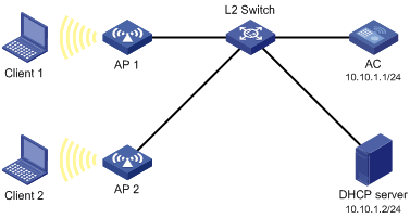
As shown in Figure 5, all the clients and APs get their IP addresses from the DHCP server. Client 1 is close to AP 1, and Client 2 is close to AP 2.
Configure the following optimization features on AP 1:
· Reject wireless clients with low RSSI
· Ignore weak signals
· Enable traffic shaping based on link status
· Enable fair scheduling

Configuration procedure
1. Configure IP addresses and masks for devices as shown in Figure 5. (Details not shown.)
2. Configure the AC:
Configure a WLAN service. For more information about WLAN service configuration, see "Configuring WLAN services." The following configures a clear-type WLAN service.
# Add interface WLAN-ESS 1 to VLAN 100.
<AC> system-view
[AC] interface WLAN-ESS 1
[AC-WLAN-ESS1] port access vlan 100
[AC-WLAN-ESS1] quit
# Create clear-type service template 1, specify its SSID as Clear-Test, bind the template with WLAN-ESS1, and enable the template.
[AC] wlan service-template 1 clear
[AC-wlan-st-1] ssid Clear-Test
[AC-wlan-st-1] bind WLAN-ESS 1
[AC-wlan-st-1] service-template enable
[AC-wlan-st-1] quit
3. Create a configuration file named aplocalrule.txt for AP 1:
# The configuration file contains the following settings.
wlan option client-reject 15 //Reject clients with RSSI lower than 15
wlan option signal-ignore 15 //Ignore signals weaker than 15
wlan option traffic-shaping enable //Enable traffic shaping based on link status
wlan option fair-schedule enable //Enable fair scheduling
4. Configure the APs:
# Create AP template ap1 with the model as WA2100, specify the serial ID as 210235A29G007C000020, and bind the configuration file aplocalrule.txt to AP 1.
[AC] wlan ap ap1 model wa2100
[AC-wlan-ap-ap1] serial-id 210235A29G007C000020
[AC-wlan-ap-ap1] map-configuration aplocalrule.txt
# Apply the service template 1 to radio 1 and enable radio 1.
[AC-wlan-ap-ap1] radio 1
[AC-wlan-ap-ap1-radio-1] service-template 1
[AC-wlan-ap-ap1-radio-1] radio enable
# Create AP template ap2 with the model as WA2100, and specify the serial ID as 210235A29G007C000021.
[AC] wlan ap ap2 model wa2100
[AC-wlan-ap-ap2] serial-id 210235A29G007C000021
# Apply the service template 1 to radio 1 and enable radio 1.
[AC-wlan-ap-ap2] radio 1
[AC-wlan-ap-ap2-radio-1] service-template 1
[AC-wlan-ap-ap2-radio-1] radio enable
5. Verify the configuration:
Use Client 1 and Client 2 to access the WLAN, and then take the two clients far from the APs until their RSSI displayed with the display wlan client verbose command is about 10. Disconnect and then reconnect the two clients. Client 2 can access the WLAN while Client 1 cannot.
Enabling packet-based TPC for a WLAN
Network requirements
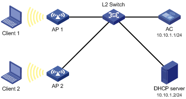
As shown in Figure 6, all the clients and APs get their IP addresses from the DHCP server.
Configure packet-based TPC on the AC to dynamically adjust transmit power on a per packet basis.

Configuration procedure
1. Configure IP addresses and masks for devices as shown in Figure 6. (Details not shown.)
2. Configure the AC:
Configure a WLAN service. For more information about WLAN service configuration, see "Configuring WLAN services." The following configures a clear-type WLAN service.
# Add interface WLAN-ESS 1 to VLAN 100.
<AC> system-view
[AC] interface WLAN-ESS 1
[AC-WLAN-ESS1] port access vlan 100
[AC-WLAN-ESS1] quit
# Create clear-type service template 1, specify its SSID as Clear-Test, bind the template with WLAN-ESS1, and enable the template.
[AC] wlan service-template 1 clear
[AC-wlan-st-1] ssid Clear-Test
[AC-wlan-st-1] bind WLAN-ESS 1
[AC-wlan-st-1] service-template enable
[AC-wlan-st-1] quit
3. Configure the APs:
Configure all the APs on the AC. The following takes an AP as an example.
# Create AP template ap1 with the model as WA2620-AGN, and specify the serial ID as 219801A0A8909AG0004.
[AC] wlan ap ap1 model wa2620-agn
[AC-wlan-ap-ap1] serial-id 219801A0A8909AG00046
# Apply the service template 1 to radio 1 and enable radio 1.
[AC-wlan-ap-ap1] radio 1
[AC-wlan-ap-ap1-radio-1] service-template 1
[AC-wlan-ap-ap1-radio-1] radio enable
# Apply the service template 1 to radio 2 and enable radio 2.
[AC-wlan-ap-ap1-radio-1] radio 2
[AC-wlan-ap-ap1-radio-2] service-template 1
[AC-wlan-ap-ap1-radio-2] radio enable
[AC-wlan-ap-ap1-radio-2] quit
[AC-wlan-ap-ap1] quit
4. Enable packet-based TPC:
[AC] wlan option tpc enable

