- Table of Contents
-
- 02-WLAN Configuration Guide
- 00-Preface
- 01-WLAN Interface Configuration
- 02-WLAN Service Configuration
- 03-WLAN Security Configuration
- 04-WLAN Roaming Configuration
- 05-WLAN RRM Configuration
- 06-WLAN IDS Configuration
- 07-WLAN QoS Configuration
- 08-WLAN Mesh Link Configuration
- 09-WLAN Optimization Configuration
- 10-Advanced WLAN Configuration
- Related Documents
-
| Title | Size | Download |
|---|---|---|
| 02-WLAN Service Configuration | 829.07 KB |
Configuring software automatic update
Configuring a WLAN service template
Configuring basic network parameters for an AP
Configuring AC-AP tunnel dual-link
Enabling CAPWAP/LWAPP tunnel encryption with IPsec
Enabling automatic creation of radio policies
Displaying and maintaining WLAN service
Introduction to VLAN-based user isolation
Configuring VLAN-based user isolation
Introduction to SSID-based user isolation
Configuring SSID-based user isolation
Isolating broadcasts and multicasts from wired users to wireless users
Displaying and maintaining user isolation
Configuring AP group for AP based access control
Applying the AP group in a user profile
Displaying and maintaining AP group·
Configuring SSID-based access control
Configuring the VLAN ID of the port connected to the other AC
Configuring the interval for sending heartbeat messages
Configuring the delay for the AP to switch from the master AC to the backup AC
Displaying the AC connection state
WLAN service configuration examples
WLAN service configuration example
WLAN auto-AP configuration example
AC-AP tunnel dual-link configuration example
Configuration example for CAPWAP tunnel encryption with IPsec
Example for configuring fit APs on an AC
User isolation configuration example
Uplink detection configuration example
AP group configuration examples
AP group configuration without roaming
AP group configuration for inter-AC roaming·
WLAN service overview
A wireless Local Area Network (WLAN) can provide the following services.
· WLAN client connectivity to conventional 802.3 LANs
· Secured WLAN access with different authentication and encryption methods
· Seamless roaming of WLAN clients in a mobility domain
Terminology
Client
A PC or laptop with a wireless Network Interface Card (NIC), or any WiFi-capable terminal
Access point (AP)
An AP bridges frames between wireless and wired networks.
Access controller (AC)
An AC can control and manage all APs in a WLAN. The AC communicates with an authentication server for WLAN client authentication.
SSID
Service set identifier. A client scans all networks at first, and then selects a specific SSID to connect to a specific wireless network.
Wireless medium
A medium used for transmitting frames between wireless clients. Radio frequency is used as the wireless medium in the WLAN system.
Split MAC
In split MAC mode, APs and ACs manage different services. An AP manages real-time services, such as beacon generation, power management, fragmentation, defragmentation, scheduling, and queuing. An AC manages services related to packet distribution, association, dissociation, reassociation, key management, 802.1X, EAP, and 802.11e.
Wireless client access
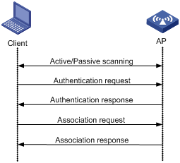
A wireless client access process involves three steps: active/passive scanning surrounding wireless services, authentication, and association, as shown in Figure 1.
Figure 1 Establishing a client access
Scanning
A wireless client gets surrounding wireless network information in two ways, passive scanning and active scanning. With active scanning, a wireless actively sends a probe request frame, and gets network signals from received probe response frames. With passive scanning, a wireless client gets wireless network information by listening to Beacon frames sent by surrounding APs.
Actually, when a wireless client operates, it usually uses both passive scanning and active scanning to get information about surrounding wireless networks.
1. Active scanning
When a wireless client operates, it periodically searches for (scans) surrounding wireless networks. Active scanning falls into two modes according to whether a specified SSID is carried in a probe request.
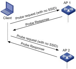
¡ A client sends a probe request with no SSID (the SSID IE length is 0): The client periodically sends a probe request frame on each of its supported channels to scan wireless networks. APs that receive the probe request send a probe response, which carries the available wireless network information. The client associates with the AP with the strongest signal. This active scanning mode enables a client to actively get acquainted with the available wireless services and select to access the proper wireless network as needed. The active scanning process of a wireless client is as shown in Figure 2.
Figure 2 Active scanning (the SSID of the probe request is null, or, no SSID information is carried)
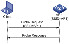
¡ A client sends a probe request (with a specified SSID): When the wireless client is configured to access a specific wireless network or has already successfully accessed a wireless network, the client periodically sends a probe request carrying the specified SSID of the configured or connected wireless network. When an AP that can provide the wireless service with the specified SSID receives the probe request, it sends a probe response. This active scanning mode enables a client to access a specified wireless network. The active scanning process is as shown in Figure 3.
Figure 3 Active scanning (the probe request carries the specified SSID AP 1)
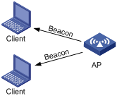
2. Passive scanning
Passive scanning discovers surrounding wireless networks by listening to the beacon frames periodically sent by APs. Passive scanning is used by a client when it wants to save battery power. Typically, VoIP clients adopt the passive scanning mode. The passive scanning process is as shown in Figure 4.
Authentication
To secure wireless links, the wireless clients must be authenticated before accessing the AP, and only wireless clients passing the authentication can be associated with the AP. 802.11 links define two authentication mechanisms: open system authentication and shared key authentication.
· Open system authentication
· Shared key authentication
For more information about the two authentication mechanisms, see "Configuring WLAN security."
Association
A client that wants to access a wireless network via an AP must be associated with that AP. Once the client chooses a compatible network with a specified SSID and passes the link authentication to an AP, it sends an association request frame to the AP. The AP detects the capability information carried in the association request frame, determines the capability supported by the wireless client, and sends an association response to the client to notify the client of the association result. Usually, a client can associate with only one AP at a time, and an association process is always initiated by the client.
Other related procedures
1. De-authentication
A de-authentication frame can be sent by either an AP or wireless client to break an existing link. In a wireless system, de-authentication can occur due to many reasons, such as:
¡ Receiving an association/disassociation frame from a client which is unauthenticated.
¡ Receiving a data frame from a client which is unauthenticated.
¡ Receiving a PS-poll frame from a client which is unauthenticated.
2. Dissociation
A dissociation frame can be sent by an AP or a wireless client to break the current wireless link. In the wireless system, dissociation can occur due to many reasons, such as:
¡ Receiving a data frame from a client which is authenticated and unassociated.
¡ Receiving a PS-Poll frame from a client which is authenticated and unassociated.
IEEE 802.11 overview
The WLAN-MAC primarily includes the implementation of IEEE 802.11 MAC layer functionality. Various modes of MAC are:
· Local-MAC Architecture
· Split-MAC Architecture
In local-MAC architecture, most WLAN services are provided by the AP only. Currently, local-MAC architecture is not supported.
In split-MAC architecture, the AP and the AC manage different services.
AC-AP tunnel overview
An AC and AP communicate with each other over an AC-AP tunnel. The AC-AP tunnel uses a generic encapsulation and transport mechanism, as shown in Figure 5.
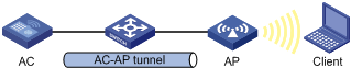
The AC-AP tunnel is built on a standard client/server model and employs UDP. Data packets to be sent to the AC are encapsulated, and these packets can be raw 802.11 packets. Remote AP configuration and management, and WLAN and mobile management are also supported.
The AC-AP tunnel supports both IPv4 and IPv6.
AC-AP tunnel link backup
Dual link establishment
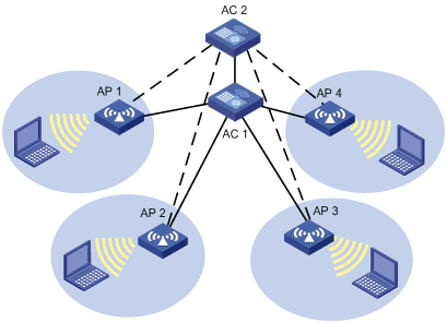
To achieve AC backup, an AP can establish two tunnels with two ACs that must have the same AP configurations. Only the AC which works in master mode provides services to all the APs in the network and the subordinate AC acts as the backup AC. If the master AC fails, APs should quickly use the services provided by the subordinate AC. A heartbeat mechanism is used between these two ACs, which ensures that failure of the master will be detected quickly by the backup AC.

In Figure 6, AC 1 is working in master mode and providing services to AP 1, AP 2, AP 3 and AP 4. AC 2 is working in subordinate mode. APs are connected to AC 2 through subordinate tunnels. AC 1 and AC 2 can be configured as backup for each other and start master/subordinate detection. When AC 2 detects AC 1 is down, AC 2 quickly converts the work mode from subordinate to master. All APs which are connected to AC 2 through subordinate tunnels transform the tunnels to master tunnels and use AC 2 as the master AC. Once AC 1 is reachable again, it remains the backup.
Primary AC recovery
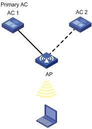
In Figure 7, AC 1 acting as the primary AC is the master (which has the connection priority of 7), and it establishes an AC-AP tunnel connection with the AP; AC 2 acts as the subordinate AC. If AC 1 goes down, AC 2 will act as the master until recovery of the AC-AP tunnel. This means once AC 1 is reachable again, the AP will establish a connection with AC 1 acting as the primary AC and disconnect from AC 2.
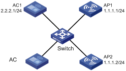
Dual work mode
Figure 8 Dual work mode
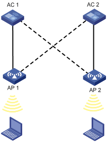
Dual work mode indicates that an AC can provide both master and subordinate connections. An AC will act as the master for some APs and act as the subordinate for some other APs. In this scenario, AC 1 acts as the master for AP 1 and subordinate for AP 2. Similarly, AC 2 acts as the master for AP 2 and subordinate for AP 1.
WLAN topologies
WLAN topologies include:
· Single/Multi BSS
· Single/Multi-ESS
· VLAN-based WLAN
· Centralized WLAN
Single/Multi BSS
The coverage of an AP is a basic service set (BSS). Each BSS is identified by a Basic Service Set Identifier (BSSID). The most basic WLAN network can be established with only one BSS. All wireless clients associate with the same BSS. If these clients have the same authorization, they can communicate with each other. Figure 9 shows a single-BSS WLAN.
Figure 9 Single BSS network
Communications between clients within the same BSS are carried out through the AP and the AC. To implement multi-BSS, you simply need to add APs.
Single/Multi-ESS
All the clients under the same logical administration form an extended service set (ESS). The clients can communicate with each other and reach a host in the Internet. This multi-ESS topology describes a scenario where more than one ESS exists. When a mobile client joins the AP, it can join one of the available ESSs. Figure 10 shows a multi-ESS network.
Figure 10 Multi-ESS network
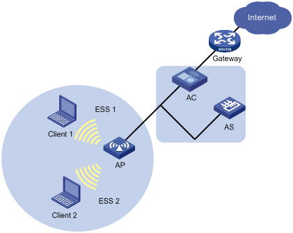
Generally, an AP can provide more than one ESS at the same time. The configuration of ESS is distributed mainly from AC to AP, and the AP can broadcast the current information of ESS by beacon or probe response frames. Clients can select an ESS in which it is interested to join.
Different ESS domains can be configured on the AC. The AC can be configured to allow associated APs to accept clients in these ESS domains once their credentials are accepted.
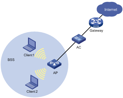
Centralized WLAN
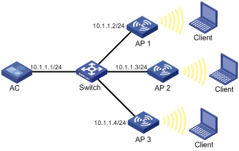
Centralized WLAN is a unified solution for wireless local area networks. Figure 11 shows a centralized WLAN network.
Figure 11 Centralized WLAN network
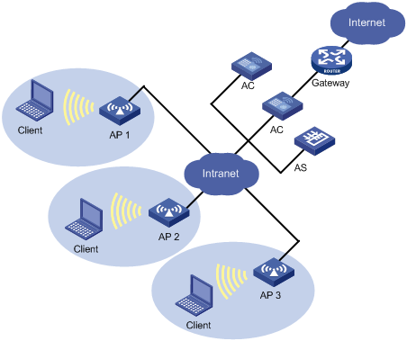
In this network, there are two ACs and three APs. An AP can connect with an AC directly, or over a Layer 2 or Layer 3 network. The other AC serves as the backup.
During initialization, an AP obtains its basic network configuration parameters, such as its own IP address, gateway address, domain name and DNS server address from a DHCP server.
An AP uses a discovery mechanism to locate the AC. For example, using the unicast discovery mechanism, the AP can request the DNS server to provide the IP address of the AC.
The following describes a basic communication process in the centralized WLAN network.
1. A client gets associated with an AP in the network.
2. The AP communicates with the AC for authenticating the client's credential.
3. The AC contacts the authentication server (AS) to authenticate the client.
Once the wireless client passes authentication, it can access authorized WLAN services and communicate with other wireless clients or wired devices.
Protocols and standards
· ANSI/IEEE Std 802.11, 1999 Edition
· IEEE Std 802.11a
· IEEE Std 802.11b
· IEEE Std 802.11g
· IEEE Std 802.11i
· IEEE Std 802.11-2004
· IEEE Std 802.11n
Configuring WLAN service
Configuration task list
|
Task |
Description |
|
Required |
|
|
Required |
|
|
Optional |
|
|
Required |
|
|
Required |
|
|
Optional |
|
|
Optional |
|
|
Optional |
|
|
Required |
|
|
Required |
|
|
Optional |
Enabling WLAN service
|
Step |
Command |
Remarks |
|
1. Enter system view. |
system-view |
N/A |
|
2. Enable WLAN service. |
wlan enable |
By default, WLAN service is enabled. |
Configuring country code
A country code identifies the country in which you want to operate radios. It determines characteristics such as operating power level and total number of channels available for the transmission of frames. You must set the valid country code or area code before configuring an AP.
Some ACs and fit APs have fixed country codes, whichever is used is determined as follows:
· An AC's fixed country code cannot be changed, and all managed fit APs whose country codes are not fixed must use the AC's fixed country code.
· A fit AP's fixed country code cannot be changed and the fit AP can only use the country code.
· If an AC and a managed fit AP use different fixed country codes, the fit AP uses its own fixed country code.
To specify the country code:
|
Step |
Command |
Remarks |
|
1. Enter system view. |
system-view |
N/A |
|
2. Specify the global country code. |
wlan country-code code |
By default, the country code is CN. |
|
3. Specify the AP name and its model number and enter AP template view. |
wlan ap ap-name model model-name [ id ap-id ] |
The model name is needed only when you create a new AP template. |
|
4. Specify a country code for the AP. |
country-code code |
Optional. By default, the AP has no country code and uses the global country code. If an AP is configured with a country code, the AP uses its own country code. |
|
|
NOTE: If an AP is configured with a country code or has a fixed country code, changing the global country code does not affect the country code of the AP. |
Configuring software automatic update
A fit AP is a zero-configuration device. It can automatically discover an AC after power-on. To make sure a fit AP can associate with an AC, their software versions must be consistent by default, which complicates maintenance. This task allows you to designate the software version of an AP on the AC, so that they can associate with each other even if their software versions are inconsistent.
To configure software version automatic update:
|
Step |
Command |
Remarks |
|
1. Enter system view. |
system-view |
N/A |
|
2. Configure software version automatic update. |
wlan apdb model-name hardware-version software-version |
Optional. By default, the software versions of the fit AP and the AC should be consistent. |
Configuring a WLAN service template
A WLAN service template includes attributes such as SSID, WLAN-ESS interface binding, authentication method (open-system or shared key) information. A service template can be of clear or crypto type.
To configure a service template:
|
Step |
Command |
Remarks |
|
1. Enter system view. |
system-view |
N/A |
|
2. Create a WLAN-ESS interface. |
interface wlan-ess interface-index |
N/A |
|
3. Exit interface view. |
quit |
N/A |
|
4. Create a WLAN service template. |
wlan service-template service-template-number { clear | crypto } |
You cannot change the service template type for an existing service template. |
|
5. Specify the SSID. |
ssid ssid-name |
By default, no SSID is set. |
|
6. Hide the SSID in beacon frames. |
beacon ssid-hide |
Optional. By default the SSID is not hidden in beacon frames. |
|
7. Bind the WLAN-ESS interface to the service template. |
bind wlan-ess interface-index |
By default, no interface is bound to the service template. Support for this command depends on the device model. This command is only supported on ACs. |
|
8. Enable local forwarding for APs. |
client forwarding-mode local [ vlan vlan-id-list ] |
Optional. Remote forwarding is enabled by default, that is, all managed APs forward wireless traffic to the AC. |
|
9. Specify an authentication method. |
authentication-method { open system | shared key } |
For related configuration about the shared key, see "Configuring WLAN security." |
|
10. Specify the maximum number of clients allowed to associate with an SSID on a radio. |
client max-count max-number |
Optional. 124 by default. |
|
11. Enable fast association. |
fast-association enable |
Optional. By default, fast association is disabled. When this function is enabled, the AP does not perform band navigation and load balancing calculations for clients bound to the SSID. |
|
12. Enable the service template. |
service-template enable |
By default, the service template is disabled. |
Configuring an AP
The AC automatically assigns AP settings to the fit AP (in Run state) that has established CAPWAP connections with it.
To configure AP settings on the AC:
|
Step |
Command |
Remarks |
|
1. Enter system view. |
system-view |
N/A |
|
2. Specify the AP name and its model number and enter AP template view. |
wlan ap ap-name [ model model-name [ id ap-id ] ] |
The model name is needed only when you create a new AP template. |
|
3. Specify the serial ID of the AP. |
serial-id { text | auto } |
By default, no serial ID is configured for the AP. To configure auto AP, you must configure both the serial-id auto and wlan auto-ap enable commands. |
|
4. Configure a description for the AP. |
description description-string |
Optional |
|
5. Enable traps for the AP. |
trap enable |
Optional |
|
6. Configure the echo interval for the AP. |
echo-interval interval |
By default, the echo interval is 10 seconds. |
|
7. Set the CIR for packets sent from AC to AP. |
cir committed-information-rate [ cbs committed-burst-size ] |
Optional. By default, no CIR is set for an AP. |
|
8. Configure the AP name. |
ap-name name |
Optional. By default, no AP name is configured. |
|
9. Configure the jumbo frame threshold. |
jumboframe enable value |
By default, the jumbo frame functionality is disabled. |
|
10. Enable the AP to respond to the probe requests that have no SSID. |
broadcast-probe reply |
Optional. Enabled by default. |
|
11. Specify the client idle timeout interval. |
client idle-timeout interval |
Optional. By default, the client idle timeout is 3600 seconds. If no data is received from an associated client within the interval, the AP will remove it from the network. |
|
12. Specify the client keep alive interval. |
client keep-alive interval |
Optional. By default, the client keep-alive function is disabled. |
|
13. Configure the AP connection priority. |
priority level priority |
Optional. The default is 4. |
|
14. Enable the remote AP function. |
hybrid-remote-ap enable |
Optional. By default, the remote AP function is disabled. · Before you enable remote AP, disable online user handshake function if 802.1X authentication is used. · Do not use the remote AP function together with the WLAN mesh function. |
|
15. Specify a configuration file for the AP. |
map-configuration filename |
Optional. Not specified by default. |
|
16. Exit AP template view. |
quit |
N/A |
|
17. Configure the discovery policy type as unicast. |
wlan lwapp discovery-policy unicast |
Optional. By default, the AC receives broadcast discovery messages. If the unicast policy is specified, the AC will discard broadcast discovery messages. |
|
18. Enable/disable WLAN radios. |
wlan radio { disable | enable } { all | dot11a | dot11an | dot11b | dot11g | dot11gn | radio-policy radio-policy-name } |
By default, no WLAN radio is enabled. |
|
19. Set the network access server (NAS)-PORT-ID for an AP. |
nas-port-id text |
Optional. By default, no NAS-PORT-ID is configured for an AP. |
|
20. Set the NAS-ID for an AP. |
nas-id text |
Optional. By default, no NAS-ID is configured for an AP. |
Configuring auto AP
The auto AP feature allows an AP to automatically connect to an AC. When you deploy a wireless network with many APs, the auto AP function avoids configuration of many AP serial IDs.
To configure auto AP:
|
Step |
Command |
Remarks |
|
1. Enter system view. |
system-view |
N/A |
|
2. Enable the auto-AP function. |
wlan auto-ap enable |
Optional. Disabled by default. |
|
3. Enter AP template view. |
wlan ap ap-name [ model model-name [ id ap-id ] ] |
The model number is needed only when you create a new AP template. |
|
4. Set auto-AP serial ID. |
serial-id auto |
N/A |
|
5. Exit AP template view. |
quit |
N/A |
|
6. Convert auto APs into configured APs. |
wlan auto-ap persistent { all | name auto-ap-name [ new-ap-name ] } |
Optional. You can configure an AP template only when auto APs are converted into configured APs. The AP template is not removed when the APs go offline. |
|
|
NOTE: If you have configured the auto AP function, when you change the AP template configuration, the auto APs can use the new AP template configuration only when re-associated with the AC. |
Configuring basic network parameters for an AP
Perform this task to configure basic network parameters in AP configuration view. The AC automatically assigns these settings to the AP when the AP (in Run state) has established an AC-AP tunnel connection with it. This feature avoids configuring APs one by one from a terminal, greatly reducing the work load in large WLAN networks.
If you change the parameters for an auto AP, the auto AP needs to re-associate with the AC to update its configuration, and then you need to save the settings to the wlan_ap_cfg.wcfg file of the AP, and restart the AP to validate the new settings.
If you change the parameters for an associated AP, you need to save the settings to the wlan_ap_cfg.wcfg file of the AP, and restart the AP to validate the new settings.
To configure AP parameters:
|
Step |
Command |
|
|
1. Enter system view. |
system-view |
N/A |
|
2. Specify a global AC so that APs can discover the AC. |
wlan ap-provision ac { host-name host-name | ip ip-address | ipv6 ipv6-address } |
Optional. By default, no global AC is specified. |
|
3. Specify a global DNS server. |
wlan ap-provision dns server { ip ip-address | ipv6 ipv6-address } |
Optional. By default, no global DNS server is specified. |
|
4. Specify a global domain name. |
wlan ap-provision dns domain domain-name |
Optional. By default, no global domain name is specified. |
|
5. Set the AP name and model, and enter AP template view. |
wlan ap ap-name [ model model-name [ id ap-id ] ] |
The AP model name is needed only when you create an AP template. |
|
6. Create and enter AP configuration view. |
provision |
After you create AP provision view, the device automatically adds the vlan untagged 1 command for the AP. |
|
7. Specify an AC so that the AP can discover the AC. |
ac { host-name host-name | ip ip-address | ipv6 ipv6-address } |
Optional. By default, no AC is specified for the AP. The wlan ap-provision ac command applies to all APs, and the ac command in AP provision view applies to the current AP. If you configure both commands, the configuration in AP provision view applies to the current AP. |
|
8. Specify a DNS server for the AP. |
dns server { ip ip-address | ipv6 ipv6-address } |
Optional. By default, no DNS server is specified for the AP. The wlan ap-provision dns server command applies to all APs, and the dns server command in AP provision view applies to the current AP. If you configure both commands, the configuration in AP provision view applies to the current AP. |
|
9. Specify a domain name for the DNS server. |
dns domain domain-name |
Optional. By default, no domain name is specified for the DNS server. The wlan ap-provision dns domain command applies to all APs, and the dns domain command in AP provision view applies to the current AP. If you configure both commands, the configuration in AP provision view applies to the current AP. |
|
10. Configure the management VLAN ID for the AP. |
management-vlan vlan-id |
Optional. By default, the management VLAN of the AP is VLAN 1. |
|
11. Configure the default VLAN ID for the Ethernet interface on the AP. |
vlan pvid vlan-id |
Optional. By default, the default VLAN ID of the Ethernet interface on the AP is 1. |
|
12. Configure a list of VLANs whose packets are sent tagged on the Ethernet interface of the AP. |
vlan tagged vlan-id-list |
Optional. Not configured by default. |
|
13. Configure a list of VLANs whose packets are sent untagged on the Ethernet interface of the AP. |
vlan untagged vlan-id-list |
Optional. Not configured by default. |
|
14. Specify an IP address for the management VLAN interface of the AP. |
ip address ip-address { mask | mask-length } |
Optional. Not configured by default. The management VLAN of the AP must be VLAN 1. |
|
15. Specify an IPv6 address for the management VLAN interface of the AP. |
ipv6 address { ipv6-address prefix-length | ipv6-address/prefix-length } |
Optional. Not configured by default. The management VLAN of the AP must be VLAN 1. |
|
16. Specify the gateway of the AP. |
gateway { ip ip- address | ipv6 ipv6-address } |
Optional. Not configured by default. |
|
17. Save the configuration in AP configuration view to the wlan_ap_cfg.wcfg file of the specified AP or all APs. |
save wlan ap provision { all | name ap-name } |
Available in any view. This command takes effect only on APs in Run state. For more information about the command, see WLAN Command Reference. |
|
18. Clear the wlan_ap_cfg.wcfg file of the specified AP or all APs. |
reset wlan ap provision { all | name ap-name } |
Optional. Available in any view. This command takes effect only for APs in Run state. |
Configuring AC-AP tunnel dual-link
|
Step |
Command |
Remarks |
|
1. Enter system view. |
system-view |
N/A |
|
2. Specify the address of the backup AC. |
wlan backup-ac { ip ipv4-address | ipv6 ipv6-address } |
Optional. By default, no backup AC address exists. The backup AC configured in AP template view takes precedence over that configured in system view. |
|
3. Enter AP template view. |
wlan ap ap-name [ model model-name [ id ap-id ] ] |
The model name is needed only when you create a new AP template. |
|
4. Specify an IPv4/IPv6 backup AC. |
backup-ac { ip ipv4-address | ipv6 ipv6-address } |
Optional. By default, the global backup AC, if specified, is used by the AP. The backup AC configured in AP template view takes precedence over that configured in system view. |
|
5. Specify the AP connection priority for the AC. |
priority level priority |
Optional. By default, the AP connection priority of the AC is 4. If an AC has an AP connection priority of 7, the AC becomes the master AC. When the master AC fails and then recovers, it will re-establish connections with APs and become the master AC. |
|
|
NOTE: The two ACs must have the same AP configuration view settings for an AP. Otherwise, the AP may fail to work after a master and subordinate switchover. |
Enabling CAPWAP/LWAPP tunnel encryption with IPsec
Control And Provisioning of Wireless Access Points (CAPWAP) defines how an AP communicates with an AC. It provides a generic encapsulation and transport mechanism between AP and AC. However, tunnel packets are transmitted in plain text, which brings security problems. To ensure CAPWAP/LWAPP transmission security, you can use IPsec to encrypt and authenticate control and data packets. If you configure both AC backup and Portal stateful failover, use the undo ipsec synchronization enable command to disable IPsec stateful failover.
Configuration considerations
1. Enable the AP and AC to establish a CAPWAP/LWAPP tunnel between them and make sure the AP is in running state.
2. Enter AP configuration view to complete IPsec encryption configurations, and execute the save wlan ap provision command to save the configuration to the wlan_ap_cfg.wcfg file of the AP.
3. Reboot the AP to validate the configuration.
4. Configure IPsec. For more information about IPsec configuration, see Security Configuration Guide.
Follow these guidelines when you configure IPsec:
¡ The security protocol, encapsulation mode, authentication algorithm, and encryption algorithm can only be ESP, tunnel, SHA1, and DES, respectively. You can only use IKEv1 to set up SAs, use the default security proposal, and adopt only the main IKE negotiation mode. For more information about IPsec commands, see Security Command Reference.
¡ You can configure an IPsec policy that uses IKE only by referencing an IPsec policy template because the AC responds to the AP's negotiation requests.
¡ When you configure pre-shared key authentication for an IKE peer, the pre-shared key configured with the pre-shared-key command (the key on the AC) must be the same as that configured with the tunnel encryption ipsec pre-shared-key command (the key sent by the AC to the AP by using the AP provision function).
¡ To make sure the SAs between the AC and AP can be removed in time when the AP disconnects with the AC, configure Dead Peer Detection (DPD), configure the ISAKMP SA keepalive interval with the ike sa keepalive-timer interval command, configure the ISAKMP SA keepalive timeout with the ike sa keepalive-timer timeout command, and enable invalid security parameter index (SPI) recovery with the ipsec invalid-spi-recovery enable command.
5. Apply the IPsec policy to VLAN interfaces.
Configuration procedure
To enable CAPWAP/LWAPP tunnel encryption with IPsec:
|
Step |
Command |
Remarks |
|
1. Enter system view. |
system-view |
N/A |
|
2. Enter AP template view. |
wlan ap ap-name [ model model-name [ id ap-id ] ] |
The AP model name is needed only when you create an AP template. |
|
3. Enter AP configuration view. |
provision |
N/A |
|
4. Configure the AP to use IPsec to encrypt the control tunnel. |
tunnel encryption ipsec pre-shared-key { cipher | simple } key |
By default, the AP does not encrypt the control tunnel. |
|
5. Configure the AP to use IPsec to encrypt the data tunnel. |
data-tunnel encryption enable |
By default, the AP does not encrypt the data tunnel. |
|
6. Save the configuration in AP configuration view to the wlan_ap_cfg.wcfg file of the specified APs. |
save wlan ap provision { all | name ap-name } |
This command takes effect only on APs in Run state. For more information about the command, see WLAN Command Reference. |
Configuring radio parameters
|
Step |
Command |
Remarks |
|
1. Enter system view. |
system-view |
N/A |
|
2. Enter AP template view. |
wlan ap ap-name [ model model-name [ id ap-id ] ] |
The AP model name is needed only when you create an AP template. |
|
3. Enter radio view. |
radio radio-number [ type { dot11a | dot11an | dot11b | dot11g | dot11gn } ] |
The default varies depending on the AP model. |
|
4. Apply a service template on the radio. |
service-template service-template-number [ vlan-id vlan-id1 [ vlan-id2 ] ] [ nas-port-id nas-port-id | nas-id nas-id ] [ ssid-hide ] |
Multiple service templates can be applied on a radio. |
|
5. Configure a channel. |
· Specify a channel number for the radio: · Set the channel mode to auto. In this mode, you can lock the current channel: ¡ channel auto ¡ channel lock |
Optional. By default: · auto mode is enabled. · No channel is locked. For more information about the commands, see WLAN Command Reference. |
|
6. Configure the radio power. |
· Specify the maximum radio power: · Lock the current power, and set the maximum power as the power after power selection: |
Optional. By default: · The maximum radio power varies with country codes, channels, AP models, radio types and antenna types. If 802.11n is adopted, the maximum radio power also depends on the bandwidth mode. · The current power is not locked. For more information about the commands, see WLAN Command Reference. |
|
7. Specify the type of preamble. |
preamble { long | short } |
Optional. By default, the short preamble is supported. |
|
8. Enable Adaptive Noise Immunity (ANI) function. |
ani enable |
Optional. By default, ANI is enabled. |
|
9. Apply a radio policy to the radio. |
radio-policy radio-policy-name |
Optional. By default, the default_rp radio policy is bound to a radio. The radio policy must have been configured with the wlan radio-policy command. |
|
10. Configure the antenna type. |
antenna type type |
Optional. The default setting for the command depends on the device model. |
|
11. Configure the maximum distance that the radio can cover. |
distance distance |
Optional. By default, the radio can cover 1 km (0.62 miles) at most. |
|
12. Enable the radio. |
radio enable |
By default, the radio is not enabled. |
Configuring a radio policy
You can configure radio parameters in a radio policy and apply the radio policy on a radio so that the radio uses the parameters in the policy.
To configure a radio policy:
|
Step |
Command |
Remarks |
|
1. Enter system view. |
system-view |
N/A |
|
2. Create a radio policy and enter radio policy view. |
wlan radio-policy policy-name |
N/A |
|
3. Set the interval for sending beacon frames. |
beacon-interval interval |
Optional. By default, the beacon interval is 100 time units (TUs). |
|
4. Set the number of beacon intervals between DTIM frames. |
dtim counter |
Optional. By default, the DTIM counter is 1. |
|
5. Specify the maximum length of packets that can be transmitted without fragmentation. |
fragment-threshold size |
Optional. By default, the fragment threshold is 2346 bytes. The threshold must be an even number. |
|
6. Specify the request to send (RTS) threshold length. |
rts-threshold size |
Optional. By default, the RTS threshold is 2346 bytes. |
|
7. Set the maximum number of retransmission attempts for frames larger than the RTS threshold. |
long-retry threshold count |
Optional. By default, the long retry threshold is 4. |
|
8. Specify the maximum number of attempts to transmit a frame shorter than the RTS threshold. |
short-retry threshold count |
Optional. By default, the short retry threshold is 7. |
|
9. Specify the maximum interval for the AP to hold received packets. |
max-rx-duration interval |
Optional. By default, the interval is 2000 milliseconds. |
|
10. Specify the maximum number of associated clients. |
client max-count max-number |
Optional. The default is 64. |
|
11. Specify a collision avoidance mechanism. |
protection-mode { cts-to-self | rts-cts } |
By default, the collision avoidance mechanism is RTS/CTS. |
Enabling automatic creation of radio policies
After you enable automatic creation of radio policies, a radio policy is automatically created and bound to each radio of a newly created AP template.
To enable automatic creation of radio policies:
|
Step |
Command |
Remarks |
|
1. Enter system view. |
system-view |
N/A |
|
2. Enable automatic creation of radio policies. |
wlan radio-policy auto-create |
Optional. By default, automatic creation of radio policies is disabled. |
Configuring 802.11n
As the next generation wireless LAN technology, 802.11n supports both 2.4GHz and 5GHz bands. It provides higher-speed services to customers by using the following methods:
1. Increasing bandwidth: 802.11n can bond two adjacent 20-MHz channels together to form a 40-MHz channel. During data forwarding, the two 20-MHz channels can work separately with one acting as the primary channel and the other as the secondary, or the channels work together as a 40-MHz channel. With this flexibility, the data forwarding rate can be doubled.
2. Improving channel utilization through the following ways:
¡ 802.11n introduces the A-MPDU frame format. By using only one PHY header, each A-MPDU can accommodate multiple Message Protocol Data Units (MPDUs) which have their PHY headers removed. This reduces the overhead in transmission and the number of ACK frames to be used, and improves network throughput.
¡ Similar with MPDU aggregation, multiple MAC Service Data Units (MSDU) can be aggregated into a single A-MSDU. This reduces the MAC header overhead and improves MAC layer forwarding efficiency.
¡ To improve physical layer performance, 802.11n introduces the short GI function, which shortens the GI interval of 800 us in 802.11a/g to 400 us. This can increase the data rate by 10 percent.
To configure 802.11n:
|
Step |
Command |
Remarks |
|
1. Enter system view. |
system-view |
N/A |
|
2. Enter AP template view. |
wlan ap ap-name [ model model-name [ id ap-id ] ] |
The model name is needed only when you create a new AP template. |
|
3. Enter radio view. |
radio radio-number type { dot11an | dot11gn } |
N/A |
|
4. Specify the bandwidth mode for the radio. |
channel band-width { 20 | 40 } |
Optional. By default, the 802.11an radio operates in 40 MHz mode and the 802.11gn radio operates in 20 MHz mode. |
|
5. Enable access permission for 802.11n clients only. |
client dot11n-only |
Optional. By default, an 802.11an radio permits both 802.11a and 802.11an clients to access, and an 802.11gn radio permits both 802.11b/g and 802.11gn clients to access. |
|
6. Enable the short GI function. |
short-gi enable |
Optional. By default, the short GI function is enabled. |
|
7. Enable the A-MSDU function. |
a-msdu enable |
Optional. By default, the A-MSDU function is enabled. The device receives but does not send A-MSDUs. |
|
8. Enable the A-MPDU function. |
a-mpdu enable |
Optional. By default, the A-MPDU function is enabled. |
|
9. Enable the radio. |
radio enable |
By default, the radio is disabled. Before enabling the radio, you must configure the Modulation and Coding Scheme (MCS). For mandatory and supported 802.11n rates, see "Configuring WLAN RRM." |
|
|
NOTE: For information about Modulation and Coding Scheme (MCS) index and mandatory and supported 802.11n rates, see "Configuring WLAN RRM." |
Shutting down all LEDs on APs
|
Step |
Command |
Remarks |
|
1. Enter system view. |
system-view |
N/A |
|
2. Enter AP template view. |
wlan ap ap-name [ model model-name [ id ap-id ] ] |
The model name is needed only when you create a new AP template. |
|
3. Shut down all LEDs on all online APs of the current AP template. |
shut-all-led enable |
By default, all LEDs on all the online APs of the current AP template light based on AP status. |
Displaying and maintaining WLAN service
You can use the wlan link-test command to perform a Radio Frequency Ping (RFPing) operation to a client. The operation results show information about signal strength and Round-trip time (RTT) between the AP and the client.
|
Task |
Command |
Remarks |
|
Display AP information. |
display wlan ap { all | name ap-name } [ verbose ] [ | { begin | exclude | include } regular-expression ] |
Available in any view |
|
Display AP address information. |
display wlan ap { all | name ap-name } address [ | { begin | exclude | include } regular-expression ] |
Available in any view |
|
Display radio information. |
display wlan ap { all | name ap-name } radio [ | { begin | exclude | include } regular-expression ] |
Available in any view |
|
Display the model information of a specified AP or all APs. |
display wlan ap-model { all | name ap-name } [ | { begin | exclude | include } regular-expression ] |
Available in any view |
|
Display the reboot log information of an AP. |
display wlan ap reboot-log name ap-name [ | { begin | exclude | include } regular-expression ] |
Available in any view |
|
Display AP country code information. |
display wlan country-code ap [ | { begin | exclude | include } regular-expression ] |
Available in any view |
|
Display WLAN radio policy information. |
display wlan radio-policy [ radio-policy-name ] [ | { begin | exclude | include } regular-expression ] |
Available in any view |
|
Display WLAN service template information. |
display wlan service-template [ service-template-number ] [ | { begin | exclude | include } regular-expression ] |
Available in any view |
|
Display AP connection statistics. |
display wlan statistics ap { all | name ap-name } connect-history [ | { begin | exclude | include } regular-expression ] |
Available in any view |
|
Display wireless client statistics. |
display wlan statistics client { all | mac-address mac-address } [ | { begin | exclude | include } regular-expression ] |
Available in any view |
|
Display radio statistics. |
display wlan statistics radio [ ap ap-name ] [ | { begin | exclude | include } regular-expression ] |
Available in any view |
|
Display AP load information. |
display wlan statistics radio [ ap ap-name ] load [ | { begin | exclude | include } regular-expression ] |
Available in any view |
|
Display service template statistics. |
display wlan statistics service-template service-template-number [ | { begin | exclude | include } regular-expression ] |
Available in any view |
|
Display the connection history for all APs bound to a service template. |
display wlan statistics service-template service-template-number connect-history [ | { begin | exclude | include } regular-expression ] |
Available in any view |
|
Display WLAN statistics. |
display wlan statistics { client { all | mac-address mac-address } | radio [ ap-name ] } [ | { begin | exclude | include } regular-expression ] |
Available in any view. |
|
Display WLAN client information. |
display wlan client { ap ap-name [ radio radio-number ] | mac-address mac-address | service-template service-template-number } [ verbose ] [ | { begin | exclude | include } regular-expression ] |
Available in any view |
|
Reset AP connections. |
reset wlan ap { all | name ap-name } |
Available in user view |
|
Clear AP reboot logs. |
reset wlan ap reboot-log { all | name ap-name } |
Available in user view |
|
Clear AP or client statistics. |
reset wlan statistics { client { all | mac-address mac-address } | radio [ ap-name ] } |
Available in user view |
|
Cut off WLAN clients. |
reset wlan client { all | mac-address mac-address } |
Available in user view |
|
RFPing a wireless client. |
wlan link-test mac-address |
Available in user view |
Configuring user isolation
Introduction to VLAN-based user isolation
Without VLAN-based user isolation, devices in the same VLAN can access each other at Layer-2, which could result in security problems. VLAN-based user isolation is designed to solve this problem. When an AC configured with user isolation receives unicast packets (broadcast packets and multicast packets in a VLAN are not isolated) from a wireless client to another wireless client or wired PC in the same VLAN, or from a wired PC to a wireless client in the same VLAN, the AC determines whether to isolate the two devices according to the configured list of permitted MAC addresses.
To avoid user isolation from affecting communications between hosts and the gateway, you can add the MAC address of the gateway to the list of permitted MAC addresses.
User isolation both provides network services for users and isolates users, disabling them from communication at Layer-2 and thus ensuring service security.
Without VLAN-based user isolation
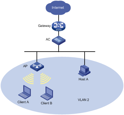
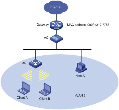
As shown in Figure 12, when VLAN-based user isolation is disabled on the AC, wireless clients A and B, and wired PC Host A in VLAN 2 can access each other directly, and can also access the Internet.
Figure 12 VLAN-based user isolation network diagram
With VLAN-based user isolation
When VLAN-based user isolation is enabled on the AC, Client A, Client B, and Host A in VLAN 2 access the Internet through the gateway.
· If you add only the MAC address of the gateway to the permitted MAC address list, Client A, Client B, and Host A in the same VLAN are isolated at Layer-2.
· If you add only the MAC address of a client (Client A, for example) to the permitted MAC address list, Client A and Client B can access each other directly, but Client B and Host A cannot.
· To enable all the clients in the VLAN to access one another at Layer-2, you must add the MAC address of the gateway and the MAC addresses of the clients to the permitted MAC address list.
Configuring VLAN-based user isolation
|
Step |
Command |
Remarks |
|
1. Enter system view. |
system-view |
N/A |
|
2. Enable user isolation for the specified VLANs. |
user-isolation vlan vlan-list enable |
By default, user isolation is disabled. |
|
3. Specify permitted MAC addresses for the specified VLANs. |
user-isolation vlan vlan-list permit-mac mac-list |
Optional. Up to 16 permitted MAC addresses can be configured for a VLAN. |
|
|
NOTE: · To avoid network disruption caused by user isolation, H3C recommends that you add the MAC address of the gateway to the permitted MAC address list and then enable user isolation. · If you configure user isolation for a super VLAN, the configuration does not take effect on the sub-VLANs in the super VLAN, and you must configure user isolation on the sub-VLANs if needed. Support for super VLAN depends on the device model. For more information, see "About the WX Series Access Controllers Configuration Guides." |
Introduction to SSID-based user isolation
SSID-based user isolation disables wireless users that use the same SSID from accessing each other at Layer-2 to ensure the security of services and accounting accuracy.
Configuring SSID-based user isolation
|
Step |
Command |
Remarks |
|
1. Enter system view. |
system-view |
N/A |
|
2. Configure a service template. |
wlan service-template service-template-number { clear | crypto } |
N/A |
|
3. Enable SSID-based user isolation. |
user-isolation enable |
Optional. By default, SSID-based user isolation is disabled. |
Isolating broadcasts and multicasts from wired users to wireless users
|
Step |
Command |
Remarks |
|
1. Enter system view. |
system-view |
N/A |
|
2. Isolate broadcasts and multicasts from wired users to wireless users. |
undo user-isolation permit broadcast |
Optional. By default, broadcasts and multicasts from wired users to wireless user are not isolated, and broadcasts and multicasts from wireless users to wireless users are isolated. |
Displaying and maintaining user isolation
|
Task |
Command |
Remarks |
|
Display user isolation statistics. |
display user-isolation statistics [ vlan vlan-id ] [ | { begin | exclude | include } regular-expression ] |
Available in any view |
|
Clear user isolation statistics. |
reset user-isolation statistics [ vlan vlan-id ] |
Available in user view |
Configuring AP group for AP based access control
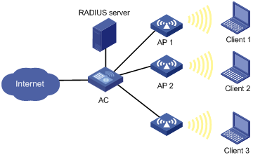
Some wireless service providers need to control the access positions of clients. For example, as shown in Figure 13, to meet security or billing needs, connect wireless clients 1, 2 and 3 to the wired network through APs 1, 2 and 3 respectively. To achieve this, you can configure an AP group and then apply the AP group in a user profile.
Figure 13 Client access control
Configuring an AP group
|
Step |
Command |
Remarks |
|
1. Enter system view. |
system-view |
N/A |
|
2. Create an AP group and enter AP group view. |
wlan ap-group value |
N/A |
|
3. Add specified APs into the AP group. |
ap template-name-list |
No AP is added by default. You can use this command repeatedly to add multiple APs, or add up to 10 APs in one command line. A nonexistent AP can be added. |
|
4. Configure a description for the AP group. |
description string |
Optional. By default, no description is configured for the AP group. |
Applying the AP group in a user profile
|
Step |
Command |
Remarks |
|
1. Enter system view. |
system-view |
N/A |
|
2. Enter user profile view. |
user-profile profile-name |
If the user profile does not exist, you need to create it first. |
|
3. Apply the AP group in the user profile. |
wlan permit-ap-group value |
No AP group is applied in the user profile by default. |
|
4. Return to system view. |
quit |
N/A |
|
5. Enable the user profile. |
user-profile profile-name enable |
Not enabled by default. Note that: The name of the user profile must be identical to that of the external group on the RADIUS server. To support roaming, all ACs in a mobility group must have the same profile name configured. |
|
|
NOTE: For more information about user profile, see Security Configuration Guide. |
Displaying and maintaining AP group
|
Command |
Remarks |
|
|
Display AP group information. |
display wlan ap-group [ group-id ] [ | { begin | exclude | include } regular-expression ] |
Available in any view |
Configuring SSID-based access control
When a user wants to access a WLAN temporarily, the administrator can specify a permitted SSID in the corresponding user profile so that the user can access the WLAN only through the SSID.
After completing the configuration, the user profile needs to be enabled to take effect.
To specify a permitted SSID:
|
Step |
Command |
Remarks |
|
|
1. Enter system view. |
system-view |
N/A |
|
|
2. Enter user profile view. |
user-profile profile-name |
If the specified user profile does not exist, this command will create it and enter its view. |
|
|
3. Specify a permitted SSID. |
wlan permit-ssid ssid-name |
No permitted SSID is specified by default, and users can access the WLAN without SSID limitation. |
|
|
4. Return to system view. |
quit |
N/A |
|
|
5. Enable the user profile. |
user-profile profile-name enable |
Not enabled by default. |
|
|
|
NOTE: · For more information about user access control, see Security Configuration Guide. · For more information about user profile, see Security Configuration Guide. |
Configuring uplink detection
Configuring uplink detection
Uplink detection ensures that when the uplink of an AC fails, clients can access external networks through APs connected to another AC whose uplink operates properly.
As shown in Figure 14, when the uplink of the AC fails, the uplink detection function can detect the failure and disable the radio on the AP. If the uplink recovers, the AC enables the radio on the AP. To achieve this purpose, you need to configure collaboration between NQA, track, and uplink detection:
· When the track entry is in Positive state, the AC enables the radio of the AP. Wireless clients can associate with the AP.
· When the track entry is in Negative state, the AC disables the radio of the AP. Wireless clients cannot associate with the AP.
· When the track entry is in Invalid state, the AC does not change the radio state of the AP.
Figure 14 Uplink detection network diagram
To configure uplink detection:
|
Step |
Command |
Remarks |
|
1. Enter system view. |
system-view |
N/A |
|
2. Specify a track entry to detect whether the uplink is reachable. |
wlan uplink track track-entry-number |
Optional. By default, no track entry is specified. |
|
|
NOTE: · For more information about the track module, see High Availability Configuration Guide. · For more information about NQA, see Network Management and Monitoring Configuration Guide. |
Configuring AC hot backup
|
|
NOTE: · Support for this feature depends on your device model. For more information, see About the WX Series Access Controllers Configuration Guides. · For the EWPX2WCMD0, LSRM1WCM3A1, and LSQM1WCMD0 cards, make sure the Ten-GigabitEthernet1/0/1 interface is up and configure the interface to permit packets from the VLAN with the hot-backup vlan vlan-id command. |
As shown in Figure 15, two ACs in a Layer 2 network provide redundancy for the APs. Each AP establishes a tunnel with each AC. The AC working in master mode provides services to all the APs in the network and the subordinate AC acts as the backup AC. A heartbeat mechanism is used between ACs to make sure failure of the master will be detected quickly by the backup AC. If the master AC fails, APs will quickly use the services provided by the subordinate AC.
Figure 15 Dual link connections
In Figure 15, AC 1 is working in master mode and providing services to AP 1, AP 2, AP 3 and AP 4. AC 2 is working in subordinate mode. APs are connected to AC 2 through subordinate tunnels. AC 1 and AC 2 are configured as backup for each other and start master/subordinate detection. When AC 2 detects AC 1 is down, AC 2 will convert the work mode from subordinate to master. All APs which are connected to AC 2 through subordinate tunnels will transform the tunnels to master tunnels and use AC 2 as the master AC.
Enabling AC hot backup
You can set the domain to which an AC belongs (a domain is a group of ACs that back up each other).
To enable AC hot backup:
|
Step |
Command |
Remarks |
|
1. Enter system view. |
system-view |
N/A |
|
2. Enable AC hot backup. |
hot-backup enable [ domain domain-id ] * |
Disabled by default. |
Configuring the VLAN ID of the port connected to the other AC
You can set the ID of the VLAN to which the port connected to another AC belongs.
To configure the VLAN ID of the port connected to another AC:
|
Step |
Command |
Remarks |
|
1. Enter system view. |
system-view |
N/A |
|
2. Configure the VLAN ID of the port connected to another AC. |
hot-backup vlan vlan-id |
By default, the port connected to another AC belongs to VLAN 1. |
Configuring the interval for sending heartbeat messages
If the master AC or backup AC does not receive any heartbeat packets from the peer within three heartbeat intervals, it considers the peer device disconnected.
To configure the interval for sending heartbeat messages:
|
Step |
Command |
Remarks |
|
1. Enter system view. |
system-view |
N/A |
|
2. Configure the interval for sending heartbeat messages. |
hot-backup hellointerval hellointerval |
2000 milliseconds by default. |
Configuring the delay for the AP to switch from the master AC to the backup AC
|
Step |
Command |
Remarks |
|
1. Enter system view. |
system-view |
N/A |
|
2. Configure the delay for the AP to switch from the master AC to the backup AC. |
wlan backup-ac switch-delay time |
The default is five seconds. |
Displaying the AC connection state
|
Task |
Command |
Remarks |
|
Display the AC connection state. |
display hot-backup state |
Available in any view |
WLAN service configuration examples
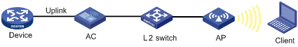
WLAN service configuration example
Network requirements
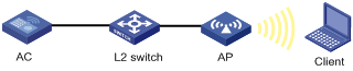
As shown in Figure 16, enable the client to access the internal network resources at any time. More specifically:
· The AP is connected to the AC through a Layer 2 switch. The manually input serial ID of the AP is 210235A29G007C000020.
· The AP provides plain-text wireless access service with SSID service1.
· The AP adopts 802.11g.

Configuration procedure
1. Configure the AC:
# Enable WLAN service, which is enabled by default.
<AC> system-view
[AC] wlan enable
# Create a WLAN ESS interface.
<AC> system-view
[AC] interface WLAN-ESS 1
[AC-WLAN-ESS1] quit
# Create a clear-type WLAN service template, configure the SSID of the service template as service and bind the WLAN-ESS interface to this service template.
[AC] wlan service-template 1 clear
[AC-wlan-st-1] ssid service
[AC-wlan-st-1] bind WLAN-ESS 1
[AC-wlan-st-1] authentication-method open-system
[AC-wlan-st-1] client max-count 10
[AC-wlan-st-1] service-template enable
[AC-wlan-st-1] quit
# Configure a radio policy (the default radio policy default_rp will be used if you don't want to configure a new radio policy for customizing related parameters).
[AC] wlan radio-policy radpolicy1
[AC-wlan-rp-radpolicy1] beacon-interval 200
[AC-wlan-rp-radpolicy1] dtim 4
[AC-wlan-rp-radpolicy1] rts-threshold 2300
[AC-wlan-rp-radpolicy1] fragment-threshold 2200
[AC-wlan-rp-radpolicy1] short-retry threshold 6
[AC-wlan-rp-radpolicy1] long-retry threshold 5
[AC-wlan-rp-radpolicy1] max-rx-duration 500
# Create an AP template named ap1 and its model is WA2100, and configure the serial ID of the AP as 210235A29G007C000020.
[AC] wlan ap ap1 model WA2100
[AC-wlan-ap-ap1] serial-id 210235A29G007C000020
[AC-wlan-ap-ap1] description L3Office
# Specify the radio type as 802.11g, and channel as 11.
[AC-wlan-ap-ap1] radio 1 type dot11g
[AC-wlan-ap-ap1-radio-1] channel 11
# Bind radio policy radiopolicy1 to radio 1, and bind service template 1 to radio 1.
[AC-wlan-ap-ap1-radio-1] radio-policy radiopolicy1
[AC-wlan-ap-ap1-radio-1] service-template 1
[AC-wlan-ap-ap1-radio-1] radio enable
2. Verify the configuration:
¡ The clients can associate with the APs and then access the WLAN.
¡ You can use the display wlan client command to view the online clients.
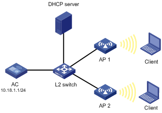
WLAN auto-AP configuration example
Network requirements
As shown in Figure 17, an AC is connected to a Layer 2 switch. AP 1 (serial ID SZ001) and AP 2 (serial ID SZ002) are connected to the AC through the L2 switch. AP1, AP 2 and the AC are in the same network. AP 1 and AP 2 get their IP address from the DHCP server. Enable the auto-AP function to enable APs to automatically connect to the AC.
Configuration procedure
1. Configure the AC:
# Create a WLAN ESS interface.
<AC> system-view
[AC] interface WLAN-ESS 1
[AC-WLAN-ESS1] quit
# Define a WLAN service template of clear type, configure its SSID as service, and bind the WLAN-ESS interface to this service template.
[AC] wlan service-template 1 clear
[AC-wlan-st-1] ssid service
[AC-wlan-st-1] bind WLAN-ESS 1
[AC-wlan-st-1] authentication-method open-system
[AC-wlan-st-1] service-template enable
[AC-wlan-st-1] quit
# Configure a radio policy (the default radio policy default_rp will be used if you don't want to configure a new radio policy for customizing related parameters).
[AC] wlan radio-policy radpolicy1
[AC-wlan-rp-radpolicy1] beacon-interval 200
[AC-wlan-rp-radpolicy1] dtim 4
[AC-wlan-rp-radpolicy1] rts-threshold 2300
[AC-wlan-rp-radpolicy1] fragment-threshold 2200
[AC-wlan-rp-radpolicy1] short-retry threshold 6
[AC-wlan-rp-radpolicy1] long-retry threshold 5
[AC-wlan-rp-radpolicy1] max-rx-duration 500
[AC-wlan-rp-radpolicy1] quit
# Configure the AP auto configuration feature.
[AC] wlan auto-ap enable
# Configure a common AP for model WA2100 (For each AP model, one common auto AP configuration is required).
[AC] wlan ap ap1 model WA2100
[AC-wlan-ap-ap1] serial-id auto
# Configure the radio of the common AP, set the maximum power to 10, and automatic channel is adopted by default.
[AC-wlan-ap-ap1] radio 1 type dot11a
[AC-wlan-ap-ap1-radio-1] max-power 10
# Bind radio policy radiopolicy1 to radio 1, and bind service template 1 to radio 1.
[AC-wlan-ap-ap1-radio-1] radio-policy radiopolicy1
[AC-wlan-ap-ap1-radio-1] service-template 1
[AC-wlan-ap-ap1-radio-1] radio enable
2. Verify the configuration:
¡ You can use the display wlan ap command to view the two APs, and can use the wlan auto-ap persistent command to convert the two auto APs to configured APs.
¡ The clients can associate with the APs and access the WLAN.
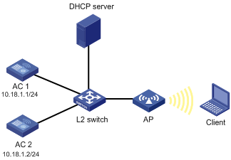
AC-AP tunnel dual-link configuration example
Network requirements
As shown in Figure 18, AC 1 and AC 2 are connected to a L2 switch. An AP is connected to AC 1 and AC 2 through the L2 switch. AC 1, AC 2 and the AP are in the same network. The AP gets its IP address from the DHCP server. The IP address of AC1 is 10.18.1.1 and the IP address of AC 2 is 10.18.1.2. AC 1 is working in master mode and AC2 is working in subordinate mode. When AC 2 detects AC 1 is down, AC 2 will convert its work mode from subordinate to master. The AP which is connected to AC 2 through a subordinate tunnel will transform the tunnel mode to master and use AC 2 as the master AC.
Configuration procedure
1. Configure AC 1:
# Create a WLAN ESS interface.
<AC1> system-view
[AC1] interface WLAN-ESS 1
[AC1-WLAN-ESS1] quit
# Define a WLAN service template of clear type, configure the SSID of the service template as service, and bind the WLAN-ESS interface to this service template.
[AC1] wlan service-template 1 clear
[AC1-wlan-st-1] ssid service
[AC1-wlan-st-1] bind WLAN-ESS 1
[AC1-wlan-st-1] authentication-method open-system
[AC1-wlan-st-1] service-template enable
[AC1-wlan-st-1] quit
# Specify the backup AC address.
[AC1] wlan backup-ac ip 10.18.1.2
# Configure the AP on AC 1.
[AC1] wlan ap ap1 model WA2100
[AC1-wlan-ap-ap1] serial-id 210235A29G007C000020
[AC1-wlan-ap-ap1] radio 1 type dot11g
[AC1-wlan-ap-ap1-radio-1] service-template 1
[AC1-wlan-ap-ap1-radio-1] radio enable
2. Configure AC 2:
# Create a WLAN ESS interface.
<AC2> system-view
[AC2] interface wlan-ess 1
[AC2-WLAN-ESS1] quit
# Define a WLAN service template of clear type, configure the SSID on AC 2 as service because the SSIDs of the master AC and subordinate AC must be the same, and bind the WLAN-ESS interface to this service template.
[AC2] wlan service-template 1 clear
[AC2-wlan-st-1] ssid service
[AC2-wlan-st-1] bind WLAN-ESS 1
[AC2-wlan-st-1] authentication-method open-system
[AC2-wlan-st-1] service-template enable
[AC2-wlan-st-1] quit
# Specify the backup AC address.
[AC2] wlan backup-ac ip 10.18.1.1
# Configure the AP on AC 2.
[AC2] wlan ap ap1 model WA2100
[AC2-wlan-ap-ap1] serial-id 210235A29G007C000020
[AC2-wlan-ap-ap1] radio 1 type dot11g
[AC2-wlan-ap-ap1-radio-1] service-template 1
[AC2-wlan-ap-ap1-radio-1] radio enable
3. Verify the configuration:
When AC 1 fails, AC 2 becomes the master AC immediately. You can use the display wlan ap command on the AC to view the status of the APs.
Configuration example for CAPWAP tunnel encryption with IPsec
Network requirements
· The data and control packets between AP 1 and AC are transmitted in plain text.
· Use IPsec to encrypt the CAPWAP control tunnel between AP 2 and the AC.
· Use IPsec to encrypt the CAPWAP control and data tunnels between AP 3 and the AC.
Figure 19 Network diagram
Configuration procedure
Establish CAPWAP connections between AP 2, AP 3, and the AC before you configure AP 2 and AP 3 provision and make sure AP 2 and AP 3 are in Run state.
# Create AP 2 and enter AP configuration view, configure the AP to use IPsec key 12345 to encrypt the control tunnel, and save the configuration to the wlan_ap_cfg.wcfg file of the AP.
<AC> system-view
[AC] wlan ap ap2 model WA2620E-AGN
[AC-wlan-ap-ap2] provision
[AC-wlan-ap-ap2-prvs] tunnel encryption ipsec pre-shared-key simple 12345
[AC-wlan-ap-ap2-prvs] save wlan ap provision name ap2
[AC-wlan-ap-ap2-prvs] quit
[AC-wlan-ap-ap2] quit
# Create AP 3 and enter AP configuration view, configure the AP to use IPsec key abcde to encrypt the control and data tunnels, and save the configuration to the wlan_ap_cfg.wcfg file of the AP.
[AC] wlan ap ap3 model WA2620E-AGN
[AC-wlan-ap-ap3] provision
[AC-wlan-ap-ap3-prvs] tunnel encryption ipsec pre-shared-key simple abcde
[AC-wlan-ap-ap3-prvs] data-tunnel encryption enable
[AC-wlan-ap-ap3-prvs] save wlan ap provision name ap3
[AC-wlan-ap-ap3-prvs] return
# Reboot AP 2 and AP 3 to validate the configuration.
<AC> reset wlan ap name ap2
<AC> reset wlan ap name ap3
# Configure an IPsec security proposal.
<AC> system-view
[AC] ipsec transform-set tran1
[AC-ipsec-transform-set-tran1] encapsulation-mode tunnel
[AC-ipsec-transform-set-tran1] transform esp
[AC-ipsec-transform-set-tran1] esp encryption-algorithm des
[AC-ipsec-transform-set-tran1] esp authentication-algorithm sha1
[AC-ipsec-transform-set-tran1] quit
# Create a DPD name dpd.
[AC] ike dpd dpd
# Set the ISAKMP SA keepalive interval to 100 seconds.
[AC] ike sa keepalive-timer interval 100
# Set the ISAKMP SA keepalive timeout to 300 seconds.
[AC] ike sa keepalive-timer timeout 300
# Enable invalid SPI recovery.
[AC] ipsec invalid-spi-recovery enable
# Configure IKE peer ap2, configure the pre-shared key 12345 (the same as that on AP 2), and apply a DPD detector to AP 2.
[AC] ike peer ap2
[AC-ike-peer-ap2] remote-address 10.1.1.3
[AC-ike-peer-ap2] pre-shared-key 12345
[AC-ike-peer-ap2] dpd dpd
[AC-ike-peer-ap2] quit
# Configure IKE peer ap3, configure the pre-shared key abcde (the same as that on AP 3), and apply a DPD detector to AP 3.
[AC] ike peer ap3
[AC-ike-peer-ap3] remote-address 10.1.1.4
[AC-ike-peer-ap3] pre-shared-key abcde
[AC-ike-peer-ap3] dpd dpd
[AC-ike-peer-ap3] quit
# Create an IPsec policy template with the name pt and the sequence number 1, and configure the IPsec policy to reference IPsec transform set tran1 and IKE peer ap2.
[AC] ipsec policy-template pt 1
[AC-ipsec-policy-template-pt-1] transform-set tran1
[AC-ipsec-policy-template-pt-1] ike-peer ap2
[AC-ipsec-policy-template-pt-1] quit
# Create an IPsec policy template with the name pt and the sequence number 2, and configure the IPsec policy to reference IPsec transform set tran1 and IKE peer ap3.
[AC] ipsec policy-template pt 2
[AC-ipsec-policy-template-pt-2] transform-set tran1
[AC-ipsec-policy-template-pt-2] ike-peer ap3
[AC-ipsec-policy-template-pt-2] quit
# Reference IPsec policy template pt to create an IPsec policy with the name map and sequence number 1.
[AC] ipsec policy map 1 isakmp template pt
# Apply the IPsec policy to VLAN-interface 1. CAPWAP tunnel establishment between AP 1 and the AC is not affected by this configuration.
[AC] interface vlan-interface 1
[AC-Vlan-interface-1] ip address 10.1.1.1 24
[AC-Vlan-interface-1] ipsec policy map
Verifying the configuration
Take AP 2 as an example. If Join requests are transmitted between AP 2 and the AC, IKE is triggered to establish SAs. You can use the display ipsec sa command to display the established SAs. After SAs are successfully established, the control packets between AP 2 and the AC are transmitted in cipher text.
Example for configuring fit APs on an AC
Configure settings for AP 1 and AP 2 on an AC so that the AC automatically assigns the settings to the fit APs over AC-AP tunnel connections. Specify the IP addresses of AP 1 and AP 2 as 1.1.1.1/24 and 1.1.1.2/24. AP 1 and AP 2 can discover AC 1 with the IP address 2.2.2.1/24.
Figure 20 Network diagram
Configuration procedure
|
|
NOTE: · An AC can assign settings only to fit APs that have established an AC-AP tunnel connection with it, so make sure AP 1 and AP 2 are in Run state. · The management VLAN of the AP must be VLAN 1. |
1. Configure the AC:
# Specify the global IP address for AC 1 so that AP 1 and AP 2 can discover AC 1.
<AC> system-view
[AC] wlan ap-provision ac ip 2.2.2.1
# Create and enter AP 1 configuration view. Configure the IP address of the management VLAN interface of AP 1 as 1.1.1.1.
[AC] wlan ap ap1 model WA2100
[AC-wlan-ap-ap1] provision
[AC-wlan-ap-ap1-prvs] ip address 1.1.1.1 24
[AC-wlan-ap-ap1-prvs] quit
[AC-wlan-ap-ap1] quit
# Create and enter AP 2 configuration view, and configure the IP address of the management VLAN interface of AP 2 as 1.1.1.2.
[AC] wlan ap ap2 model WA2210-AG
[AC-wlan-ap-ap2] provision
[AC-wlan-ap-ap2-prvs] ip address 1.1.1.2 24
[AC-wlan-ap-ap2-prvs] return
# Save the configuration in AP configuration view to the wlan_ap_cfg.wcfg files of the APs.
[AC-wlan-ap-ap2-prvs] save wlan ap provision all
[AC-wlan-ap-ap2-prvs] return
# Reboot AP 1 and AP 2 to validate the configuration.
<AC> reset wlan ap name ap1
<AC> reset wlan ap name ap2
2. Configure AC 1:
# Create a WLAN ESS interface.
<AC1> system-view
[AC1] interface wlan-ess 1
[AC1-WLAN-ESS1] quit
# Define a WLAN service template of clear type, configure its SSID as service, and bind the WLAN-ESS interface to this service template.
[AC] wlan service-template 1 clear
[AC1-wlan-st-1] ssid service
[AC1-wlan-st-1] bind wlan-ess 1
[AC1-wlan-st-1] authentication-method open-system
[AC1-wlan-st-1] service-template enable
[AC1-wlan-st-1] quit
# Create an AP template named ap1 and its model is WA2100, and configure the serial ID of the AP as 210235A29G007C000020.
[AC1] wlan ap ap1 model WA2100
[AC1-wlan-ap-ap1] serial-id 210235A29G007C000020
[AC1-wlan-ap-ap1] description L3office
# Specify the radio type as 802.11g, and channel as 11.
[AC1-wlan-ap-ap1] radio 1 type dot11g
[AC1-wlan-ap-ap1-radio-1] channel 11
# Bind radio policy radiopolicy1 to radio 1, and bind service template 1 to radio 1.
[AC1-wlan-ap-ap1-radio-1] radio-policy radiopolicy1
[AC1-wlan-ap-ap1-radio-1] service-template 1
[AC1-wlan-ap-ap1-radio-1] radio enable
[AC1-wlan-ap-ap1-radio-1] return
Verifying the configuration
After AP 1 and AP 2 are rebooted, they can establish an AC-AP tunnel connection with AC 1.
802.11n configuration example
Network requirements
As shown in Figure 21, deploy an 802.11n network to provide high-bandwidth access for multi-media applications. The AP provides a plain-text wireless service with SSID 11nservice. 802.11gn is adopted to inter-work with existing 802.11g networks.
Configuration procedure
1. Configure the AC:
# Create a WLAN-ESS interface.
<AC> system-view
[AC] interface wlan-ess 1
[AC-WLAN-ESS1] quit
# Configure a service template of clear type, configure the SSID of the service template as 11nservice, and bind the WLAN-ESS interface with the service template.
[AC] wlan service-template 1 clear
[AC-wlan-st-1] ssid 11nservice
[AC-wlan-st-1] bind WLAN-ESS 1
[AC-wlan-st-1] authentication-method open-system
[AC-wlan-st-1] service-template enable
[AC-wlan-st-1] quit
# Configure the AP on the AC, and the AP must support 802.11n.
[AC] wlan ap ap1 model WA2610E-AGN
[AC-wlan-ap-ap1] serial-id 210235A29G007C000020
# Configure the radio of the AP to operate in 802.11gn mode.
[AC-wlan-ap-ap1] radio 1 type dot11gn
# Bind the service template to radio 1.
[AC-wlan-ap-ap1-radio-1] service-template 1
[AC-wlan-ap-ap1-radio-1] radio enable
2. Verify the configuration:
¡ The clients can associate with the APs and access the WLAN.
¡ You can use the display wlan client verbose command to view the online clients, including 802.11n clients.
User isolation configuration example
Network requirements
As shown in Figure 22, the MAC address of the gateway is 000f-e212-7788. Configure user isolation on the AC so that Client A, Client B, and Host A in VLAN 2 can access the Internet but cannot access one another directly.
Configuration procedure
1. Configure the AC:
# Configure the AP so that an AC-AP tunnel connection can be established between the AC and AP.
For how to establish an AC-AP tunnel connection, see "WLAN service configuration example." The detailed configuration steps are omitted.
# Enable user isolation for VLAN 2 so that users in VLAN 2 cannot access each other directly.
<AC> system-view
[AC] user-isolation vlan 2 enable
# Add the MAC address of the gateway to the permitted MAC address list of VLAN 2 so that Client A, Client B and Host A in VLAN 2 can access the Internet.
[AC] user-isolation vlan 2 permit-mac 000f-e212-7788
2. Verify the configuration:
Client A, Client B and Host A in VLAN 2 can access the Internet, but they cannot access one another.
Uplink detection configuration example
Network requirements
As shown in Figure 23, when the uplink of the AC fails, clients cannot access external networks if they are associated with the AP connected to the AC. Enable the uplink detection function so that when the uplink of the AC fails, clients are disabled from associating with the AP connected to the AC.
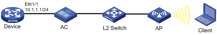
Configuration procedure
# Create an NQA test group with test type ICMP echo, and configure related test parameters.
<AC> system-view
[AC] nqa entry admin test
[AC-nqa-admin-test] type icmp-echo
[AC-nqa-admin-test-icmp-echo] destination ip 10.1.1.1
# Configure optional parameter frequency.
[AC-nqa-admin-test-icmp-echo] frequency 1000
# Configure reaction entry 1, specifying that five consecutive probe failures trigger the collaboration between the reaction entry and NQA.
[AC-nqa-admin-test-icmp-echo] reaction 1 checked-element probe-fail threshold-type consecutive 5 action-type trigger-only
[AC-nqa-admin-test-icmp-echo] quit
# Start the ICMP echo test.
[AC] nqa schedule admin test start-time now lifetime forever
# Configure track entry 1, and associate it with reaction entry 1 of the NQA test group (with the administrator admin, and the operation tag test).
[AC] track 1 nqa entry admin test reaction 1
# Specify track entry 1 for uplink detection.
[AC] wlan uplink track 1
AP group configuration examples
AP group configuration without roaming
Network requirements
As shown in Figure 24, configure an AP group and apply it in a user profile on the AC, so that a client can access the WLAN only through AP 1.
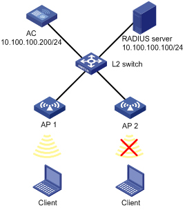
Configuration procedure
1. Configure the AC:
# Enable port security.
<AC> system-view
[AC] port-security enable
# Enable EAP authentication mode.
[AC] dot1x authentication-method eap
# Create a RADIUS scheme.
[AC] radius scheme wlan-user-policy
# Specify the RADIUS server and keys for authentication and accounting.
[AC-radius-wlan-user-policy] server-type extended
[AC-radius-wlan-user-policy] primary authentication 10.100.100.100
[AC-radius-wlan-user-policy] primary accounting 10.100.100.100
[AC-radius-wlan-user-policy] key authentication wlan
[AC-radius-wlan-user-policy] key accounting wlan
# Specify the IP address of the AC.
[AC-radius-wlan-user-policy] nas-ip 10.100.100.200
[AC-radius-wlan-user-policy] quit
# Configure an ISP domain named universal by referencing the configured RADIUS scheme.
[AC] domain universal
[AC-isp-universal] authentication default radius-scheme wlan-user-policy
[AC-isp-universal] authorization default radius-scheme wlan-user-policy
[AC-isp-universal] accounting default radius-scheme wlan-user-policy
[AC-isp-universal] quit
# Configure domain universal as the default domain.
[AC] domain default enable universal
# Configure port security on interface WLAN-ESS 1.
[AC] interface wlan-ess 1
[AC-WLAN-ESS1] port-security port-mode userlogin-secure-ext
[AC-WLAN-ESS1] port-security tx-key-type 11key
[AC-WLAN-ESS1] undo dot1x multicast-trigger
[AC-WLAN-ESS1] undo dot1x handshake
[AC-WLAN-ESS1] quit
# Configure a service template.
[AC] wlan service-template 1 crypto
[AC-wlan-st-1] ssid test
[AC-wlan-st-1] bind wlan-ess 1
[AC-wlan-st-1] authentication-method open-system
[AC-wlan-st-1] cipher-suite ccmp
[AC-wlan-st-1] security-ie rsn
[AC-wlan-st-1] service-template enable
[AC-wlan-st-1] quit
# Configure AP1.
[AC] wlan ap ap1 model wa2100
[AC-wlan-ap-ap1] serial-id 210235A29G007C000020
[AC-wlan-ap-ap1] radio 1 type dot11g
[AC-wlan-ap-ap1-radio1] service-template 1
[AC-wlan-ap-ap1-radio1] radio enable
[AC-wlan-ap-ap1-radio1] return
# Add AP1 to AP group 11, apply the AP group to user profile management and enable the user profile.
<AC> system-view
[AC] wlan ap-group 11
[AC-ap-group11] ap ap1
[AC-ap-group11] quit
[AC] user-profile management
[AC-user-profile-management] wlan permit-ap-group 11
[AC-user-profile-management] quit
[AC] user-profile management enable
2. Configure the RADIUS server:
# Deploy the user profile on the RADIUS server.
Log in to IMC, and click the Service tab. Select User Access Manager/Service Configuration from the navigation tree. Then click Add on the page to enter the following configuration page. Deploy the user profile management on the page.
Figure 25 Deploy the user profile
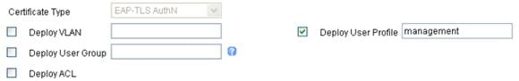
3. Verify the configuration:
The AP group in the user profile contains only AP 1, so a client can only access the WLAN through AP 1.
AP group configuration for inter-AC roaming
Network requirements
As shown in Figure 26, AC 1 and AC 2 belong to the same mobility group. Configure an AP group on the ACs so that a client can still access the WLAN when it moves from between APs.
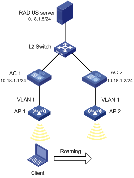
Configuration procedure
|
|
NOTE: Configuration on the RADIUS server is similar with that in AP group configuration without roaming and is omitted. |
1. Configure AC 1:
# Enable port security.
<AC1> system-view
[AC1] port-security enable
# Enable EAP authentication mode.
[AC1] dot1x authentication-method eap
# Configure port security on interface WLAN-ESS 1.
[AC1] interface wlan-ess 1
[AC1-WLAN-ESS1] port-security port-mode userlogin-secure-ext
[AC1-WLAN-ESS1] port-security tx-key-type 11key
[AC1-WLAN-ESS1] undo dot1x multicast-trigger
[AC1-WLAN-ESS1] undo dot1x handshake
[AC1-WLAN-ESS1] quit
# Define a crypto type WLAN service template, configure the SSID as abc, and bind the WLAN-ESS interface to this service template.
[AC1] wlan service-template 1 crypto
[AC1-wlan-st-1] ssid abc
[AC1-wlan-st-1] bind wlan-ess 1
[AC1-wlan-st-1] authentication-method open-system
[AC1-wlan-st-1] cipher-suite ccmp
[AC1-wlan-st-1] security-ie rsn
[AC1-wlan-st-1] service-template enable
[AC1-wlan-st-1] quit
# Create an AP template named ap1, and specify its model as WA2100, and serial ID as 210235A045B05B1236548.
[AC1] wlan ap ap1 model WA2100
[AC1-wlan-ap-ap1] serial-id 210235A045B05B1236548
[AC1-wlan-ap-ap1] radio 1 type dot11g
# Bind service template 1 to radio 1.
[AC1-wlan-ap-ap1-radio-1] service-template 1
[AC1-wlan-ap-ap1-radio-1] radio enable
[AC1-wlan-ap-ap1-radio-1] quit
[AC1-wlan-ap-ap1] quit
# Configure mobility group abc and enable the mobility group.
[AC1] wlan mobility-group abc
[AC1-wlan-mg-abc] source ip 10.18.1.1
[AC1-wlan-mg-abc] member ip 10.18.1.2
[AC1-wlan-mg-abc] mobility-group enable
[AC1-wlan-mg-abc] return
# Configure AP group 1, add AP 1 and AP 2 in it, apply it in user profile management, and enable the user profile.
<AC1> system-view
[AC1] wlan ap-group 1
[AC1-ap-group1] ap ap1 ap2
[AC1-ap-group1] quit
[AC1] user-profile management
[AC1-user-profile-management] wlan permit-ap-group 1
[AC1-user-profile-management] quit
[AC1] user-profile management enable
2. Configure AC 2:
# Enable port security.
<AC2> system-view
[AC2] port-security enable
# Enable EAP authentication mode.
[AC2] dot1x authentication-method eap
# Configure port security on interface WLAN-ESS 1.
[AC2] interface wlan-ess 1
[AC2-WLAN-ESS1] port-security port-mode userlogin-secure-ext
[AC2-WLAN-ESS1] port-security tx-key-type 11key
[AC2-WLAN-ESS1] undo dot1x multicast-trigger
[AC2-WLAN-ESS1] undo dot1x handshake
[AC2-WLAN-ESS1] quit
# Define a crypto type WLAN service template, configure the SSID as abc, and bind the WLAN-ESS interface to this service template.
[AC2] wlan service-template 1 crypto
[AC2-wlan-st-1] ssid abc
[AC2-wlan-st-1] bind wlan-ess 1
[AC2-wlan-st-1] authentication-method open-system
[AC2-wlan-st-1] cipher-suite ccmp
[AC2-wlan-st-1] security-ie rsn
[AC2-wlan-st-1] service-template enable
[AC2-wlan-st-1] quit
# Create an AP template named ap2, and specify its model as WA2100, and serial ID as 210235A22W0076000103.
[AC2] wlan ap ap2 model WA2100
[AC2-wlan-ap-ap2] serial-id 210235A22W0076000103
[AC2-wlan-ap-ap2] radio 1 type dot11g
[AC2-wlan-ap-ap2-radio-1] service-template 1
[AC2-wlan-ap-ap2-radio-1] radio enable
[AC2-wlan-ap-ap2-radio-1] quit
[AC2-wlan-ap-ap2] quit
# Configure mobility group abc and enable the mobility group.
[AC2] wlan mobility-group abc
[AC2-wlan-mg-abc] source ip 10.18.1.2
[AC2-wlan-mg-abc] member ip 10.18.1.1
[AC2-wlan-mg-abc] mobility-group enable
[AC2-wlan-mg-abc] quit
# Configure AP group 1, add AP 1 and AP 2 in it, apply it in user profile management, and enable the user profile.
[AC2] wlan ap-group 1
[AC2-ap-group1] ap ap1 ap2
[AC2-ap-group1] quit
[AC2] user-profile management
[AC2-user-profile-management] wlan permit-ap-group 1
[AC2-user-profile-management] quit
[AC2] user-profile management enable
3. Verify the configuration:
AP 1 and AP 2 are permitted in the AP group, so a client can roam between them.