- Table of Contents
-
- 02-WLAN Configuration Guide
- 00-Preface
- 01-WLAN Interface Configuration
- 02-WLAN Service Configuration
- 03-WLAN Security Configuration
- 04-WLAN Roaming Configuration
- 05-WLAN RRM Configuration
- 06-WLAN IDS Configuration
- 07-WLAN QoS Configuration
- 08-WLAN Mesh Link Configuration
- 09-WLAN Optimization Configuration
- 10-Advanced WLAN Configuration
- Related Documents
-
| Title | Size | Download |
|---|---|---|
| 08-WLAN Mesh Link Configuration | 546.27 KB |
Contents
WLAN mesh/WDS configuration task list
Configuring mesh port security
Configuring mesh portal service
Mapping a mesh profile to the radio of an MP
Mapping an MP policy to the radio of an MP
Specifying a peer MAC address on the radio
Disabling temporary link establishment
Displaying and maintaining WLAN mesh link
WLAN mesh configuration examples
Normal WLAN mesh configuration example
Subway WLAN mesh configuration example
Troubleshooting WLAN mesh link
Authentication process not started
Configuration download failed for zeroconfig device
Configuration download failed for MP
Debug error: neither local nor remote is connected to MKD
PMKMA delete is received by MPP for MP
Introduction to WLAN mesh
A WLAN network can be used to extend or replace an existing wired LAN to provide both connectivity and mobility for wireless users. A WLAN mesh network differs from the traditional WLAN in that it allows for wireless connections between access points (APs), increasing mobility and flexibility. Moreover, multi-hop wireless links can be established between APs. From end users' perspective, a WLAN mesh network appears no different; the wireless connectivity is available, just as in a traditional WLAN.
WLAN mesh is also designed for WLAN application in subways, and complies with 802.11s draft.
Basic concepts in WLAN mesh
Figure 1 Typical WLAN mesh network
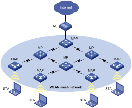
The concepts involved in WLAN mesh are described below.
|
Concept |
Description |
|
Access controller (AC) |
A device that controls and manages all the APs in the WLAN. The AC communicates with an authentication server for WLAN client authentication. |
|
Mesh point (MP) |
An IEEE 802.11 entity that contains an IEEE 802.11-conformant medium access control (MAC) and physical layer (PHY) interface to the wireless medium (WM) that supports mesh services |
|
Authenticator MP |
An MP that acts as an authenticator in forming the link between two MPs |
|
Candidate peer MP |
A neighbor MP to which a mesh link has not been established, but it meets eligibility requirements to become a peer MP. |
|
Link metric |
A criterion used to characterize the performance/quality/eligibility of a mesh link for use in a mesh path |
|
Mesh |
A network consisting of two or more mesh points which communicate with each other via mesh services |
|
Mesh access point (MAP) |
A mesh point that is collocated with one or more access points |
|
Mesh action frame |
802.11 management frame which has mesh specific action category |
|
Mesh link |
A link between two MPs |
|
Mesh portal point (MPP) |
A mesh point that is collocated with one or more portals |
|
Peer MP |
Peer MP to which the local MP has established a mesh link |
|
Selector MP |
The MP that is responsible for selecting the security parameters between two MPs |
|
Station (STA) |
A wireless terminal (a PC or laptop) with a wireless network card |
Advantages of WLAN mesh
In the current WLAN solution, APs must be interconnected by using cables, switches, routers, and power supplies, making the wireless network complex, costly, and time consuming to deploy.
The WLAN mesh technology offers a totally new approach for deploying wireless networks by allowing operators to deploy wireless networks anywhere and anytime.
WLAN mesh has the following advantages:
· Low cost and high performance
· Expandable without the need of new wiring or access points
· Easy deployment
· Applicable to areas such as metros, companies, offices, large warehouses, manufacturing plants, ports, and waterfronts
· Avoidance of single point failures because of multi-path availability
Deployment scenarios
This section covers deployment scenarios of WLAN mesh, available in two categories: one for subway networking and the other for typical networking.
Typical WLAN mesh deployment
· AC + fit MP scenario
Figure 2 Normal AC + fit MP scenario
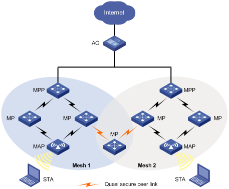
As shown in Figure 2, two mesh networks are controlled by the same AC. At least one MPP in a mesh has wired connectivity with the AC. When an MP starts up, it scans the network and forms quasi-secure connections with all available MPs in its vicinity (quasi-secure connections are temporary links with default or minimum configuration which allows the MP to connect to the AC for downloading its configurations. Only configuration-related messages are allowed to pass through the links). After downloading its configurations from the AC, the MP establishes secure connections with neighbors.
In a geographical area that has more than one mesh network deployed, when an MP starts up, it does not know through which mesh it should connect to the AC, so it forms quasi-secure links with MPs in all available mesh networks.
· One MP with two radios, each on a different mesh
Figure 3 One fit MP with two radios, each on a different mesh
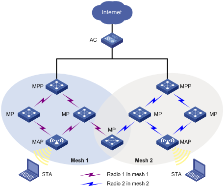
As shown in Figure 3, an MP has two radios, each of which is present in a different mesh network. The only constraint is that both meshes are managed by the same AC.
· Two mesh networks controlled by two ACs
Figure 4 Two mesh networks controlled by two ACs in the same wired network
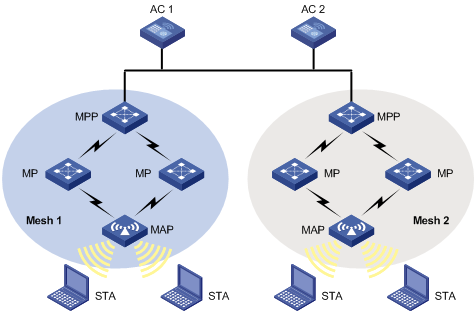
As shown in Figure 4, two mesh networks in the same geographical area are managed by different ACs, which can be in the same wired network or in different wired networks.
Subway WLAN mesh deployment
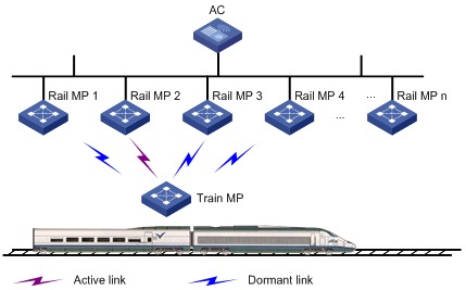
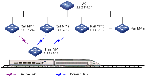
In a subway system, the control and data information must be sent to fast-moving trains in real time to provide Internet access service for customers in the trains and provide control information for train operation. As shown in Figure 5, a subway WLAN mesh solution adopts the AC + Rail MP (in fit mode) + Train MP (fat mode) networking mode. Rail MPs are deployed along the railway and connected to the AC through wired connections.
Figure 5 Subway deployment of mesh
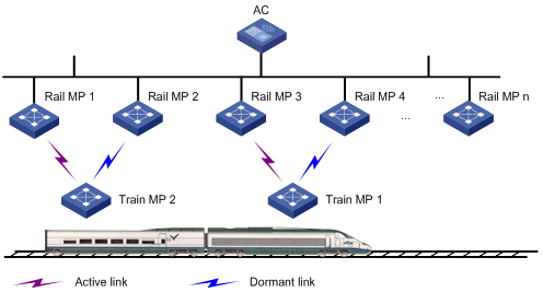
The train MPs connect to rail MPs based on the radio signal strength indicator (RSSI) values. A train MP establishes with rail MPs two types of links (active and dormant), in which, one link is the active and all the other links are dormant. Data is transferred through the active link only. The active link changes during the movement of the train MP.
The subway WLAN mesh deployment uses the Mobile Link Switch Protocol (MLSP), a proprietary protocol developed by H3C for obtaining high-speed link switch with zero packet loss during train movement. H3C has adopted new IEEE standard 802.11s as the underlying protocol for link formation and communication between mobile radio (MR) and wayside AP. Train MPs are not required to act as authenticators.
WLAN mesh security
WLAN mesh networks use airwaves as a communication medium, so they are very vulnerable to attacks. Therefore, security is an essential part of WLAN mesh networks. Security involves encryption algorithms and key distribution and management.
Mesh link metric
The metric of a mesh link is calculated based on the signal strength indication (RSSI) of the frame received from the peer MP. The metric or cost of the mesh link is used to select the best route to forward data frames.
Mobile link switch protocol
At any given time, an active link should be available between a rail MP and a train MP for data communication. MLSP was developed to create and break links during train movement.
Terminology of MLSP
As shown in Figure 6, when the train is moving, it needs to break the existing active link with rail MP 2 and create a new active link with another rail MP.
· Active Link—Logical link through which all data communication from/to a train MP happens.
· Dormant Link—Logical link over which no data transfer happens, but it satisfies all the criteria for becoming an active link.
· Proxy device—A device such as a server that is connected to a train MP for receiving traffic.
MLSP advantages
1. MLSP makes sure that the link switch time is less than 30 ms.
2. MLSP works well even if the chipset gets saturated at high power level.
3. MLSP achieves zero packet loss during link switch.
Operation of MLSP
MLSP establishes multiple links at any given time between a train MP and multiple rail MPs to provide link redundancy, ensuring high performance and good robustness for the network.
The following four parameters are considered by MLSP for link switch. Based on the deployment, all these parameters are tunable to achieve best results.
· Link formation RSSI/link hold RSSI—This is the minimum RSSI to allow a link to be formed and held. Therefore, the minimum RSSI must be ensured at any given point in the tunnel. Otherwise, the error rate can be very high.
· Link switch margin—If the RSSI of the new link is greater than that of the current active link by the link switch margin, active link switch will happen. This mechanism is used to avoid frequent link switch.
· Link hold time—An active link remains up within the link hold time, even if the link switch margin is reached. This mechanism is used to avoid frequent link switch.
· Link saturation RSSI—This is the upper limit of RSSI on the active link. If the value is reached, the chipset is saturated and link switch will happen.
Formation of dormant links
A train MP performs active scanning to find neighboring rail MPs by sending probe requests at a very high rate. Based on probe responses received, the train MP forms a neighbor table.
After that, the train MP creates dormant links with rail MPs that have an RSSI value greater than the link formation RSSI.
Selection of active link
A train MP selects the active link from dormant links based on the following rules:
1. If no dormant link is available, the active link cannot be formed.
2. Active link switch will not happen within the link hold time, except the following two conditions:
¡ Condition 1—The active link RSSI exceeds the link saturation RSSI.
¡ Condition 2—The active link RSSI is below the link hold RSSI.
3. When the link hold timer expires, if no dormant link has RSSI greater than the active link RSSI by the link switch margin, link switch will not happen.
4. In normal scenarios, active link switch will happen when all of these following conditions are met:
¡ The link hold timer expires.
¡ The dormant link's RSSI is higher than the current active link's RSSI by the link switch margin.
¡ The dormant link RSSI is not greater than the link saturation RSSI.
¡ The RSSI of the new link should be increasing.
5. Once the RSSI of the active and dormant links has gone below the link hold RSSI, links should be broken. However, to ensure service availability in worse cases, if the active link RSSI has gone below the link hold RSSI and no dormant links exist, the active link will not be broken.
Protocols and standards
· Draft P802.11s_D1.06
· ANSI/IEEE Std 802.11, 1999 Edition
· IEEE Std 802.11a
· IEEE Std 802.11b
· IEEE Std 802.11g
· IEEE Std 802.11i
· IEEE Std 802.11s
· IEEE Std 802.11-2004
· draft-ohara-capwap-lwapp-03
Introduction to WDS
Wireless distribution system (WDS) provides wireless bridging links between separate LAN segments to provide connectivity between them.
Basic concepts in WDS
The WDS feature provides a single hop wireless link between two APs, including:
· Link formation—Connections made based on the messages exchanged between two peer nodes.
· Link security—Provides PSK plus CCMP security.
Advantages of WDS
At present, 802.11 based WLAN technologies are widely applied in the home, SOHO, and enterprise scenarios.
APs are connected through cables, switches, routers and power supplies. As a result, the wireless network is complex, costly and no longer wireless, and it requires a lot time to deploy a network.
WDS provides wireless connectivity between separate LAN segments to simplify WLAN deployment.
WDS has the following advantages:
· Low cost for high performance deployment options
· Expansion availability without the need for new wiring or more access points
· Easy deployment in scenarios such as metros, companies, offices, large warehouses, manufacturing divisions, ports, and waterfronts.
Deployment scenarios
The WDS feature supports the following three topologies.
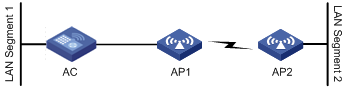
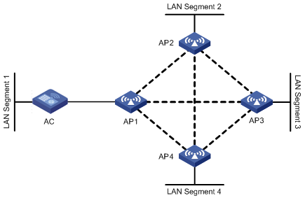
Topology 1 Peer to Peer Connection [Point to Point]: In this topology, two neighbor MPs form a bridge between two LANs. In Figure 7, AP 1 and AP 2 bridge 802.3 data between LAN segments 1 and 2 by converting it to 802.11s format and sending it over a wireless link.
Figure 7 WDS point to point topology
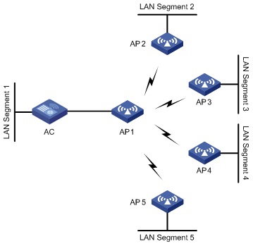
Topology 2 Centralized Bridging [Point to multipoint]: In this topology, a centralized bridging device forms wireless links with multiple MPs to bridge data among multiple LAN segments. As shown in Figure 8, data transferred between different LAN segments goes via AP 1.
Figure 8 WDS point to multipoint topology
Topology 3 (Self Topology Detection and Bridging): In this topology, MPs automatically detect neighbors and form wireless links to provide wireless connectivity between LAN segments, as shown in Figure 9.
Figure 9 Self topology detection and bridging
WLAN mesh/WDS configuration task list
Complete the following tasks to configure WLAN mesh/WDS:
|
Remarks |
|
|
Required |
|
|
Required |
|
|
Required |
|
|
Optional |
|
|
Optional |
|
|
Required |
|
|
Required |
|
|
Required |
|
|
Optional |
Configuring an MKD ID
A common MKD ID should be configured for all fat MPs to form links in between.
To configure an MKD ID:
|
Step |
Command |
Remarks |
|
1. Enter system view. |
system-view |
N/A |
|
2. Configure an MKD ID. |
wlan mkd-id mkd-id |
By default, the MKD ID is 000F-E200-0001. |
Configuring mesh port security
|
Step |
Command |
Remarks |
|
1. Enter system view. |
system-view |
N/A |
|
2. Enter WLAN mesh interface view. |
Interface wlan-mesh interface-number |
N/A |
|
3. Enable 11key negotiation. |
port-security tx-key-type 11key |
By default, 11key negotiation is disabled. |
|
4. Configure a PSK. |
port-security preshared-key { pass-phrase | raw-key } key |
By default, no PSK is configured. |
|
5. Configure the port to operate in PSK mode. |
port-security port-mode psk |
By default, the port operates in noRestrictions mode. |
|
|
NOTE: For more information about the port-security tx-key-type 11key, port-security preshared-key, and port-security port-mode commands, see Security Command Reference. |
Configuring a mesh profile
A mesh profile is created and mapped to an MP so that it can provide mesh services to other MPs that have the same mesh profile mapped.
|
Step |
Command |
Remarks |
|
1. Enter system view. |
system-view |
N/A |
|
2. Create a mesh profile and enter mesh profile view. |
wlan mesh-profile mesh-profile-number |
N/A |
|
3. Configure the mesh ID. |
mesh-id mesh-id-name |
By default, no mesh ID is set for the mesh profile. |
|
4. Bind a WLAN mesh interface. |
bind wlan-mesh interface-index |
By default, no interface is bound to the mesh profile. |
|
5. Configure the mesh link keep alive interval. |
link-keep-alive keep-alive-interval |
Optional. By default, the mesh link keep-alive interval is 2 seconds. |
|
6. Configure the backhaul radio rate. |
link-backhaul-rate rate-value |
Optional. By default, the link backhaul rate is 18 Mbps. |
|
7. Enable the mesh profile. |
mesh-profile enable |
By default, the mesh profile is disabled. |
|
8. Return to system view. |
quit |
N/A |
|
9. Enable the mesh key distributor (MKD) service for the mesh profile. |
mkd-service enable mesh-profile mesh-profile-number |
By default, the MKD service is disabled. |
Configuring mesh portal service
Mesh portal service should be enabled for an MP to work as a mesh portal point (MPP).
|
|
NOTE: Enable mesh portal service only for MPPs (APs connected to the AC). |
To configure mesh portal service:
|
Step |
Command |
Remarks |
|
1. Enter system view. |
system-view |
N/A |
|
2. Create an AP template and enter AP template view. |
wlan ap ap-name [ model model-name [ id ap-id ] ] |
The model name is required only when you create a new AP template. |
|
3. Enable the portal service. |
portal-service enable |
By default, the portal service is disabled. |
Configuring an MP policy
Link formation and maintenance are driven by the attributes specified in the MP policy.
To configure an MP policy:
|
Step |
Command |
Remarks |
|
1. Enter system view. |
system-view |
N/A |
|
2. Create an MP policy and enter MP policy view. |
wlan mp-policy policy-name |
By default, the radio adopts the default MP policy default_mp_plcy that cannot be modified. |
|
3. Enable link initiation. |
link-initiation enable |
Optional. By default, link initiation is enabled. |
|
4. Configure the maximum number of links. |
link-maximum-number max-link-number |
Optional. By default, the maximum number is 2. |
|
5. Configure the link formation/link hold RSSI. |
link-hold-rssi value |
Optional. The default is 15 dBm. |
|
6. Configure the link hold time. |
link-hold-time value |
Optional. The default is 4000 milliseconds. |
|
7. Configure the link switch margin. |
link-switch-margin value |
Optional. The default is 10 dBm. |
|
8. Configure the link saturation RSSI. |
link-saturation-rssi value |
Optional. The default is 150 dBm. |
|
9. Configure the probe request interval. |
probe-request-interval interval-value |
Optional. By default, the probe request interval is 1000 ms. |
|
10. Enable MLSP. |
mlsp enable |
Optional. By default, MLSP is disabled. If MLSP is disabled on a radio, the MLSP proxy MAC address configured under the current MP policy is removed. |
|
11. Configure the MLSP proxy MAC address. |
mlsp-proxy mac-address mac-address [ vlan vlan-id ] [ ip ip-address ] |
Optional. By default, no MLSP proxy MAC address is configured. This command is visible only when MLSP is enabled. |
|
12. Enable the device to act as an authenticator based on negotiation results. |
role-authenticator enable |
Optional. By default, whether a device acts as an authenticator is based on negotiation results. |
|
13. Configure the link rate mode. |
link rate-mode { fixed | real-time } |
Optional. The default link rate mode is fixed. |
|
|
NOTE: The mlsp enable and mlsp-proxy mac-address commands are applicable to subway WLAN mesh networks only. |
Mapping a mesh profile to the radio of an MP
For an MP to advertise mesh capabilities, a mesh profile should be mapped to the radio of the MP.
To map a mesh profile to a radio:
|
Step |
Command |
Remarks |
|
1. Enter system view. |
system-view |
N/A |
|
2. Enter AP template view. |
wlan ap ap-name [ model model-name [ id ap-id ] ] |
The model name is required only when you create a new AP template. |
|
3. Enter radio view. |
radio radio-number [ type { dot11a | dot11an | dot11b | dot11g | dot11gn } ] |
N/A |
|
4. Map the mesh profile to the radio. |
mesh-profile mesh-profile-number |
By default, no mesh profile is mapped to the radio. |
Mapping an MP policy to the radio of an MP
An MP policy should be mapped to a radio so that link formation and maintenance on the radio can be driven by the attributes specified in the MP policy.
To map an MP policy to the radio of an MP (on an AC):
|
Step |
Command |
Remarks |
|
1. Enter system view. |
system-view |
N/A |
|
2. Enter AP template view. |
wlan ap ap-name [ model model-name [ id ap-id ] ] |
The model name is required only when you create a new AP template. |
|
3. Enter radio view. |
radio radio-number [ type { dot11a | dot11an | dot11b | dot11g | dot11gn } ] |
N/A |
|
4. Map the MP policy to the radio. |
mp-policy policy-name |
By default, the radio adopts the default MP policy default_mp_plcy. |
Specifying a peer MAC address on the radio
You need to specify the MAC addresses of permitted peers on the local radio interface.
To specify a peer MAC address on a radio:
|
Step |
Command |
Remarks |
|
1. Enter system view. |
system-view |
N/A |
|
2. Enter AP template view. |
wlan ap ap-name [ model model-name [ id ap-id ] ] |
The model name is required only when you create a new AP template. |
|
3. Enter radio view. |
radio radio-number [ type { dot11a | dot11an | dot11b | dot11g | dot11gn } ] |
N/A |
|
4. Specify a permitted peer and specify the cost of the mesh link to the peer. |
mesh peer-mac-address mac-address [ cost cost ] |
By default, the radio has no peer MAC address configured, all neighbors are permitted, and the cost of the mesh link to a peer is automatically calculated. |
Disabling temporary link establishment
In a subway mesh network shown in Figure 5, when a Rail MP goes offline (because of power loss, for example), it loses its configuration and tries to establish a temporary link with another Rail MP to reach the AC. You can perform this task to disable temporary link establishment on the AC so other Rail MPs will not provide AC access for the failed Rail MP. The Rail MP can reach the AC only when its wired port goes up.
To disable temporary link establishment:
|
Step |
Command |
Remarks |
|
1. Enter system view. |
system-view |
N/A |
|
2. Enter MP policy view. |
wlan mp-policy policy-name |
N/A |
|
3. Disable temporary link establishment. |
undo temporary-link enable |
By default, temporary link establishment is enabled. |
Displaying and maintaining WLAN mesh link
|
Task |
Command |
Remarks |
|
Display mesh link information. |
display wlan mesh-link ap { all | name ap-name [ verbose ] } [ | { begin | exclude | include } regular-expression ] |
Available in any view |
|
Display mesh profile information. |
display wlan mesh-profile { mesh-profile-number | all } [ | { begin | exclude | include } regular-expression ] |
Available in any view |
|
Display MP policy information. |
display wlan mp-policy { mp-policy-name | all } [ | { begin | exclude | include } regular-expression ] |
Available in any view |
|
Perform a mesh link test on the specified AP and display the test results. |
wlan mesh-link-test ap-name |
Available in user view |
WLAN mesh configuration examples
Normal WLAN mesh configuration example
Network requirements
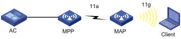
· As shown in Figure 10, establish a mesh link between the MAP and the MPP.
· Configure 802.11g on the MAP so that the client can access the network.
Configuration procedure
1. Configure Mesh:
# Enable port security.
<AC> system-view
[AC] port-security enable
# Create WLAN mesh interface 1. Enable 11key negotiation, set a PSK, and set the port security mode as PSK mode for the interface.
[AC] interface WLAN-MESH 1
[AC-WLAN-MESH1] port-security tx-key-type 11key
[AC-WLAN-MESH1] port-security preshared-key pass-phrase 12345678
[AC-WLAN-MESH1] port-security port-mode psk
[AC-WLAN-MESH1] quit
# Create mesh profile 1, and bind WLAN mesh interface 1 to it.
[AC] wlan mesh-profile 1
[AC-wlan-mshp-1] bind WLAN-MESH 1
[AC-wlan-mshp-1] quit
# Configure an MKD-ID (an MKD-ID exists by default, and you can omit this command).
[AC] wlan mkd-id 0eab-01cd-ef00
# Enable the MKD service.
[AC] mkd-service enable mesh-profile 1
# Set the mesh ID as outdoor for mesh profile 1, and enable the mesh profile.
[AC] wlan mesh-profile 1
[AC-wlan-mshp-1] mesh-id outdoor
[AC-wlan-mshp-1] mesh-profile enable
[AC-wlan-mshp-1] quit
# A default MP policy exists by default. You can also configure an MP policy. The default MP policy is used in this example.
2. Configure MPP:
# Create AP template mpp of model WA2620-AGN, and configure its serial ID.
[AC] wlan ap mpp model WA2620-agn
[AC-wlan-ap-mpp] serial-id 59235B15D114C005623
# Create radio 1, specify channel 149, map mesh profile 1 to the radio, and then enable the radio.
[AC-wlan-ap-mpp] radio 1 type dot11a
[AC-wlan-ap-mpp-radio-1] channel 149
[AC-wlan-ap-mpp-radio-1] mesh-profile 1
[AC-wlan-ap-mpp-radio-1] radio enable
[AC-wlan-ap-mpp-radio-1] quit
# Enable the mesh portal service for MPP.
[AC-wlan-ap-mpp] portal-service enable
3. Configure MAP:
# Create AP template map of model WA2620-AGN, and configure its serial ID.
[AC] wlan ap map model WA2620-agn
[AC-wlan-ap-map] serial-id 21023529G007C000020
# Create radio 1, specify channel 149 for it, and map mesh profile 1 to it, and then enable the radio.
[AC-wlan-ap-map] radio 1 type dot11a
[AC-wlan-ap-map-radio-1] channel 149
[AC-wlan-ap-map-radio-1] mesh-profile 1
[AC-wlan-ap-map-radio-1] radio enable
[AC-wlan-ap-map-radio-1] return
After the configuration, a mesh link will be established between the MAP and MPP, and they can ping each other.
4. Configure 802.11g service on the MAP so that the client can access the network.
For the related configuration, see "Configuring WLAN services."
After 802.11g is configured on the MAP, the client and the AC can ping each other, and the client can access the network through the mesh link.
Verifying the configuration
# Display the mesh link information on the AC.
<AC> display wlan mesh-link ap all
Mesh Link Information
--------------------------------------------------------------------------------
AP Name: mpp
--------------------------------------------------------------------------------
Peer Local Status RSSI Packets(Rx/Tx)
--------------------------------------------------------------------------------
00ef-2231-0b4a 00aa-4433-6699 Forwarding 50 13442/134234
--------------------------------------------------------------------------------
AP Name: map
--------------------------------------------------------------------------------
Peer Local Status RSSI Packets(Rx/Tx)
--------------------------------------------------------------------------------
00aa-4433-6699 00ef-2231-0b4a Forwarding 54 231/14234
--------------------------------------------------------------------------------
The output shows that the MPP and MAP have established a mesh link.
Subway WLAN mesh configuration example
Network requirements
Configure WLAN mesh so that the train MP will form links with rail MPs during movement, among them one link is the active link and all others are dormant links.
Configuration procedure
1. Configure AC related functions:
# Enable port security.
<AC> system-view
[AC] port-security enable
# Create WLAN mesh interface 1. Enable 11key negotiation, set a PSK, and set the port security mode as PSK mode for the interface.
[AC] interface WLAN-MESH 1
[AC-WLAN-MESH1] port-security tx-key-type 11key
[AC-WLAN-MESH1] port-security preshared-key pass-phrase 12345678
[AC-WLAN-MESH1] port-security port-mode psk
[AC-WLAN-MESH1] quit
# Create mesh profile 1, and bind WLAN mesh interface 1 to it.
[AC] wlan mesh-profile 1
[AC-wlan-mshp-1] bind WLAN-MESH 1
[AC-wlan-mshp-1] quit
# Configure an MKD-ID (The MKD-ID exists by default, and you can omit this command).
[AC] wlan mkd-id 0eab-01cd-ef00
# Enable the MKD service.
[AC] mkd-service enable mesh-profile 1
# Set the mesh ID as train for mesh profile 1, and enable the mesh profile.
[AC] wlan mesh-profile 1
[AC-wlan-mshp-1] mesh-id train
[AC-wlan-mshp-1] mesh-profile enable
[AC-wlan-mshp-1] quit
# Create MP policy rail_policy, and disable link initiation and the authenticator role.
[AC] wlan mp-policy rail_policy
[AC-wlan-mp-policy-rail_policy] undo link-initiation enable
[AC-wlan-mp-policy-rail_policy] undo role-authenticator enable
[AC-wlan-mp-policy-rail_policy] quit
# Create AP template railmpl of model WA2210X-GE, and configure its serial ID as 210235A42RB099000003.
[AC] wlan ap railmp1 model wa2210x-ge
[AC-wlan-ap-railmp1] serial-id 210235A42RB099000003
[AC-wlan-ap-railmp1] portal-sevice enable
# Create radio 1, specify channel 149, map MP policy rail_policy and mesh profile 1 to the radio, and enable the radio.
[AC-wlan-ap-railmp1] radio 1
[AC-wlan-ap-railmp1-radio-1] channel 1
[AC-wlan-ap-railmp1-radio-1] mp-policy rail_policy
[AC-wlan-ap-railmp1-radio-1] mesh-profile 1
[AC-wlan-ap-railmp1-radio-1] radio enable
[AC-wlan-ap-railmp1-radio-1] return
Configurations for other rail MPs are similar.
2. Configure train MP:
# Enable port security.
<TrainMP> system-view
[TrainMP] port-security enable
# Create WLAN mesh interface 1. Enable 11key negotiation, set a PSK, and set the port security mode as PSK mode for the interface.
[TrainMP] interface wlan-mesh 1
[TrainMP-WLAN-MESH1] port-security tx-key-type 11key
[TrainMP-WLAN-MESH1] port-security preshared-key pass-phrase 12345678
[TrainMP-WLAN-MESH1] port-security port-mode psk
[TrainMP-WLAN-MESH1] quit
# Create mesh profile 1, and bind WLAN mesh interface 1 to it.
[TrainMP] wlan mesh-profile 1
[TrainMP-wlan-mshp-1] bind wlan-mesh 1
# Set the mesh ID as train for mesh profile 1, and enable the mesh profile.
[TrainMP-wlan-mshp-1] mesh-id train
[TrainMP-wlan-mshp-1] mesh-profile enable
[TrainMP-wlan-mshp-1] quit
# Create MP policy train_policy, set the maximum number of links as 8, enable MLSP, and configure the proxy MAC address as 000f-e287-8700.
[TrainMP] wlan mp-policy train_policy
[TrainMP-wlan-mp-policy-train_policy] link-maximum-number 8
[TrainMP-wlan-mp-policy-train_policy] mlsp enable
[TrainMP-wlan-mp-policy-train_policy] mlsp-proxy mac-address 000f-e287-8700
[TrainMP-wlan-mp-policy-train_policy] quit
# Configure interface WLAN-Radio1/0/2: specify the working channel as 1, and bind MP policy train_policy and mesh profile 1.
[TrainMP] interface wlan-radio 1/0/2
[TrainMP-WLAN-Radio1/0/2] channel 1
[TrainMP-WLAN-Radio1/0/2] mp-policy train_policy
[TrainMP-WLAN-Radio1/0/2] mesh-profile 1
[TrainMP-WLAN-Radio1/0/2] return
Troubleshooting WLAN mesh link
Authentication process not started
Symptom
A PMK MA request is sent successfully for client 000F-E27C-6C00, but the authentication process is not started.
Analysis
The portal service is enabled for an MP without wired connection.
Solution
Enter AP template view and use command display this to verify if portal service is enabled. If yes, use command undo portal-service enable to disable the portal service.
Failed to ping MAP
Symptom
Ping from a station is not working through the MAP.
Analysis
The portal service is disabled and authenticator role is enabled for the MAP.
Solution
1. Enter AP template view and use command display this to verify if portal service is disabled. If yes, use command portal-service enable to enable the portal service for the MAP.
2. Enter radio view and verify if the MP policy mapped to the radio has role authenticator enabled. If yes, disable all the radios to which this MP policy is mapped.
3. Enter MP policy view and use command undo role-authenticator enable to set the device not to play the role of an authenticator.
4. Enable all the radios.
Configuration download failed for zeroconfig device
Symptom
A zero-configuration device forms links but configuration download does not happen.
Analysis
· Channel configuration may be wrong.
· The mapped mesh profile may be wrong.
Solution
1. Go to radio view and use command display this.
2. Verify that the channel must be the same as the MPP. If not, change the channel using command channel.
3. Verify that the mesh profile mapped to the radio is the same as that mapped to the MPP's radio. If not, unmap the current mesh profile using command undo mesh-profile. Then map the correct mesh profile by using command mesh-profile.
Configuration download failed for MP
Symptom
A mesh profile is mapped to the radio of an MP but configuration is not downloaded to the MP.
Analysis
· Verify that the security configuration has been made.
· Verify that the mapped mesh profile is enabled.
· Verify that the radio is enabled.
Solution
1. Configure the security parameters.
2. Enable the mapped mesh profile by using command mesh-profile enable.
3. Enable the radio by using command radio enable.
Debug error: neither local nor remote is connected to MKD
Symptom
Debug error: Neither local nor remote is connected to MKD.
Analysis
Check if MKD service is enabled for the mapped mesh profile.
Solution
Enable the MKD service for the mesh profile by using command mkd-service enable.
PMKMA delete is received by MPP for MP
Symptom
After the MPP comes up, an MP tries to connect to it. During this process, the AC will receive a number of PMKMA requests, and send back PMKMA responses. After that, PMKMA delete is sent to the MPP for the MP.
Analysis
Check if intrusion detection is enabled.
Solution
If intrusion detection is enabled, disable it.