- Table of Contents
-
- H3C Access Controllers Web-Based Configuration Guide(E3703P61 R2509P61 R3709P61 R2609P61 R3509P61)-6W103
- 00-Preface
- 01-About
- 02-Web overview
- 03-Login
- 04-Quick Start
- 05-Summary
- 06-Device
- 07-Network
- 08-AP Configuration
- 09-Wireless Service
- 10-WLAN Roaming Configuration
- 11-Radio Configuration
- 12-Authentication
- 13-Security
- 14-QoS Configuration
- 15-Advanced Settings
- 16-Stateful Failover Configuration
- 17-VPN
- 18-SSL VPN Configuration
- Related Documents
-
| Title | Size | Download |
|---|---|---|
| 15-Advanced Settings | 3.22 MB |
Configuring the AC to accept APs with a different software version
Configuring WLAN advanced settings
Setting a country/region code·
Configuring client information backup
Configuring continuous transmitting mode
Configuring a channel busy test
Configuring multicast optimization
Configuring a guest access tunnel
Configuring a Hotspot2.0 policy
Advanced settings configuration examples
1+1 fast backup configuration example
1+N backup configuration example
Client information backup configuration example
AP-based session-mode load balancing configuration example
AP-based traffic-mode load balancing configuration example
Group-based session-mode load balancing configuration example
Group-based traffic-mode load balancing configuration example
AP version upgrade configuration example
Wireless location configuration example
Wireless sniffer configuration example
AP provision configuration example
Band navigation configuration example
VLAN pool configuration example
Multicast optimization configuration example
Configuring advanced settings
Advanced settings overview
Country/Region code
Radio frequencies for countries and regions vary based on country regulations. A country/region code determines characteristics such as frequency range, channel, and transmit power level. Configure the valid country/region code for a WLAN device to meet the specific country regulations.
1+1 AC backup
Support for the 1+1 backup feature might vary depending on your device model. For more information, see "About the H3C Access Controllers Web-Based Configuration Guide."
Dual-link backup
· Dual links:
Dual links allow for AC backup. An AP establishes links with two different ACs. The active AC provides services for APs in the network, and the standby AC provides backup service for the active AC. If the active AC fails, the standby AC takes over to provide services for the APs.
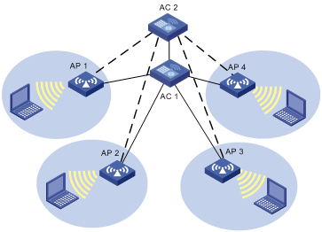
AC 1 is operating in active mode and providing services to AP 1, AP 2, AP 3, and AP 4. AC 2 is operating in standby mode. APs are connected to AC 2 through backup links. When AC 1 is down, AC 2 converts to operate in active mode even when AC 1 is up again, in which case, AC 1 is in standby mode. However, this is not so if an AC is configured as the primary AC. For more information about primary AC, see "Primary AC recovery."
· Using fast link fault detection, you can configure 1+1 fast backup (see "1+1 fast backup") to provide uninterrupted services.
Primary AC provides a mechanism to make sure the primary AC is chosen in precedence by APs as an active AC. When the primary AC goes down, the APs switch to connect to the standby AC. As soon as the active AC recovers, the APs automatically connect to the primary AC again.
Figure 2 Primary AC recovery
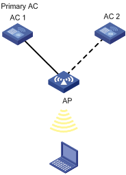
AC 1 is the primary AC with the connection priority of 7, and it establishes a connection with the AP. AC 2 acts as the secondary AC. If AC 1 goes down, AC 2 takes over to provide services to AP until AC 1 recovers. Once the primary AC is reachable again, the AP automatically establishes a connection with the primary AC. For more information about priority configuration, see "Configuring an AP connection priority."
1+1 fast backup
Fast link fault detection allows two ACs in 1+1 backup to detect the failure of each other. To achieve this, a heartbeat detection mechanism is used. When the active AC goes down, the standby AC can quickly detect the faults and become the new active AC.
|
|
NOTE: · 1+1 fast backup supports only tunnel backup between AC and AP to make sure when the main AC goes down, the standby AC can quickly connect to the AP. 1+1 fast backup does not back up client information. · Support for this feature depends on the device model. For more information, see "About the H3C Access Controllers Web-Based Configuration Guides." |
1+N AC backup
1+N AC backup allows an AC to operate as a backup for multiple ACs. The active ACs independently provide services for APs that connect to them, and only one standby AC provides backup service for the active ACs. If an active AC goes down, the APs connecting to it can detect the failure quickly and make connections to the standby AC. As soon as the active AC recovers, the APs automatically connect to the original active AC again. This makes sure the standby AC operates as a dedicated backup for the active ACs. 1+N AC backup delivers high reliability and saves network construction cost.
Client information backup
In a network environment as shown in Figure 3, to prevent clients from going offline due to unexpected primary/backup AC switchover, the ACs must support the stateful failover function. This feature enables the primary AC to send client information in real time to the backup AC through an IACTP tunnel, ensuring consistency of client information on the two ACs. When a switchover occurs, the backup AC immediately takes over services for online clients to ensure service continuity.
For stateful failover to operate correctly, configure client information backup on both the primary and backup ACs so that the client information on both ACs are identical.
This feature supports backing up information for clients that use 802.1X authentication and clients that use clear-type wireless services.

As shown in Figure 3, AC 1 and AC 2 back up each other. AC 1 is the primary AC of AP 1, AC 2 is the primary AC of AP 1, and the two ACs are in the same IACTP tunnel. When clients go online and offline or roam between the ACs, the two ACs synchronized client information in real time to ensure consistent client information.
If an anomaly occurs, for example, AC 1 fails, the tunnel between AC 1 and AP 1 is terminated, or AC 2 detects that the tunnel to AC 1 is terminated, AC 2 becomes the primary AC of AP 1. During the switch, clients connected with AP 1 are not logged off. When the network recovers, AC 2 sends all client information to AC 1 to ensure consistent client information.
|
|
NOTE: If a primary/backup AC switchover occurs during the client information backup process, clients will be logged out and associated with the AC again because the backup AC does not have complete online client information. |
To identify consistency of client information, use the following ways:
· To view detailed client information on the primary and backup ACs, select Summary > Client from the navigation tree, click the Detailed Information tab, and select the target client. In the command output, if the client information, except the state (Running for the primary AC, Running(Backup) for the backup AC), is consistent on the two ACs, the basic client information has been synchronized.
· To view roam-track information of the clients on the primary and backup ACs, select Summary > Client from the navigation tree, click the Roam Information tab, and select the target client. In the command output, if the client information is consistent on the two ACs, the basic client information has been synchronized.
Continuous transmitting mode
The continuous transmitting mode is used for testing only. Do not use the function unless necessary.
Channel busy test
The channel busy test is a tool to test how busy a channel is. It tests channels supported by the country/region code individually, and provides a busy rate for each channel. This avoids the situation in which some channels are heavily loaded and some are idle.
During a channel busy test, APs do not provide any WLAN services. All the connected clients are disconnected, and WLAN packets are discarded.
WLAN load balancing
WLAN load balancing dynamically adjusts loads among APs to ensure adequate bandwidth for clients. It is mainly used in high-density WLAN networks.
Requirement of WLAN load-balancing implementation
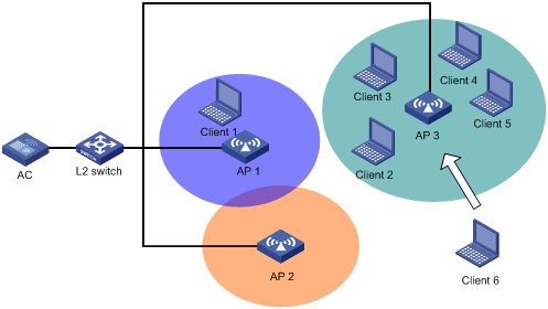
As shown in Figure 4, Client 6 wants to associate with AP 3. AP 3 has reached its maximum load, so it rejects the association request. Then, Client 6 tries to associate with AP 1 or AP 2, but it cannot receive signals from these two APs, so it has to resend an association request to AP 3.
To implement load-balancing, the APs must be managed by the same AC, and the clients can find the APs.
Figure 4 Requirement of WLAN load-balancing implementation
Load-balancing modes
The AC supports two load balancing modes: session mode and traffic mode.
· Session mode load-balancing:
Session-mode load balancing is based on the number of clients associated with the AP/radio.
As shown in Figure 5, Client 1 is associated with AP 1, and Client 2 through Client 6 are associated with AP 2. The AC has session-mode load balancing configured: the maximum number of sessions is 5, and the maximum session gap is 4. Then, Client 7 sends an association request to AP 2. The maximum session threshold and session gap have been reached on AP 2, so AP 2 rejects the request. Finally, Client 7 associates with AP 1.
Figure 5 Network diagram for session-mode load balancing

· Traffic mode load-balancing
Traffic snapshot is considered for traffic mode load balancing.
As shown in Figure 6, Client 1 and Client 2 that run 802.11g are associated with AP 1. The AC has traffic-mode load balancing configured: the maximum traffic threshold is 10%, and the maximum traffic gap is 20%. Then, Client 3 wants to access the WLAN through AP 1. The maximum traffic threshold and traffic gap (between AP 1 and AP 2) have been reached on AP 1, so AP 1 rejects the request. Finally, Client 3 associates with AP 2.
Figure 6 Network diagram for traffic-mode load balancing

Load-balancing methods
The AC supports AP-based load balancing and group-based load balancing.
AP-based load balancing can be implemented either among APs or among the radios of an AP.
¡ AP-based load balancing—APs can carry out either session-mode or traffic-mode load balancing. An AP starts load balancing when the maximum threshold and gap are reached, and it does not accept any association requests unless the load decreases below the maximum threshold or the gap is less than the maximum gap. However, if a client has been denied more than the specified maximum times, the AP considers that the client is unable to associate with any other APs, and it accepts the association request from the client.
¡ Radio-based load balancing—The radios of a balanced AP can carry out either session-mode or traffic-mode load balancing. A radio starts load balancing when the maximum threshold and gap are reached, and it will reject any association requests unless the load decreases below the maximum threshold or the gap is less than the maximum gap. However, if a client has been denied more than the specified maximum times, the AP considers that the client is unable to associate with any other APs, and it accepts the association request from the client.
To balance loads among the radios of different APs, you can add them to the same load balancing group.
The radios in a load balancing group can carry out either session-mode or traffic-mode load balancing. The radios that are not added to any load balancing groups do not carry out load balancing. A radio in a load balancing group starts load balancing when the maximum threshold and gap are reached on it, and it does not accept any association requests unless the load decreases below the maximum threshold or the gap is less than the maximum gap. However, if a client has been denied more than the specified maximum times, the AP considers that the client is unable to associate with any other APs, and it accepts the association request from the client.
Configuring the AC to accept APs with a different software version
An AP is a zero-configuration device. It can automatically discover an AC after it is powered on. To make sure an AP can associate with an AC, their software versions must be consistent by default, which complicates maintenance. This task allows the AC to accept APs with a different software version.
Upgrading APs
An improper AP version can cause network problems when you upgrade versions for a large amount of APs at one time. To avoid the problem, you can upgrade a single AP, a group of APs, and all APs as needed.
You can configure the version upgrade function on the Advanced > AP, AP > AP Group, and AP > AP Setup pages. The configuration priorities on these pages are in ascending order. If this function is not configured on one of the pages, configuration with a lower priority is used. For example, if this function is not configured on the AP > AP Setup page, the AP uses the configuration on the AP > AP Group page. If this function is not configured on the AP > AP Group page either, the AP uses the configuration on the Advanced > AP page.
If the version upgrade function is disabled, the AP and the AC establish a tunnel with each other without checking their versions.
If the version upgrade function is enabled, the AC checks the AP's version before establishing a tunnel. If their versions are different, the AP downloads a new version from the AC and restarts.
|
|
NOTE: If you enable the version upgrade function on the AC after an AC-AP tunnel has been established, restart the AP manually so that the AP can automatically download a new version from the AC. |
Switching to fat AP
You can switch the working mode of an AP between the fit mode and the fat mode.
Wireless location
Support for this feature depends on the device model. For more information, see "About the H3C Access Controllers Web-Based Configuration Guide."
Wireless location is a technology to locate, track and monitor specified devices by using WiFi-based Radio Frequency Identification (RFID) and sensors. With this function enabled, APs send Tag or MU messages to a location server, which performs location calculation and then sends the data to the graphics software. You can get the location information of the assets by maps, forms, or reports. Meanwhile, the graphics software provides the search, alert and query functions to facilitate your operations.
Wireless location can be applied to medical monitoring, asset management, and logistics, helping users effectively manage and monitor assets.
Architecture of the wireless location system
A wireless location system is composed of three parts: devices or sources to be located, location information receivers, and location systems.
· Devices or sources to be located include Tags (small, portable RFIDs, which are usually placed or glued to the assets to be located) of a location server company or Mobile Units (MU), and MUs (wireless terminals or devices running 802.11). The tags and MUs can send wireless messages periodically.
· Location information receivers include 802.11 APs.
· Location systems include the location server, calculation software of a location server company, and different types of graphics software.
Wireless location method
Before locating wireless devices, configure a wireless location method in either of the following methods so that the AP can get an IP address of the location server:
· Dynamic wireless location—The AP gets an IP address of the location server from packets sent from the location server. Only location servers of AeroScout support this method.
· Static wireless location—An IP address of the location server is manually configured on the AC.
Wireless locating process
A wireless location system can locate wireless clients, APs, rogue APs, rogue clients, Tags and other devices supporting WLAN protocols. All wireless devices except Tags will be identified as MUs by the wireless location system.
1. Send Tag and MU messages:
A Tag message is a message sent by an RFID. A Tag message contains the channel number so that an AP can filter Tag messages whose channel numbers are not consistent with the AP's operating channel. To make sure more Tags can be detected by the AP, a Tag sends messages on different channels. A Tag periodically sends messages on one or multiple pre-configured channels, and then periodically sends location messages on channels 1, 6, and 11, in turn.
MU messages are sent by standard wireless devices. An MU message does not contain the channel number, so an AP cannot filter MU messages whose channel numbers are not consistent with the AP's operating channel or illegal packets. The filtering is done by the location server, according to a certain algorithm and certain rules.
2. Collect Tag and MU messages:
The working mode of an AP determines how it collects Tag and MU messages.
¡ When the AP operates in normal mode and is bound to an enabled wireless service, it can locate wireless clients associated or not associated with it or other wireless devices, including Tags. The wireless location system considers wireless clients associated with the AP as wireless clients, and considers wireless clients or other wireless devices not associated with the AP as unknown devices.
¡ When the AP operates in normal mode and is not bound to any wireless services or the wireless service is disabled, it can only locate wireless clients not associated with it or other wireless devices.
¡ When the AP operates in monitor mode or hybrid mode, it can locate wireless clients or other wireless devices that are not associated with it. H3C does not recommend this mode because frequent channel change might affect Tag locating performance.
|
|
NOTE: · For more information about monitor mode and hybrid mode, see "Configuring WLAN security." · An AP operates in normal mode when it functions as a WLAN access point. For more information, see "Configuring access services." |
After the processes, the AP begins to collect Tag and MU messages.
¡ Upon receiving Tag messages (assume that the Tags mode has been configured on the AC, and the location server has notified the AP to report Tag messages), the AP checks the Tag messages, encapsulates those passing the check, and reports them to the location server. The AP encapsulates Tag messages by copying all the information (including the message header and payload) except the multicast address, and adding the BSSID, channel, timestamp, data rate, RSSI, SNR, and radio mode of the radio on which the relevant Tag messages were received.
¡ Upon receiving MU messages (assume that the MUs mode has been configured on the AC, and the location server has notified the AP to report MU messages), the AP checks the messages, encapsulates those that pass the check, and reports the messages to the location server. The AP encapsulates an MU message by copying its source address, Frame Control field, and Sequence Control field, and adding the BSSID, channel, timestamp, data rate, RSSI, SNR, and radio mode of the radio on which the relevant Tag messages were received.
3. Calculate the locations of Tags or MUs:
After receiving Tag and MU messages from APs, the location server uses an algorithm to calculate the locations of the Tag and MU devices according to the RSSI, SNR, radio mode, and data rate carried in the messages, and displays the locations on the imported map. Typically, a location server can calculate the locations if more than 3 APs report Tag or MU messages.
Wireless location protocols
An AP supports the following wireless location protocols:
· AeroScout protocol—A protocol made by AeroScout for communications between location servers and APs. It supports both dynamic and static wireless location methods.
· General wireless location protocol—A protocol made by H3C for communications between location servers and APs. It supports only the static wireless location method.
Wireless location rate limiting
The AeroScout protocol uses the dilution feature to reduce the MU messages when a WLAN is busy. However, when the network is not busy, the dilution feature might cause location failures that result from MU message loss.
To resolve this problem, you can configure wireless location rate limiting to prevent excessive MU messages from affecting the operation of the network and location server.
· AP-based rate limiting—Rate limits the MU messages from all APs.
· Client-based rate limiting—Rate limits the MU messages for each client.
CUPID location
Capturing User Positioning Including Direct path (CUPID) location can precisely locate multiple clients. It is more immune to interferences, multipath effect, deployment density, and environment changes than other location methods.
Wireless sniffer
Support for this feature depends on the device model. For more information, see "About the H3C Access Controllers Web-Based Configuration Guide."
In a wireless network, it is difficult to locate signal interference or packet collision by debugging information or terminal display information of WLAN devices. To facilitate the troubleshooting, configure an AP as a packet sniffer to listen to, capture, and record wireless packets. The sniffed packets are recorded in the .dmp file for troubleshooting.
As shown in Figure 7, enable wireless sniffer on the Capture AP. The Capture AP is able to listen to the wireless packets in the network. Administrators can download the .dmp file to the PC and make further analysis.
The device supports the following wireless sniffer methods:
· Radio-based—If you enable WLAN sniffer on a radio of the AP, the radio can capture control, management, and data packets that it can monitor on its working channel.
· Client-based—You can use this method to capture management, control, and data packets sent or received by specified clients. The packets contain client connection or status update information.

AP provision
AP provision enables you to configure network settings for fit APs on the AC. The AC automatically assigns these settings to the fit APs in run state over tunnel connections. The settings are stored in the proprietary configuration file on each AP and take effect after the AP restarts. This feature avoids configuring network settings for APs one by one from a terminal, reducing the work load in large WLAN networks.
Band navigation
The 2.4 GHz band is often congested. Band navigation enables APs to accept dual-band (2.4 GHz and 5 GHz) clients on their 5 GHz radio, increasing overall network performance.
When band navigation is enabled, the AP directs clients to its 2.4 GHz or 5 GHz radio by following these principles:
· For a 2.4 GHz client, the AP associates with the client after rejecting it several times.
· For a dual-band client, the AP directs the client to its 5 GHz radio.
· For a 5 GHz client, the AP associates with the client on its 5 GHz radio.
The AP verifies the RSSI of a dual-band client before directing the client to the 5 GHz radio. If the RSSI is lower than the specified value, the AP does not direct the client to the 5 GHz band.
If the number of clients on the 5 GHz radio reaches the upper limit, and the gap between the number of clients on the 5 GHz radio and that on the 2.4 GHz radio reaches the upper limit, the AP denies the client's association to the 5 GHz radio and allows new clients to associate with the 2.4 GHz radio. If a client has been denied more than the maximum number of times on the 5 GHz radio, the AP considers that the client is unable to associate with any other APs, and it allows the 5 GHz radio to accept the client.
BAS AC
Support for this feature depends on the device model. For more information, see "About the H3C Access Controllers Web-Based Configuration Guide."
An H3C cannot act as a master AC.
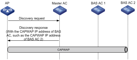
Overview
MAC-BAC provides an AC deployment method to simplify AC management.
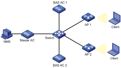
MAC-BAC defines a master AC and multiple BAS ACs. As shown in Figure 8, the master AC manages the BAS ACs, and the BAS ACs provide WLAN access and authentication.
The master AC resides between the BAS ACs and the authentication server. Among the ACs, only the master AC communicates with the authentication server, and the BAS ACs communicate with the master AC to complete authentication. From the authentication server's perspective, there is only one AC on the WLAN.
MAC-BAC operating mechanism
Before a master AC can manage the BAS ACs, it must establish a tunnel with each BAS AC. After the tunnels are established, each BAS AC reports local information to the master AC, including IP address used to establish a tunnel with APs, IP address of the BAS AC, the number of online APs, and IP addresses of clients associated with the APs.
The master AC and BAS ACs exchange information through tunnels.
MAC-BAC operates as follows:
1. The master AC establishes tunnels with BAS ACs.
2. An AP obtains the IP address of the master AC from the Option field in the reply sent by the DHCP server (recommended).
An AP can also obtain an IP address in other ways.
3. The AP unicasts a discovery request to the master AC.
4. The master AC returns a discovery response that contains the CAPWAP IP address of the BAS AC with the lowest workload.
5. The AC establishes a tunnel with the specified BAS AC.
6. The BAS AC reports the AP information to the master AC so that the master AC can manage the BAS ACs.
Figure 9 Network diagram
|
|
NOTE: H3C recommends that you use Option to obtain the IP address of the master AC. |
VLAN pool
A VLAN pool contains a group of VLANs. It can assign VLAN IDs only to wireless clients.
Multicast optimization
Support for this feature depends on the device model. For more information, see "About the H3C Access Controllers Web-Based Configuration Guide."
WLAN selects the lowest transmit rate for multicast packets and provides no multicast retransmission mechanism. Therefore, WLAN cannot meet the requirements of some multicast applications that are not delay-sensitive but are data-integrity sensitive, such as HD VoD. The multicast optimization feature can solve these problems by enabling APs to convert multicast packets to unicast packets, so WLAN can provide retransmission service and higher transmit rates for the converted unicast packets.
Unless otherwise specified, the unicast packets in this chapter refer to the wireless unicast packets that have the priority of video.
Figure 10 Multicast data transmission when multicast optimization is enabled
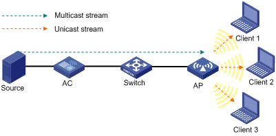
With multicast optimization enabled, the AP listens to the IGMP reports and leave messages sent by clients. When the AP receives an IGMP report, it adds or updates a multicast optimization entry and updates the multicast source addresses allowed by the client (for IGMPv3 and MLDv2 packets). When the AP receives an IGMP leave message or when a multicast optimization entry ages out, the AP removes the entry. When the AP is disconnected from the AC, or when multicast optimization is disabled, all multicast optimization entries are removed.
After creating multicast entries, the AP listens to non-IGMP and non-MLD multicast packets sent from the multicast source to clients, and matches the multicast address of the packets to the multicast optimization entries. If a match is found, the AP converts the multicast packets to unicast packets and sends the unicast packets to all the clients in the multicast entries. If no match is found, the AP directly sends the multicast packets.
To avoid performance degradation, you can configure the maximum number of clients that multicast optimization can support. When the maximum number is reached, the AC takes either of the following actions, depending on which one is configured:
· Halt—A new client can join a multicast group and receive multicast packets, and a multicast optimization entry can be created for the client. However, the multicast optimization function for all clients in the multicast group becomes invalid. When the number of clients drops below the upper limit, the multicast optimization function takes effect again.
· Reject-client—A new client can join a multicast group, but no new multicast optimization entries can be created. If multicast optimization entries have been created for other clients in the multicast group, the client cannot receive multicast packets. Otherwise, the client can receive multicast packets.
|
|
NOTE: If you configure Halt first, and then configure Reject-client, the existing multicast optimization entries still take effect. |
Guest access tunnel
Support for this feature depends on the device model. For more information, see "About the H3C Access Controllers Web-Based Configuration Guide."
A guest access tunnel redirects guest traffic to the external network of a company, providing WLAN access for guests and ensuring data security in the external network at the same time.
The guest access tunnel function is realized through an aggregation AC and an edge AC. The edge AC is deployed in the internal network to provide access and authentication services to internal users. The aggregation AC is deployed in the external network to process guest traffic. After a guest access tunnel is established between the edge AC and aggregation AC, guests get online through the specified guest VLAN, and guest traffic is forwarded to the aggregation AC.
Guest access tunnels support NAT traversal. If a NAT device is deployed between the edge AC and the aggregation AC, a guest access tunnel can still be established.
Figure 11 Network diagram

Bonjour gateway
Support for this feature depends on the device model. For more information, see "About the H3C Access Controllers Web-Based Configuration Guide."
Bonjour is a set of zero configuration network protocols developed by Apple Inc based on Multicast DNS (mDNS) services. Bonjour is designed to make network configuration easier for users. It enables Apple devices to automatically advertise service information and enables clients to automatically discover Apple devices without obtaining information about the devices.
However, Bonjour supports only link-local multicast addresses. To address this issue, the AC can act as a Bonjour gateway to manage clients and devices providing services and forward mDNS packets across VLANs, enabling Bonjour to be applied in large scale networks.
Benefits
Bonjour gateway provides the following benefits:
· mDNS traffic control.
· User-defined Bonjour policies to restrict services that can be used by clients.
· Inter-VLAN forwarding of mDNS packets, enhancing network availability.
· Bonjour policy application in views of multiple levels.
Working mechanism
|
|
IMPORTANT: · The Bonjour gateway discards queries received from the wired network. · The Bonjour gateway filters queries and responses according to user-defined Bonjour policies. This section focuses on only the Bonjour gateway working mechanism. For more information about Bonjour policies, see "Configuring a Bonjour policy." |
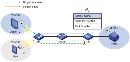
· Bonjour service advertisement snooping
The service devices send Bonjour responses to advertise their supporting services. Upon receiving the Bonjour responses, the AC creates a service-device mapping table to store service information about the service devices. When a client queries for a service, the Bonjour gateway searches the service-device mapping table and sends a response to the client.
As shown in Figure 12, Bonjour service advertisement snooping operates as follows:
a. Apple TV and Print send Bonjour responses to advertise their supporting services.
b. Upon receiving the Bonjour responses, the AC creates a service-device mapping table to store service information about Apple TV and Print.
c. iPad queries for the service of Apple TV or Print and the AC sends a response to iPad.
Figure 12 Bonjour service advertisement snooping
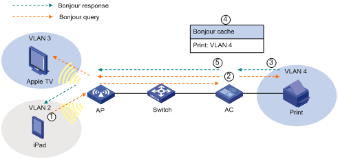
· Bonjour query snooping and response
When a client queries for a service that is not in the service-device mapping table, the Bonjour gateway forwards the query. After receiving a response, the Bonjour gateway adds the service information to the service-device mapping table and forwards the response to the client.
As shown in Figure 13, Bonjour query snooping and response operates as follows:
a. iPad queries for the printing service, and the AP sends the query to the AC through the CAPWAP tunnel.
b. The AC forwards the query to the configured VLANs because it does not find any printing service entries in the service-device mapping table.
c. Upon receiving the query, the print service sends a response to the AC.
d. The AC adds the service information to the service-device mapping table and forwards the response to iPad.
The AC can respond by searching the service-device mapping table next time when a client queries the printing service.
Figure 13 Bonjour query snooping and response
Hotspot 2.0
Support for this feature depends on the device model. For more information, see "About the H3C Access Controllers Web-Based Configuration Guide."
Hotspot 2.0, developed based on 802.11u, implements automatic network discovery, automatic authentication, and seamless roaming for wireless clients.
The AC supports the following functions in Hotspot 2.0:
· Automatic network discovery—The AC and clients exchange Hotspot 2.0 capabilities by using active or passive scanning. If both of them support Hotspot 2.0, the clients can get external network information by exchanging Generic Advertisement Service (GAS) frames with the AC before being associated with an AP.
· Security—When the Downstream Group-Addressed Forwarding (DGAF) function is enabled for an AP, the AP forwards all downstream wireless broadcast ARP packets and wireless multicast packets. To prevent spoofing attacks by using downstream multicasts, you can disable the DGAF function for the AP.
· Network management—Controls frame transmission between clients and the AC.
Configuring WLAN advanced settings
Setting a country/region code
1. Select Advanced > Country/Region Code from the navigation tree.
Figure 14 Setting a country/region code
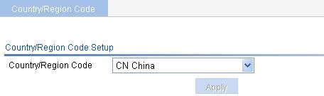
2. Configure a country/region code as described in Table 1.
3. Click Apply.
|
Item |
Description |
|
Country/Region Code |
Select a country/region code. Configure the valid country/region code for a WLAN device to meet the country regulations. If the list is grayed out, the setting is preconfigured to meet the requirements of the target market and is locked. It cannot be changed. |
If you do not specify a country/region code for an AP, the AP uses the global country/region code configured on this page. If an AP is configured with a country/region code, the AP uses its own country code. For information about how to specify the country/region code for an AP, see "Configuring APs."
Some ACs and APs have fixed country/region codes. The codes to be used are determined as follows:
· An AC's fixed country/region code cannot be changed, and all managed fit APs whose country/region codes are not fixed must use the AC's fixed country/region code.
· A fit AP's fixed country/region code cannot be changed, and the fit AP can only use the country/region code.
· If an AC and a managed fit AP use different fixed country/region codes, the fit AP uses its own fixed country/region code.
Configuring 1+1 AC backup
Configuring an AP connection priority
1. Select AP > AP Setup from the navigation tree.
2. Click the icon ![]() for the target AP.
for the target AP.
3. Expand the Advanced Setup area.
Figure 15 Configuring an AP connection priority
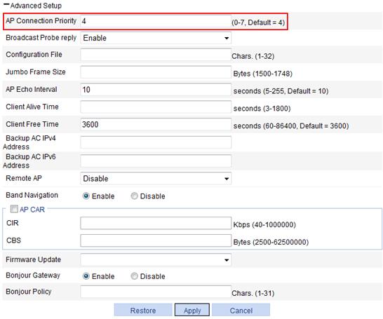
4. Configure an AP connection priority as described in Table 2.
5. Click Apply.
|
Item |
Description |
|
AP Connection Priority |
Set the priority for the AP connection to the AC. |
Configuring 1+1 AC backup
1. Select Advanced > AC Backup from the navigation tree.
Figure 16 Configuring AC backup
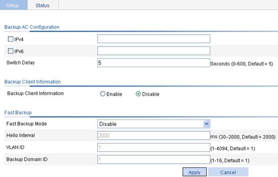
2. Configure an IP address for the backup AC as described in Table 3.
3. Click Apply.
|
Item |
Description |
|
|
IPv4 |
Enter the IPv4 address of the backup AC. |
If the backup AC is configured on the page you enter by selecting AP > AP Setup, the configuration on this page is used first. For more information, see "Configuring APs." The access mode configuration on the two ACs must be the same. Specify the IP address of one AC on the other AC in an AC backup. Support for AC backup varies with the device model. For more information, see "About the H3C Access Controllers Web Configuration Guide." |
|
IPv6 |
Enter the IPv6 address of the backup AC. |
|
|
Switch Delay |
Delay time for the AP to switch from the backup AC to the primary AC. |
|
Configuring 1+1 fast backup
1. Select Advanced > AC Backup from the navigation tree to enter the page shown in Figure 16.
2. Configure fast backup as described in Table 4.
3. Click Apply.
|
Item |
Description |
|
Fast Backup Mode |
· disable—Disable fast backup. · enable—Enable fast backup. By default, fast backup is disabled. |
|
Hello Interval |
Heartbeat interval for an AC connection. If no heartbeat is received during the continuous three intervals, the device considers the peer down. The value range varies with devices. For more information, see "About the H3C Access Controllers Web-Based Configuration Guide." |
|
VLAN ID |
ID of the VLAN to which the port where the backup is performed belongs. |
|
Backup Domain ID |
ID of the domain to which the AC belongs. |
|
|
NOTE: · Support for 1+1 fast backup varies with the device model. For more information, see "About the H3C Access Controllers Web-Based Configuration Guide." · For EWPX2WCMD0, LSRM1WCM3A1, and LSQM1WCMD0, make sure interface Ten-GigabitEthernet 1/0/1 is in up state, and is assigned to the configured VLAN in Figure 16. · For WX5004, WX5002V2, WX3510E, and WX3540E devices, H3C recommends that you set the heartbeat interval to be greater than 1.2 seconds. · For EWPX1WCMD0, LSQM1WCMD0, LSRM1WCM3A1, and LSUM3WCMD0, if the heartbeat interval is less than 1000 milliseconds and the two Ten-GigabitEthernet interfaces are aggregate interfaces, do not shutdown any one of the two interfaces. · For EWPXM1WCME0 and LSUM1WCME0, if the heartbeat interval is less than 1000 milliseconds and the four Ten-GigabitEthernet interfaces are aggregate interfaces, do not shutdown any one of the four interfaces. |
Displaying status information for 1+1 fast backup
1. Select Advanced > AC Backup from the navigation tree.
2. Click the Status tab.
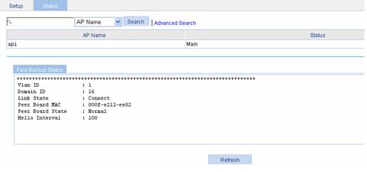
Table 5 Field description
|
Field |
Description |
|
AP Name |
Display the AP connecting to the AC. |
|
Status |
Current status of the AC. |
|
Vlan ID |
ID of the VLAN to which the port belongs. |
|
Domain ID |
Domain to which the AC belongs. |
|
Link State |
Link status of the AC connection: · Close—No connection is established. · Init—The connection is being set up. · Connect—The connection has been established. |
|
Peer Board MAC |
MAC address of the peer AC. |
|
Peer Board State |
Status of the peer AC. · Normal—The peer AC is normal. · Abnormal—The peer AC is malfunctioning. · Unknown—No connection is present. |
|
Hello Interval |
Heartbeat interval for an AC connection. |
Configuring 1+N AC backup
Configuring an AP connection priority
1. Select AP > AP Setup from the navigation tree.
2. Click the icon ![]() for the target AP.
for the target AP.
3. Expand Advanced Setup to enter the page as shown in Figure 15.
4. Configure a connection priority as described in Table 2.
5. Click Apply.
Configuring 1+N AC backup
1. Select AP > AP Setup from the navigation tree.
2. Click the ![]() icon for the target
AP.
icon for the target
AP.
3. Expand Advanced Setup.
Figure 18 Configuring 1+N AC backup
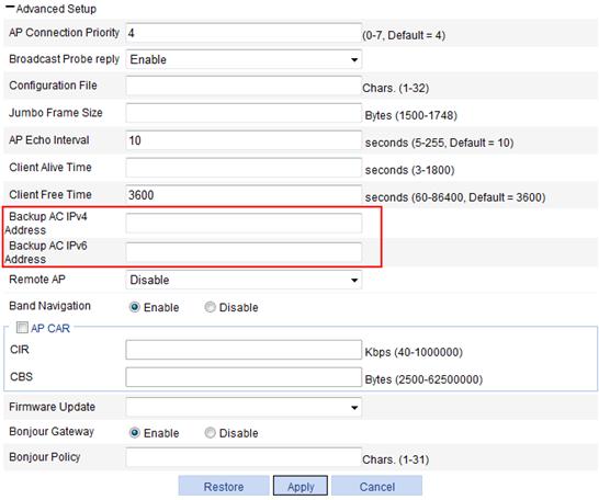
4. Configure 1+N backup as described in Table 6.
5. Click Apply.
|
Item |
Description |
|
|
Backup AC IPv4 Address |
Set the IPv4 address of the backup AC. |
If the global backup AC is also configured on the page you enter by selecting Advanced > AC Backup, the configuration on this page is used first. |
|
Backup AC IPv6 Address |
Set the IPv6 address of the backup AC. |
|
Configuring client information backup
Before performing this task, establish an IACTP tunnel (see "Configuring WLAN roaming") and configure AC backup (see Configuring 1+1 AC backup) on the two ACs.
By default, client information backup is disabled. H3C recommends that you enable client information backup after the configuration of 1+1 AC backup and IACTP tunnel. 1+1 AC backup takes effect only if client information backup is enabled on both ACs.
To configure client information backup:
1. Select Advanced > AC Backup from the navigation tree.
You are placed on the Setup tab. See Figure 16.
2. Select Enable to the right of Backup Client Information.
3. Click Apply.
Configuring continuous transmitting mode
1. Select Advanced > Continuous Transmit from the navigation tree.
Figure 19 Configuring continuous transmitting mode
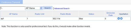
2. Click the ![]() icon for the
target radio. The transmission rate varies with radio
mode.
icon for the
target radio. The transmission rate varies with radio
mode.
¡ When the radio mode is 802.11a/b/g, the page shown in Figure 20 appears. Select a transmission rate from the list.
Figure 20 Selecting a transmission rate (802.11a/b/g)

¡ When the radio mode is 802.11n, the page shown in Figure 21 appears. Select an MCS index value to specify the 802.11n transmission rate. For more information about MCS, see "Configuring radios."
Figure 21 Selecting an MCS index (802.11n)

¡ When the radio mode is 802.11ac, the page shown in Figure 22 appears. Select a VHT MCS index value and a VHT NSS index value to specify the 802.11ac transmission rate. For more information about VHT MCS and VHT NSS, see "Configuring radios."
Figure 22 Transmission rate (802.11ac)
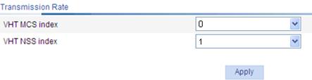
3. Click Apply.
4. To stop the continuous transmitting mode:
¡ Click the ![]() icon for the target
radio.
icon for the target
radio.
¡ Or, select the target radio and click Stop.
After the continuous transmit is stopped, the transmission rate value on the page shown in Figure 20 is displayed as 0.
|
|
NOTE: When continuous transmit is enabled, do not perform any operations other than transmission rate configuration. |
Configuring a channel busy test
1. Select Advanced > Channel Busy Test from the navigation tree.
Figure 23 Configuring a channel busy test

2. Click the ![]() icon for the target AP.
icon for the target AP.
Figure 24 Testing busy rate of channels
3. Configure channel busy test as described in Table 7.
4. Click Start to start the testing.
|
Item |
Description |
|
AP Name |
Display the AP name. |
|
Radio Unit |
Display the radio unit of the AP. |
|
Radio Mode |
Display the radio mode of the AP. |
|
Test Time Per Channel |
Set a time period in seconds within which a channel is tested. |
|
|
NOTE: · During a channel busy test, the AP does not provide any WLAN services. All the connected clients are disconnected. · Before the channel busy test completes, do not start another test for the same channel. |
Configuring load balancing
Band navigation and load balancing can be used simultaneously.
Configuration prerequisites
Before you configure load balancing, verify that:
· The target APs are associated with the same AC.
· The clients can find the APs.
· The fast association function is disabled. By default, the fast association function is disabled. For more information about fast association, see "Configuring access services."
Recommended configuration procedure
|
Task |
Remarks |
|
Required. |
|
|
Required. H3C recommends that you complete Configuring a load balancing mode first. A load balancing group takes effect only when a load balancing mode is configured. |
|
|
Optional. This configuration takes effect for both AP-based load balancing and radio group-based load balancing. |
Configuring a load balancing mode
If the AC has a load balancing mode configured but does not have any load balancing groups created, it uses AP-based load balancing by default.
1. Configure session-mode load balancing:
a. Select Advanced > Load Balance from the navigation tree.
b. Select Session from the Load Balance Mode list.
c. Click Apply.
Figure 25 Setting session-mode load balancing

|
Item |
Description |
|
Load Balance Mode |
Select Session. The function is disabled by default. |
|
Threshold |
Load balancing is carried out for a radio when the session threshold and session gap threshold are reached. |
|
Gap |
Load balancing is carried out for a radio when the session threshold and session gap threshold are reached. |
2. Configure traffic-mode load balancing:
a. Select Advanced > Load Balance from the navigation tree.
b. Select Traffic from the Load Balance Mode list.
c. Click Apply.
Figure 26 Setting traffic-mode load balancing

|
Item |
Description |
|
Load Balance Mode |
Select Traffic. The function is disabled by default. |
|
Traffic |
Load balancing is carried out for a radio when the traffic threshold and traffic gap threshold are reached. |
|
Gap |
Load balancing is carried out for a radio when the traffic threshold and traffic gap threshold (the traffic gap between the two APs) are reached. |
|
|
NOTE: The maximum throughput for 802.11g/802.11a, 802.11b, and 802.11n are 30 Mbps, 7 Mbps, and 250 Mbps, respectively. |
Configuring group-based load balancing
H3C recommends that you complete Configuring a load balancing mode on the Load Balance tab. A load balancing group takes effect only when a load balancing mode is configured.
To configure group-based load balancing:
1. Select Advanced > Load Balance from the navigation tree.
2. Click the Load Balance Group tab.
3. Click Add.
Figure 27 Configuring a load balancing group

4. Configure a load balancing group as described in Table 10.
5. Click Apply.
|
Item |
Remarks |
|
Group ID |
Display the ID of the load balancing group. |
|
Description |
Configure a description for the load balancing group. By default, the load balancing group has no description. |
|
Radio List |
· In the Radios Available area, select the target radios, and then click << to add them to the Radios Selected area. · In the Radios Selected area, select the radios to be removed, and then click >> to remove them from the load balancing group. |
Configuring parameters that affect load balancing
1. Select Advanced > Load Balance from the navigation tree. See Figure 25.
2. Configure parameters that affect load balancing as described in Table 11.
3. Click Apply.
|
Item |
Remarks |
|
Max Denial Count |
Maximum denial count of client association requests. If a client has been denied more than the specified maximum times, the AP considers that the client is unable to associate with any other APs and accepts the association request from the client. |
|
RSSI Threshold |
Load balancing RSSI threshold. A client may be detected by multiple APs. An AP considers a client whose RSSI is lower than the load balancing RSSI threshold to be not detected. If only one AP can detect the client, the AP increases the access probability for the client even if it is overloaded. |
Configuring AP
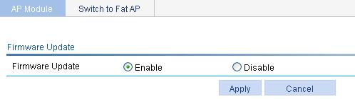
Upgrading AP version
1. Select Advanced > AP from the navigation tree.
2. On the AP Module tab, select Enable.
3. Click Apply.
|
|
NOTE: You can configure the version upgrade function on the Advanced > AP Setting, AP > AP Group, and AP > AP Setting pages to upgrade a single AP, a group of APs, and all APs as needed. See Upgrading APs. |
Figure 28 Upgrading AP version
Configuring the AC to accept APs with a different software version
1. Select Advanced > AP from the navigation tree.
2. On the AP Module tab, select the desired AP.
3. Click Version Set.
4. Configure AP settings as described in Table 12.
5. Click Apply.
|
Item |
Description |
|
AP Model |
Display the selected AP model. |
|
Software Version |
Enter the software version of the AC in the correct format. |
Switching to fat AP
1. Select Advanced > AP Setup from the navigation tree.
2. Click the Switch to Fat AP tab.
3. Select the desired AP.
4. Click Switch to Fat AP to perform AP working mode switchover.
|
|
NOTE: Before you switch the work mode, you must download the fat AP software to the AP. |
Configuring wireless location
1. Select Advanced > Wireless Location from the navigation tree.
Figure 29 Configuring wireless location

2. Configure wireless location as described in Table 13.
3. Click Apply.
|
Item |
Description |
|
Location Function |
· Enable—Enable the wireless location function. The device begins to listen to packets when wireless location is enabled. · Disable—Disable wireless location. To ensure the location function, complete the configuration on the location server and AC: · On the location server—Configure whether to locate Tags or MUs, Tag message multicast address, and dilution factor on the location server. These settings will be notified to the APs through the configuration message. For more information about location server and configuration parameters, see the location server manuals. · On the AC—Configure the AP mode settings, and enable the wireless location function. When configurations are made correctly, APs wait for the configuration message sent by the location server. After receiving that message, the APs start to receive and report Tag and MU messages. |
|
Protocol Type |
Specify a wireless location protocol. · Aero Scout—Use the AeroScout protocol. · General—Use the general location protocol. |
|
General Mode |
Specify a wireless location general mode: Fingerprint or CUPID. |
|
Address Acquisition Method |
Specify a wireless location method. · Static—Apply the static location mode. · Dynamic—Apply the dynamic location mode. |
|
Vendor Port |
Set the vendor port number in the XML file on the AeroScout location server, in the range of 0 to 65535. By default, the port number is 1144. |
|
Ignored Frame Type |
Ignore beacon frames. |
|
RSSI Threshold |
Specify the RSSI threshold for the location packets, in the range of 5 to 100. |
|
AP Rate Limit |
Configure the following rates for the AP: · CIR—Specify the CIR for the location packets from the AP, in the range of 8 to 1300000 Kbps. · CBS—Specify the CBS for the location packets from the AP, in the range of 500 to 130000000 bytes. |
|
Client Rate Limit |
Configure the following rates for the clients: · CIR—Specify the CIR for the location packets from the clients, in the range of 1 to 1300000 Kbps. · CBS—Specify the CBS for the location packets from the clients, in the range of 80 to 130000000 bytes. |
|
AP Report |
AP reporting status: Enable or Disable. |
|
AP Report Interval |
Set the AP reporting interval in the range of 1 to 10 seconds. |
|
Address Configuration |
Specify the view in which the IP address of the location server is configured. · AP Group Table—Configure the IP address of the location server in AP group view. · AP Table—Configure the IP address of the location server in AP template view. |
|
Dilution Factor |
Specify the dilution factor for the location packets, in the range of 1 to 10000. |
|
Dilution Timeout |
Specify the dilution timeout for the location packets, in the range of 1 to 60 seconds. |
|
Engine Address |
Specify the IP address of the location server. |
An AP reports IP address change and device reboot events to the location server so that the location server is able to respond in time. The AP reports a reboot message according to the IP address and port information of the location server recorded in its flash.
· The AP updates the data in the flash after receiving a configuration message. To protect the flash, the AP does not update the flash immediately after receiving a configuration message, but waits for 10 minutes. If the AP receives another configuration message within 10 minutes, it only updates the configuration information in the cache, and when the 10-minute timer is reached, it saves the cache information in the flash.
· If the AP reboots within 10 minutes after receiving the first configuration message, and no configuration is saved in the flash, it does not send a reboot message to the location server.
Configuring wireless sniffer
Configuring radio-based wireless sniffer
When configuring radio-based wireless sniffer, follow these guidelines:
· Auto APs do not support wireless sniffer.
· Before you enable wireless sniffer, make sure the AP operates in run state (select Summary > AP to verify the state of the AP). Wireless sniffer can be enabled for only one radio configured with a fixed channel.
· Wireless sniffer can be enabled only on one radio at one time.
· The working mode of an AP cannot be changed when it is capturing packets.
· Do not enable or run wireless services for the radio with wireless sniffer enabled. Disable all wireless services before enabling wireless sniffer.
· When the Capture AP is capturing packets, if the radio for which the wireless sniffer is disabled, it automatically stops the sniffer operation, and the packets are saved to the file with the specified name in the default storage medium. The default storage medium varies with device models.
To configure radio-based wireless sniffer:
1. Select Advanced > Wireless Sniffer from the navigation tree.
Figure 30 Configuring radio-based wireless sniffer

2. Configure wireless sniffer as described in Table 14.
3. Select Capture Based On Radio.
4. Click Apply.
5. Click the ![]() icon for the target radio.
icon for the target radio.
|
Item |
Description |
|
Capture Limit |
The maximum number of packets that can be captured. If you set a new value for this option, the packets that have been captured are cleared.
· You cannot change the value when the device is capturing packets. · Once the limit is exceeded, the device stops capturing packets. |
|
Filename |
Name of the file to which the packets are saved. By default, the name is CaptureRecord.
You cannot change the file name when the device is capturing packets. |
Configuring client-based wireless sniffer
When configuring client-based wireless sniffer, follow these guidelines:
· Create an Ethernet frame header ACL and configure ACL rules to match the MAC address of clients whose packets you need to capture. The match action should be permit.
· ACL rules only support source MAC address.
· For more information about ACL, see "Configuring ACL and QoS."
To configure client-based wireless sniffer:
1. Select Advanced > Wireless Sniffer from the navigation tree.
Figure 31 Configuring client-based wireless sniffer

2. Configure client-based wireless sniffer as described in Table 14.
3. Select Capture Based On ACL.
4. Click Apply.
5. Enter Ethernet frame ACL ID in the Capture ACL field.
6. Click Start.
Configuring AP provision
If you change the provision settings for an associated AP, save the settings to the proprietary configuration file of the AP, and restart the AP to validate the new settings.
Configuring global provision information
1. Select Advanced > AP Provision from the navigation tree.
2. Click the Global Provision tab.
Figure 32 Configuring global provision information
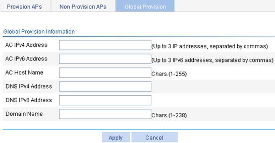
3. Configure global provision as described in Table 15.
4. Click Apply.
|
Item |
Description |
|
|
AC IPv4 Address |
Global IPv4 address of the AC so that all APs can discover the AC. |
· If an item is configured on both the global provision information page and the AP provision information page, the setting on the AP provision information page applies. · The global IPv6 address of an AC cannot be the link local address. |
|
AC IPv6 Address |
Global IPv6 address of the AC so that all APs can discover the AC. |
|
|
AC Host Name |
Global host name of the AC. |
|
|
DNS IPv4 Address |
Global IPv4 address of the DNS server. |
|
|
DNS IPv6 Address |
Global IPv6 address of the DNS server. |
|
|
Domain Name |
Global AP domain name. |
|
Configuring non provision APs
1. Select Advanced > AP Provision from the navigation tree.
2. Click the Non Provision APs tab.
Figure 33 Configuring non provision APs

3. Select the box for the target AP.
4. Configure the AP as described in Table 16.
|
Item |
Description |
|
Change to Provision AP |
Select an AP and click this button to change the selected AP to a provision AP. |
|
Delete Provision |
Select an AP and click this button to delete the proprietary configuration file of the selected AP.
· The Delete Provision operation applies to only running APs. · The Delete Provision operation takes effect only when you manually reboot the APs. |
Configuring provision Aps
|
|
CAUTION: After you click Apply Provision on the AC, the configuration is saved to the wlan_ap_cfg.wcfg file of the specified AP. When the wlan_ap_cfg.wcfg file takes effect, the AP can only be managed by the AC specified on the Global Provision tab or Provision APs tab. Make sure the correct AC is specified. Otherwise, the AP cannot be managed by the specified AC, and you have to log in to the AP to modify its configuration. |
Provision AP settings are not configurable for automatically associated APs (auto APs).
To configure provision APs:
1. Select Advanced > AP Provision from the navigation tree.
2. Click the Provision APs tab.
Figure 34 Configuring provision APs
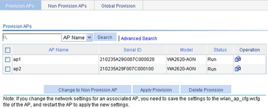
3. Select the box for the target AP.
4. Configure the AP as described in Table 17.
|
Item |
Description |
|
|
Change to Non Provision AP |
Select an AP and click this button to change the selected AP to a non-provision AP. |
|
|
Apply Provision |
Select an AP and click this button to save the provision settings to the proprietary configuration file of the selected AP. |
· The Apply Provision/Delete Provision operation applies to only running APs. · The Apply Provision/Delete Provision operation takes effect only when you manually reboot the APs. · After restart, the AP executes the configuration file, the wlan_ap_cfg.wcfg file, and the configuration file specified on the page you enter by selecting AP > AP Setup in turn. Make sure these three types of files are correct because wrong configurations may make them overwrite or conflict with one another. |
|
Delete Provision |
Select an AP and click this button to clear the proprietary configuration file of the selected AP. |
|
5. To configure AP provision settings:
a. Select Advanced > AP Provision from the navigation tree.
b. Click the Provision APs tab.
c. Click the ![]() icon for the target AP.
icon for the target AP.
Figure 35 Configuring AP provision settings

6. Configure AP provision settings as described in Table 18.
7. Click Apply.
|
Item |
Description |
|
|
IPv4 Address |
IPv4 address of the management VLAN interface of the AP. |
|
|
IPv4 Mask |
IPv4 address mask. |
|
|
IPv6 Address |
IPv6 address of the management VLAN interface of the AP. |
|
|
IPv6 Prefix Length |
Length of IPv6 address prefix. |
|
|
Gateway IPv4 Address |
IPv4 address of the gateway. |
|
|
Gateway IPv6 Address |
IPv6 address of the gateway. |
|
|
DNS IPv4 Address |
IPv4 address of the DNS server. |
|
|
DNS IPv6 Address |
IPv6 address of the DNS server. |
|
|
Domain Name |
Domain name of the AP. |
|
|
Encrypted Type |
· IPsec—The AP encrypts the control tunnel by using IPsec. · No Encryption—The AP does not encrypt the control and data tunnels. By default, the AP does not encrypt control and data tunnels. |
|
|
Data Tunnel Encryption |
Enable the AP to encrypt the data tunnel by using IPsec. By default, the AP does not encrypt the data tunnel. |
|
|
IPsec Key |
Select this option to configure the IPsec key used by the AP. |
|
|
Initial Country Code |
Initial country code used by the AP. |
|
|
802.1X Client Function |
· Disable. · Enable. By default, the 802.1X client function is disabled. |
|
|
802.1X Client Username |
Configure the username for the AP when it operates as an 802.1X client. |
|
|
802.1X Client Password |
Configure the password for the AP when it operates as an 802.1X client. |
|
|
802.1X Client EAPMethod |
Select the authentication method for the AP when it operates as an 802.1X client. |
|
|
AC IPv4 Address |
IPv4 address of the AC so that the AP can discover the AC. |
|
|
AC IPv6 Address |
IPv6 address of the AC so that the AP can discover the AC. |
|
|
AC Host Name |
Host name of the AC. |
|
|
Default VLAN ID |
Default VLAN ID of the Layer 2 Ethernet interface of the AP. |
|
|
Tagged VLAN |
Tagged VLAN IDs on the Layer 2 Ethernet interface of the AP. |
The total number of tagged and untagged VLANs cannot exceed 256. If a VLAN is specified as a tagged VLAN and an untagged VLAN at the same time, the untagged VLAN setting overwrites the tagged VLAN setting. |
|
Untagged VLAN |
Untagged VLAN IDs on the Layer 2 Ethernet interface of the AP. |
|
Configuring band navigation
When band navigation is enabled, client association efficiency is reduced, so this feature is not recommended in a scenario where most clients use 2.4 GHz.
Band navigation is not recommended in a delay-sensitive network.
Band navigation and load balancing can be used simultaneously.
Configuration prerequisites
To enable band navigation to operate correctly, make sure of the following:
· The fast association function is disabled. By default, the fast association function is disabled. For more information about fast association, see "Configuring access services."
· Band navigation is enabled for the AP. By default, band navigation is enabled for the AP.
· The SSID is bound to the 2.4 GHz and 5 GHz radios of the AP.
Configuring band navigation
1. Select Advance > Band Navigation from the navigation tree.
Figure 36 Configuring band navigation

2. Configure band navigation as described in Table 19.
3. Click Apply.
|
Item |
Description |
|
Band Navigation |
· Enable—Enable band navigation. · Disable—Disable band navigation. By default, band navigation is disabled globally. |
|
Session Threshold |
· Session Threshold—Session threshold for clients on the 5 GHz band. · Gap—Session gap, which is the number of clients on the 5 GHz band minus the number of clients on the 2.4 GHz band. If the number of clients on the 5 GHz radio has reached the upper limit, and the gap between the number of clients on the 5 GHz radio and that on the 2.4 GHz radio has reached the upper limit, the AP denies the client’s association to the 5 GHz radio, and allows new clients to associate with the 2.4 GHz radio. |
|
Gap |
|
|
Max Denial Count |
Maximum denial count of client association requests. If a client has been denied more than the maximum times on the 5 GHz radio, the AP considers that the client is unable to associate with any other APs, and allows the 5 GHz radio to accept the client. |
|
RSSI Threshold |
Band navigation RSSI threshold. The AP checks the RSSI of a dual-band client before directing the client to the 5 GHz radio. If the RSSI is lower than the value, the AP does not direct the client to the 5 GHz band. |
|
Aging Time |
Client information aging time. The AP records the client information when a client tries to associate with it. If the AP receives the probe request or association request sent by the client before the aging time expires, the AP refreshes the client information and restarts the aging timer. If not, the AP removes the client information, and does not count the client during band navigation. |
Configuring a BAS AC
If the BAS AC function is disabled, a BAS AC is an ordinary AC.
To configure BAS AC:
1. Select Advanced > BAS AC from the navigation tree.
Figure 37 Configuring BAS AC
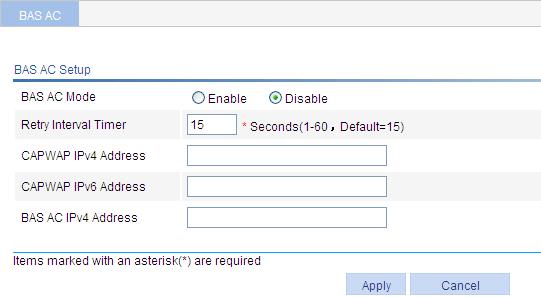
2. Configure BAS AC as described in Table 20.
3. Click Apply.
|
Item |
Description |
|
BAS AC Mode |
· Enable—Enable BAS AC. · Disable—Disable BAS AC. By default, BAS AC is disabled. |
|
Retry Interval Timer |
Specify the interval at which the BAS AC sends connection requests to the master AC. By default, the retry interval is 15 seconds. |
|
CAPWAP IPv4 Address |
The CAPWAP IPv4 or IPv6 address configured on the BAS AC. When you configure the CAPWAP IP address for a BAS AC, make sure the CAPWAP IP address and the IP address of the AP are reachable at Layer 3. You can configure a CAPWAP IPv4 address and a CAPWAP IPv6 address. The two addresses can exist at the same time. |
|
CAPWAP IPv6 Address |
|
|
BAS AC IPv4 address |
The IP address reported to the master AC by the BAS AC. Only an IPv4 address is supported. |
|
|
NOTE: The IP address for the BAS AC to connect to the master AC and the CAPWAP IP address can be the same. |
Configuring a VLAN pool
Creating a VLAN pool
1. Select Advanced > VLAN Pool from the navigation tree.
2. Click Add.
Figure 38 Creating a VLAN pool

3. Configure VLAN pool as described in Table 21.
4. Click Apply.
|
Item |
Description |
|
VLAN Pool |
Specify the name for a VLAN pool. By default, no VLAN pool exists. You can create up to 32 VLAN pools. |
|
VLAN List |
Configure the VLAN list in a VLAN pool. By default, no VLAN list exists in a VLAN pool. Deleting a VLAN in the VLAN list does not affect clients getting online through the VLAN. |
After a VLAN pool assigns a VLAN ID to a client, if the client goes offline and goes online by using the same SSID within a certain time, the VLAN pool assigns the previous VLAN ID rather than a new VLAN ID to the client. In addition, this client is not counted in the number of clients in each VLAN on the VLAN Info tab.
The AP selects a VLAN ID for a client in the following order:
1. VLAN ID assigned by the authentication server.
2. These two kinds of VLAN ID enjoy the same priority:
¡ VLAN ID in the VLAN pool.
¡ VLAN ID specified in the bound service template.
3. VLAN ID bound on the Wireless Service > Access Service page.
Configurations with a higher priority will overwrite the one with lower priority.
Binding a VLAN pool to a specific wireless service
Enable MAC VLAN for the wireless service to be bound to the VLAN pool. Configure the MAC VLAN function on the Wireless Service > Access Service page.
To bind a VLAN pool to a service template:
1. Select Wireless Service > Access Service from the navigation tree.
2. Click the ![]() icon for the target wireless service.
icon for the target wireless service.
Figure 39 Binding a VLAN pool to a wireless service
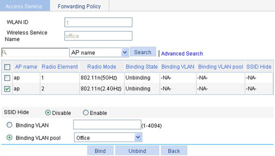
3. Select the AP radio mode to be bound.
4. Select the Binding VLAN pool option and select the target VLAN pool from the Binding VLAN pool list.
5. Click Bind.
Displaying VLAN pool information
1. Select Advanced > VLAN Pool from the navigation tree.
2. Click the VLAN Info tab, and click the target VLAN pool name. You can see the number of online clients for each VLAN.
Figure 40 Displaying number of clients for each VLAN ID

This page displays the number of clients that obtain VLAN IDs through the VLAN pool, but not the clients that obtain VLAN IDs through other methods such as a server-assigned VLAN.
3. Click the VLAN Pool Bound Info tab and click the target VLAN pool name. You can display the VLAN pool binding information.
Figure 41 Displaying VLAN pool binding information

Configuring multicast optimization
In centralized forwarding mode, enable IGMP/MLD snooping on the AC before enabling multicast optimization and configure the aging time of multicast optimization entries to be greater than the aging time of IGMP/MLD snooping dynamic member ports. Whether IGMP/MLD snooping is enabled does not affect the multicast optimization function in local forwarding mode.
To enable multicast optimization to operate correctly in a WLAN roam environment with AC backup, make sure the multicast optimization function is enabled on all ACs on IACTP tunnels. After the primary AC fails, a large number of APs upload multicast optimization entries to the new primary AC. To avoid congestion, the multicast optimization entries will be synchronized to the new primary AC in two minutes.
Enabling multicast optimization
1. Select Advanced > Multicast Optimization from the navigation tree.
Figure 42 Configuring multicast optimization
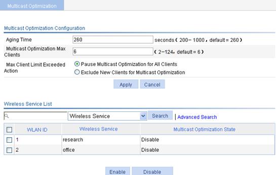
2. Configure multicast optimization as described in Table 22.
3. Click Apply.
|
Item |
Description |
|
Aging Time |
Specify the aging time for multicast optimization entries. If the AP does not receive an IGMP report from a client within the aging time, the AP removes the client from the multicast optimization entry. If you enable IGMP snooping, configure the aging time of multicast optimization entries to be greater than the aging time of IGMP snooping dynamic member ports. |
|
Multicast Optimization Max Clients |
Specify the maximum number of clients supported by multicast optimization. A client can join up to eight multicast groups. If a client joins multiple multicast groups, the client is counted as multiple clients in multicast optimization statistics. For example, if a client has joined two multicast groups, the client is counted as two clients in the multicast optimization statistics. |
|
Max Client Limit Exceeded Action |
· Pause Multicast Optimization for All Clients—Invalidate the multicast optimization function. A new client can join a multicast group and receive multicast packets, and a multicast optimization entry can be created for the client. However, the multicast optimization function for all clients in the multicast group becomes invalid. When the number of clients drops below the upper limit, the multicast optimization function takes effect again. · Exclude New Clients for Multicast Optimization—Reject new clients. A new client can join a multicast group, but no new multicast optimization entries can be created. If multicast optimization entries have been created for other clients in the multicast group, the client cannot receive multicast packets. Otherwise, the client can receive multicast packets. By default, the multicast optimization function becomes invalid when the maximum number of clients supported by multicast optimization is reached. If you configure Pause Multicast Optimization for All Clients first, and then configure Exclude New Clients for Multicast Optimization, the existing multicast optimization entries still take effect. |
4. Select the target wireless service.
5. Click Enable.
Displaying multicast optimization information
1. Select Advanced > Multicast Optimization from the navigation tree.
2. Click the target radio.
Figure 43 Displaying multicast optimization information
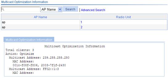
Table 23 Field description
|
Field |
Description |
|
AP Name |
Name of the AP. |
|
Radio ID |
ID of the radio with which the clients are associated. |
|
Total Clients |
Total number of clients served by multicast optimization. If a client joins multiple multicast groups, the client is counted as multiple clients. For example, if a client has joined two multicast groups through a radio, the client is counted as two clients by multicast optimization. |
|
Action |
Operating status of the multicast optimization function: · Optimize—The multicast optimization function is operating. · Halt—The multicast optimization function has been halted. |
|
Multicast Address |
Address of the multicast group that the clients have joined. |
|
MAC Address |
MAC addresses of the clients that have joined the multicast group. |
Configuring a guest access tunnel
After you complete the configuration, the aggregation AC and edge AC communicate with each other by following these steps:
1. The edge AC sends a keep-alive request to the aggregation AC.
2. Upon receiving the request, the aggregation AC determines whether the source IP address of the request belongs to one of the edge ACs configured on it. If it does, the aggregation AC sends a response and a guest access tunnel is established.
3. The edge AC sends keep-alive requests to the aggregation AC at a specific interval.
¡ If the edge AC does not receive any responses from the aggregation AC after three successive attempts, the edge AC terminates the guest access tunnel.
¡ If the aggregation AC does not receive any keep-alive requests three times the interval, it terminates the guest access tunnel.
Configuration restrictions and guidelines
When you configure a guest access tunnel, follow these restrictions and guidelines:
· If there are multiple guest access tunnels, each of them must belong to a different VLAN.
· The device supports at most 512 guest access tunnels. You can only establish a guest access tunnel with IPv4 addresses.
· Configure the same guest VLAN on both the edge AC and the aggregation ACs. For example, if you configure VLAN 1, VLAN 2, VLAN 3, and VLAN 4 on the edge AC, and configure VLAN 2 and VLAN 3 on the aggregation AC, you must configure VLAN 2 or VLAN 3 as the guest VLAN.
VLANs that can be configured as guest VLANs include:
¡ VLAN specified by the WLAN-ESS interface.
¡ VLANs specified when you bind a service template.
¡ VLANs assigned by the VLAN pool.
¡ VLANs authorized by the authentication server.
The priorities of these VLANs are in ascending order. A VLAN specified when you bind a service template and a VLAN assigned by the VLAN pool have the same priority.
Configuring the edge AC
1. Select Advanced > Guest Tunnel from the navigation tree.
Figure 44 Configuring the edge AC
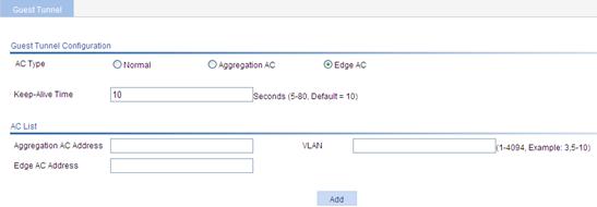
2. On the page that appears, select Edge AC and configure the parameters as shown in Table 24.
3. Click Add.
4. Click Apply.
|
Item |
Description |
|
Keep-Alive Time |
Specify the interval at which the edge AC sends keep-alive requests to aggregation ACs. |
|
Aggregation AC Address |
Specify the IPv4 address of the aggregation AC to be configured on the edge AC. |
|
VLAN |
Specify a guest VLAN name. |
|
Edge AC Address |
Specify the source IPv4 address for the edge AC to establish guest access tunnels with aggregation ACs. |
|
|
NOTE: · An edge AC can establish guest access tunnels with multiple aggregation ACs, but it cannot use different IP addresses to establish tunnels with one aggregation AC. · If several IP addresses configured on the edge AC belong to one aggregation AC, the aggregation AC uses the destination IP address of the first keep-alive request to establish a guest access tunnel with the edge AC. |
Configuring the aggregation AC
1. Select Advanced > Guest Tunnel from the navigation tree.
Figure 45 Configuring the aggregation AC

2. On the page that appears, select Aggregation AC and configure the parameters as shown in Table 25.
3. Click Add.
4. Click Apply.
|
Item |
Description |
|
Edge AC Address |
Specify the IP address of the edge AC to be configured on the aggregation AC. |
|
VLAN |
Specify a guest VLAN by its name. |
Viewing guest access tunnels
Select Advanced > Guest Tunnel from the navigation tree.
Figure 46 Guest access tunnel list
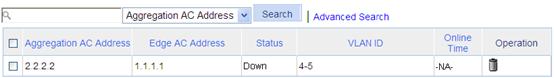
You can view the configurations and status of guest access tunnels on the current AC. The VLAN ID field shows configured guest VLANs.
Configuring Bonjour gateway
The AC supports centralized forwarding, local forwarding, and policy-based forwarding when it operates as a Bonjour gateway.
Enable multicast optimization on the Bonjour gateway for media traffic services such as video and audio.
Enabling Bonjour gateway
1. Select Advanced > Bonjour Gateway from the navigation tree.
Figure 47 Enabling Bonjour gateway

2. On the page that appears, select Bonjour Gateway and configure the parameters as shown in Table 26.
3. Click Apply.
|
Item |
Description |
|
Bonjour Gateway |
· Disable—Disable Bonjour gateway globally. · Enable—Enable Bonjour gateway globally. By default, Bonjour gateway is disabled globally. Bonjour gateway takes effect only after you enable it both globally and for an AP. You can enable Bonjour gateway for the AP on the AP > AP Setup or AP > AP Group page. |
|
Service Query |
· Disable—Disable active query for Bonjour services on the AC. · Enable—Enable active query for Bonjour services on the AC. By default, active query for Bonjour services is disabled on the AC. With this function enabled, the AC sends queries for a Bonjour service at the specified intervals and updates the service entry based on the responses. If no response is received within the TTL of the Bonjour service, the AC deletes the entry for the service. |
|
Query Interval |
Interval at which the AC sends queries for a service. |
|
Unicast to Multicast Threshold |
The AC can send unicast or multicast responses to clients in Bonjour service advertisement snooping. When the AC sends a multicast response to clients, it converts the multicast response to multiple unicast responses by default. This function prevents the AC from sending excessive unicast responses to clients. When this function is enabled, the AC sends one multicast response instead of multiple unicast responses to clients when the following conditions are met: · The clients are associated with the same BSS. · The clients query for the same service. · The number of clients meeting the above conditions reaches the threshold within 500 ms. |
Configuring a Bonjour policy
A service policy contains service type configuration and VLAN configuration.
The AC forwards queries and responses according to the following rules:
· For a query, if the service type in the query does not match the specified service type, the AC discards the query.
· For a response, the AC forwards it only when it matches service type, IP address, and instance name.
· The AC can forward queries and responses only to the VLANs in the configured VLAN lists.
|
|
NOTE: If a service uses multiple protocols, you must configure multiple service types on the AC to enable the AC to forward queries for the service. For example, you must configure both ipp and ipps service types on the AC for the airprint service. |
To configure a Bonjour policy:
1. Select Advanced > Bonjour Gateway from the navigation tree.
2. On the page that appears, select Bonjour Policy and click Add.
Figure 48 Configuring a Bonjour policy
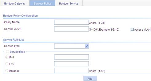
3. Configure the Bonjour policy parameters as shown in Table 27.
4. Click Add.
5. Click Apply.
|
Item |
Description |
|
Policy Name |
Configure a name for the Bonjour policy. By default, no Bonjour policy exists. You can configure up to 1000 Bonjour policies. |
|
Service VLAN |
Configure the VLANs to which the AC can forward queries and responses. By default, the AC cannot forward queries and responses. |
|
Access VLAN |
Allow the AC to forward queries and responses to the VLANs to which the clients belong. By default, the AC cannot forward queries and responses. |
|
Service Rule List |
|
|
Service Type |
Specify the type of service that can be queried by clients. Table 28 lists some Bonjour protocols by their names and service type strings. |
|
Service Rule |
· IPv4—Specify the IP address of the service that can be queried by clients. · IPv6—Specify the IPv6 address of the service that can be queried by clients. · Instance—Specify the instance name of the service that can be queried by clients. An instance name uniquely identifies a service. By default, clients can query all services. |
Table 28 Apple Bonjour protocols and service type strings
|
Service type |
Protocol name |
|
afpovertcp |
AppleTalkFiling Protocol |
|
airplay |
Airplay |
|
airport |
Airport Base Station |
|
apple-sasl |
Apple Password Server |
|
daap |
Digital Audio Access Protocol |
|
dacp |
Digital Audio Control Protocol |
|
distcc |
Distributed Compiler |
|
dpap |
Digital Photo Access Protocol |
|
eppc |
Remote AppleEvents |
|
ftp |
File Transfer Protocol |
|
http |
Hypertext Transfer Protocol |
|
Ica-networking |
Image Capture Sharing |
|
ichat |
iChat Instant Messaging Protocol |
|
ipp |
Internet Printing Protocol |
|
ipps |
Internet Printing Protocol |
|
nfs |
Network File System |
|
pdl-stream |
PDL Data Stream |
|
printer |
Line Printer Daemon |
|
raop |
Remote Audio Output Protocol |
|
riousbprint |
Remote I/O USB Printer Protocol |
|
servermgr |
Server Admin |
|
ssh |
Secure Shell |
|
telnet |
Remote Login |
|
webdav |
WebDav File System |
|
workstation |
Workgroup Manager |
|
xserveraid |
Xerver RAID |
Applying a Bonjour policy
You can apply a Bonjour policy on the Wireless Service > Access Service, AP > AP Setup, AP > AP group, and Authentication > User pages. If you apply a Bonjour policy to an AP group, the Bonjour policy takes effect on all APs in the AP group. If you apply different Bonjour policies to a user profile, an AP, and a service template, all Bonjour policies take effect on all views.
Assume that you apply Bonjour policies A and B to AP 1 and service template with the SSID service to allow the AC to forward queries and responses to VLAN A and VLAN B, respectively. When a client is associated with AP 1 through the SSID service, the AC forwards the queries and responses it receives to both VLAN A and VLAN B.
Viewing information about Bonjour services discovered by the AC
1. Select Advanced > Bonjour Gateway from the navigation tree.
2. On the page that appears, select Bonjour Service.
Figure 49 Viewing information about Bonjour services discovered by the AC
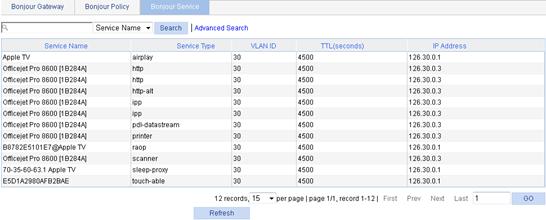
Configuring a Hotspot2.0 policy
Hotspot 2.0 does not take effect when local forwarding is enabled.
Creating a Hotspot2.0 policy
1. Select Advanced > Hotspot2.0 Service from the navigation tree.
2. On the page that appears, click Add.
Figure 50 Creating a Hotspot2.0 policy

3. Enter a name for the Hotspot2.0 policy.
4. Click Apply.
Configuring automatic network discovery
This feature enables clients to discover WAN link information, service provider information, and AP venue information through GAS frames sent by the AC.
To configure automatic network discovery:
1. Click the ![]() icon for the
target Hotspot2.0 policy.
icon for the
target Hotspot2.0 policy.
Figure 51 Configuring automatic network discovery
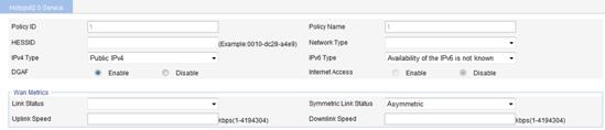
2. On the page that appears, configure the automatic network discovery parameters.
3. Click Apply.
To configure AP venue information:
1. Select AP > AP Setup from the navigation tree.
2. Click the ![]() icon for the target
AP.
icon for the target
AP.
3. On the page that appears, expand the Advanced Setup area.
4. In the AP Venue List area, configure AP venue information.
Figure 52 Configuring AP venue information
5. Click Add.
6. Click Apply.
Disabling the DGAF function
When the DGAF function is enabled for an AP, the AP forwards all downstream wireless broadcast ARP packets and wireless multicast packets. To prevent spoofing attacks by using downstream multicasts, you can disable the DGAF function for the AP.
To avoid packet loss, H3C recommends that you enable proxy ARP and multicast optimization before disabling this function.
Configuring network management parameters
1. Click the ![]() icon for the
target Hotspot2.0 policy.
icon for the
target Hotspot2.0 policy.
Figure 53 Configuring network management parameters
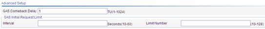
2. On the page that appears, configure the network management parameters as shown in Table 29.
3. Click Apply.
|
Item |
Description |
|
|
GAS Comeback Delay |
Configure the delay time for the clients to send GAS comeback frames. By default, the GAS comeback delay is 1 TU. |
|
|
GAS Initial Request Limit |
Interval |
Configure the maximum number of GAS initial frames the AC can receive from clients within the specified interval. Excessive GAS initial frames are discarded. By default, the number of GAS initial frames the AC can receive is not restricted. |
|
Limit Number |
||
Binding a Hotspot2.0 policy to a wireless service
Follow these restrictions and guidelines when you apply a Hotspot 2.0 policy:
· A Hotspot 2.0 policy can only be applied to a service template with the WPA encryption method and 802.1X authentication type. H3C recommends that you use the WPA2 encryption method on the service template.
· H3C recommends that you enable flood attack detection on the Security > WIDS page.
· The configurations and AP venue information for a Hotspot2.0 policy take effect only when the Hotspot2.0 policy is bound to a wireless service.
To bind a Hotspot2.0 policy to a wireless service:
1. Select Wireless Service > Access Service from the navigation tree.
2. Click the ![]() icon for the
target wireless service.
icon for the
target wireless service.
Figure 54 Binding a Hotspot2.0 policy to a wireless service
![]()
3. On the page that appears, select a Hotspot2.0 policy from the Bind Hotspot2.0 Policy list.
4. Click Apply.
Advanced settings configuration examples
1+1 fast backup configuration example
Network requirements
As shown in Figure 55, AC 1 and AC 2 back up each other, with AC 1 acting as the active AC. When the active AC fails, the standby AC takes over to provide services, ensuring no service interruption.
· Assign a higher priority to the AP connection to AC 1 (which is 6 in this example) to make sure AP will first establish a connection with AC 1. In this way, AC 1 acts as the active AC.
· When AC 1 is down, AC 2 becomes the new active AC.
· When AC 1 recovers, no switchover to AC 1 occurs, in which case AC 2 remains the active AC, and AC 1 acts as the standby AC. This is because the AP connection on AC 1 does not have the highest priority.

Configuration guidelines
· The wireless services configured on the two ACs should be consistent.
· Specify the IP address of the backup AC on each AC.
· AC backup has no relation to the access authentication method. However, the authentication method of the two ACs must be the same.
Configuring AC 1
1. Configure AP to establish a connection between AC 1 and AP. For more information about configurations, see "Configuring access services."
2. Select AP > AP Setup from the navigation tree.
3. Click the icon ![]() for the target AP.
for the target AP.
4. Expand Advanced Setup.
5. Set the connection priority to 6.
6. Click Apply.
Figure 56 Configuring the AP connection priority
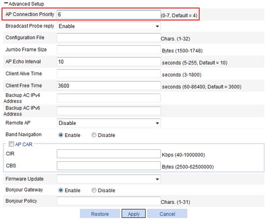
7. Select Advance > AC Backup from the navigation tree. You are placed on the Setup tab.
8. On the page that appears, select the IPv4 box, set the IP address of the backup AC to 1.1.1.5, and select enable to enable the fast backup mode.
9. Click Apply.
Figure 57 Configuring the IP address of the backup AC

Configuring AC 2
1. Configure AP to establish a connection between AC 2 and AP.
For more information about configurations, see "Configuring access services."
2. Leave the default value of the AP connection priority unchanged. (Details not shown.)
3. Select Advanced > AC Backup from the navigation tree.
4. On the page that appears, select the IPv4 box, set the address of the backup AC to 1.1.1.4, and select enable to enable the fast backup mode.
5. Click Apply.
Figure 58 Configuring the address of the backup AC
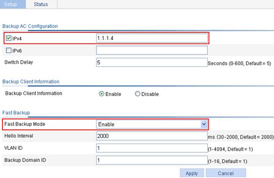
Verifying the configuration
1. When AC 1 operates correctly, view the AP status on AC 1 and AC 2. The AP connection priority on AC 1 is set to 6 (the higher one), so AC 1 becomes the active AC. The AP establishes a connection to AC 1 based on priority.
a. On AC 1, select Advanced > AC Backup from the navigation tree.
b. Click the Status tab.
The status information shows that AC 1 is the active AC.
Figure 59 Displaying the AP status on AC 1
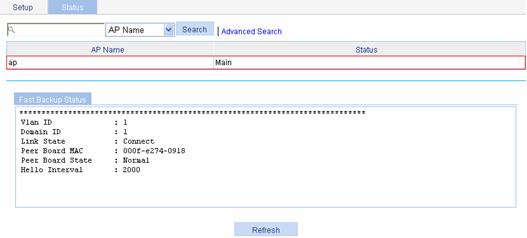
c. On AC 2, select Advanced > AC Backup from the navigation tree.
d. Click the Status tab.
The information shows that AC 1 is acting as the standby AC.
Figure 60 Displaying the AP status on AC 2

2. When AC 1 goes down, the standby AC (AC 2) detects the failure immediately through the heartbeat detection mechanism. Then AC 2 takes over to become the new active AC, providing services to AP.
¡ On AC 2 (the new active AC), display the AP status. (Details not shown.)
The information shows that AC 2 has become the active AC.
¡ On AC 2, display the client information. (Details not shown.)
The value for the State field turns to Running from Running/B, which indicates that the client is connecting to AC 2 through an active link.
3. When AC 1 recovers, AC 2 still acts as the active AC, and AC 1 becomes the standby AC. AC 1 establishes a backup link with the AP and backs up the client status.
1+N backup configuration example
Network requirements
As shown in Figure 61, AC 1 and AC 2 are active ACs, and AC 3 acts as the standby AC. When an active AC fails, AC 3 (the standby AC) takes over to provide services. As soon as the active AC recovers, the AP connects to the original active AC again.
· AP connects to AC 1, AC 2, and AC 3 through a Layer 2 switch. The IP addresses of AC 1, AC 2, and AC 3 are 1.1.1.3, 1.1.1.4, and 1.1.1.5, respectively.
· Assign the highest AP connection priority of 7 on AC 1 and AC 2 to make sure AP 1 establishes a connection with AC 1, and that AP 2 establishes a connection with AC 2.
· If one of the two active AC is down, AC 3 becomes the new active AC.
· When the faulty AC recovers, the AP that connects to AC 3 automatically connects to the original active AC. This is because the AP connection priority on the active AC has the highest priority. In this way, AC 3 can always act as a dedicated standby AC to provide backup services for AC 1 and AC 2.
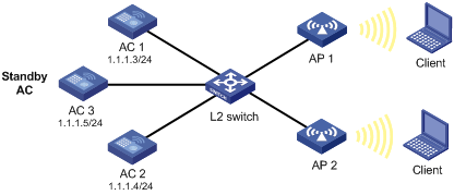
Configuring AC 1
1. Configure AC 1 so that a connection is set up between AC 1 and AP 1.
For more information about configurations, see "Configuring access services."
2. Select AP > AP Setup from the navigation tree.
3. Click the icon ![]() for the target AP.
for the target AP.
4. Expand Advanced Setup.
5. Set the connection priority to 7.
6. Click Apply.
Figure 62 Configuring the AP connection priority for AP 1
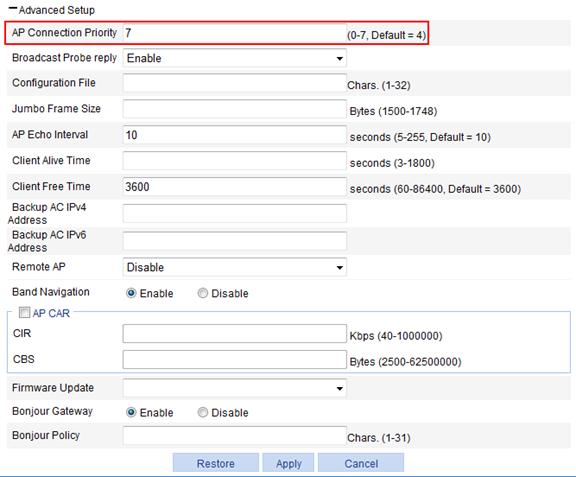
Configuring AC 2
1. Configure AC 2 so that a connection is set up between AC 2 and AP 2.
For more information about configurations, see "Configuring access services."
2. Set the AP connection priority to 7.
The configuration steps are the same as the steps on AC 1 (Details not shown.).
3. Configure AC 3 (the backup AC):
a. Configure the related information for AP 1 and AP 2.
For more information about configurations, see "Configuring access services."
b. Select AP > AP Setup from the navigation tree.
c. Click the ![]() icon for the target AP.
icon for the target AP.
d. Expand Advanced Setup.
e. Enter 1.1.1.3 in the Backup AC IPv4 Address field.
f. Click Apply.
Figure 63 Backing up the IP address of AC 1
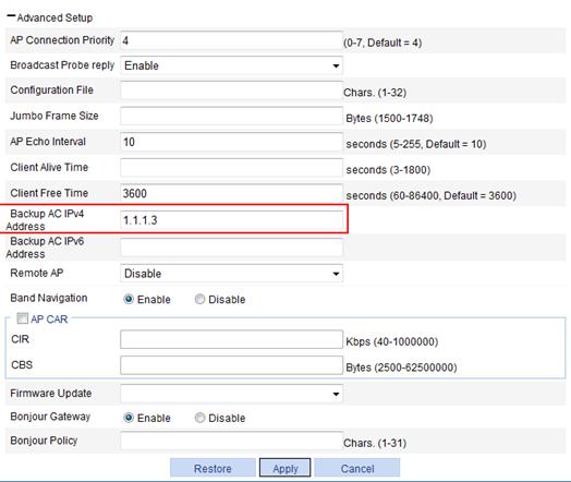
g. Select AP > AP Setup from the navigation tree.
h. Click the icon ![]() for the target AP.
for the target AP.
i. Expand Advanced Setup.
j. Enter 1.1.1.4 in the Backup AC IPv4 Address field.
k. Click Apply.
Figure 64 Backing up the IP address of AC 2
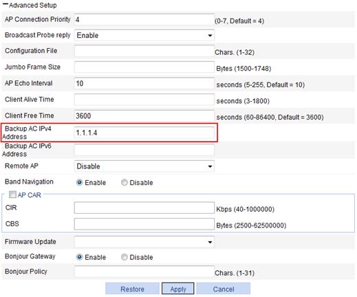
Verifying the configuration
1. When AC 1 goes down, AC 3 becomes the new active AC.
2. When AC 1 recovers, the AP connecting to AC 3 connects to AC 1 again. This is because the highest AP connection priority of 7 on AC 1 ensures an automatic switchover.
Client information backup configuration example
Network requirements
As shown in Figure 65, AC 1 and AC 2 support stateful failover. AC 1 is the primary AC. Enable client information backup on the two ACs so the clients can communicate during a primary/backup switchover. The client in this example is a client that uses clear-type service template for accessing the network.
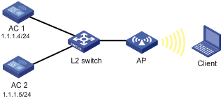
Configuration procedure
Complete the following configurations on both AC 1 and AC 2.
1. Build an IACTP tunnel. For more information, see "Configuring WLAN roaming."
2. Configure AC backup. For more information, see "Configuring 1+1 AC backup."
3. Configure client information backup:
a. Select Advanced > AC Backup from the navigation tree. You are placed on the Setup tab.
b. Click Enable to the right of Backup Client Information.
c. Click Apply.
Figure 66 Enabling client information backup
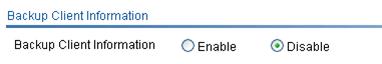
Verifying the configuration
1. When AC 1 operates correctly, display the client status on AC 1 and AC 2 to verify that the client has been associated with AC 1 through the AP, and the client information has been synchronized to AC 2.
a. Select Summary > Client from the navigation tree, click the Detail Information tab, and select the target client to view its detailed information.
Figure 67 Displaying the client status on AC 1

The page shows that the client is in Running status, which means the client is associated with the primary AC AC 1 because AC 1 has a higher connection priority.
b. Select Summary > Client from the navigation tree, click the Detail Information tab, and select the target client to view its detailed information.
Figure 68 Displaying the client status on AC 2
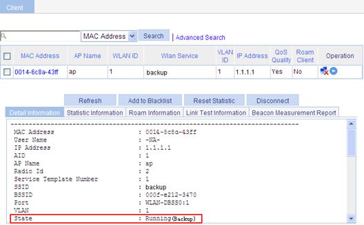
This page shows that the client is in Running(Backup) state, which means the client is associated with the backup AC AC 2.
c. Display roam-track information of the clients (select Summary > Client from the navigation tree, click the Roam Information tab, and select the target client to view its detailed roaming information. If the information on the two ACs is consistent, the client roaming information has been synchronized.
2. When AC 1 fails, AC 2 becomes the primary AC. During the switchover, clients are not logged off and can access network through AC 2.
AP-based session-mode load balancing configuration example
Network requirements
· As shown in Figure 69, all APs operate in 802.11g mode. Client 1 is associated with AP 1. Client 2 through Client 6 are associated with AP 2.
· Configure session-mode load balancing on the AC. The threshold (the maximum number of sessions) is 5, and the session gap is 4.
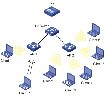
Configuration guidelines
An AP starts session-mode load balancing only when both the maximum sessions and maximum session gap are reached.
Configuration procedure
1. Before you configure load balancing, configure AP 1 and AP 2 on the AC to establish a connection between the AC and each AP.
For the related configuration, see "Configuring access services."
2. Configure session-mode load balancing:
a. Select Advanced > Load Balance from the navigation tree.
b. On the Load Balance tab, select the Session mode, enter the threshold 5, and use the default value for the gap.
c. Use the default values for Max Denial Count and RSSI Threshold.
d. Click Apply.
Figure 70 Setting session-mode load balancing
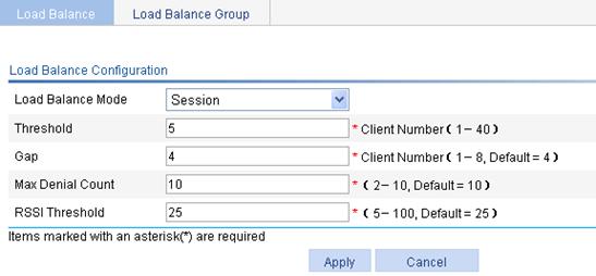
Verifying the configuration
Client 1 is associated with AP 1, and Client 2 through Client 6 are associated with AP 2. Because the number of clients associated with AP 1 reaches 5 and the session gap between AP 2 and AP 1 reaches 4, Client 7 is associated with AP 1.
AP-based traffic-mode load balancing configuration example
Network requirements
· As shown in Figure 71, all APs operate in 802.11g mode. Client 1 and Client 2 are associated with AP 1, and no client is associated with AP 2.
· Configure traffic-mode load balancing on the AC. The traffic threshold is 3 Mbps, which corresponds to the threshold value of 10 in percentage, and the traffic gap is 12 Mbps, which corresponds to the traffic gap value 40 in percentage.
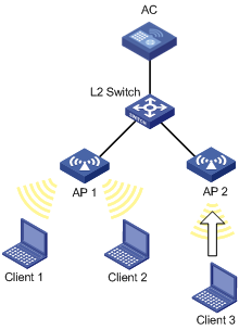
Configuration guidelines
An AP starts traffic-mode load balancing only when both the maximum traffic threshold and maximum traffic gap are reached.
Configuration procedure
1. Before you configure load balancing, configure AP 1 and AP 2 on the AC to establish a connection between the AC and each AP.
For the related configuration, see "Configuring access services."
2. Configure traffic-mode load balancing:
a. Select Advanced > Load Balance from the navigation tree.
b. On the Load Balance tab, select the Traffic mode, enter the threshold 10, and the traffic gap 40.
c. Use the default values for Max Denial Count and RSSI Threshold.
d. Click Apply.
Figure 72 Setting traffic-mode load balancing
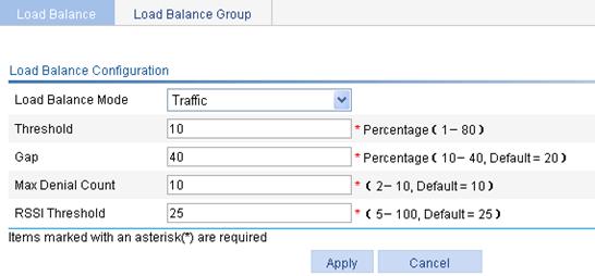
Verifying the configuration
Client 1 and Client 2 are associated with AP 1. Add Client 3 to the network. When the maximum traffic threshold and traffic gap are reached on AP 1, Client 3 is associated with AP 2.
Group-based session-mode load balancing configuration example
Network requirements
· As shown in Figure 73, all APs operate in 802.11g mode. Client 1 is associated with AP 1. Client 2 through Client 6 are associated with AP 2, and no client is associated with AP 3.
· Configure session-mode load balancing on the AC. The maximum number of sessions is 5, and the maximum session gap is 4.
· Session-mode load balancing is required on only radio 2 of AP 1 and radio 2 of AP 2. Therefore, add them to a load balancing group.

Configuration procedure
1. Before you configure load balancing, configure AP 1 and AP 2 on the AC to establish a connection between the AC and each AP.
For the related configuration, see "Configuring access services."
2. Configure load balancing:
a. Select Advanced > Load Balance from the navigation tree.
b. On the Load Balance tab, select Session from the Load Balance Mode list, enter the threshold 5, and use the default value for the gap.
c. Use the default values for Max Denial Count and RSSI Threshold.
d. Click Apply.
Figure 74 Configuring session-mode load balancing

3. Configure a load balancing group:
a. Select Advanced > Load Balance from the navigation tree.
b. Click the Load Balance Group tab.
c. Click Add.
d. On the page that appears, select ap1. radio 2 and ap2. radio 2 in the Radios Available area, click << to add them to the Radios Selected area, and click Apply.
Figure 75 Configuring a load balancing group

Verifying the configuration
· Radio 2 of AP 1 and radio 2 of AP 2 are in the same load balancing group. The radio of AP 3 does not belong to any load balancing groups. Because load balancing takes effect only on radios in a load balancing group, AP 3 does not take part in load balancing.
· Assume Client 7 wants to associate with AP 2. The number of clients associated with radio 2 of AP 2 reaches 5 and the session gap between radio 2 of AP 2 and AP 1 reaches 4, so Client 7 is associated with AP 1.
Group-based traffic-mode load balancing configuration example
Network requirements
· As shown in Figure 76, all APs operate in 802.11g mode. Client 1 and Client 2 are associated with AP 1, and no client is associated with AP 2 and AP 3.
· Configure traffic-mode load balancing on the AC. The maximum traffic threshold is 10%, and the maximum traffic gap is 20%.
· Traffic-mode load balancing is required only on radio 2 of AP 1 and radio 2 of AP 2. Therefore, add them to a load balancing group.
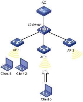
Configuration procedure
1. Before you configure load balancing, configure AP 1 and AP 2 on the AC to establish a connection between the AC and each AP.
For the related configuration, see "Configuring access services."
2. Configure load balancing:
a. Select Advanced > Load Balance from the navigation tree.
b. On the Load Balance tab, select Traffic from the Load Balance Mode list, enter the threshold 10 and the gap 40.
c. Use the default values for Max Denial Count and RSSI Threshold.
d. Click Apply.
Figure 77 Configuring traffic load balancing
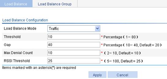
3. Configure a load balancing group:
a. Select Advanced > Load Balance from the navigation tree.
b. Click the Load Balance Group tab.
c. Click Add.
d. On the page that appears, select ap1. radio 2 and ap2. radio 2 in the Radios Available area, click << to add them to the Radios Selected area, and click Apply.
Figure 78 Configuring a load balancing group

Verifying the configuration
· Radio 2 of AP 1 and radio 2 of AP 2 are in the same load balancing group, and the radio of AP 3 does not belong to any load balancing groups. Because load balancing takes effect only on radios in a load balancing group, AP 3 does not take part in load balancing.
· Assume Client 3 wants to associate with AP 1. Because the maximum traffic threshold and traffic gap have been reached on radio 2 of AP 1, Client 3 is associated with AP 2.
AP version upgrade configuration example
Network requirements
As shown in Figure 79, configure the AP version upgrade function to upgrade the AC, AP 1 and AP 2. The AC has established an LWAPP tunnel with AP 1, AP 2 and AP 3, respectively.
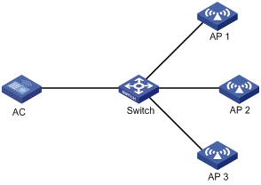
Configuration procedures
Before the configuration, assume that you have configured the three APs in AP > AP Setup.
1. Configure an AP group:
a. Select AP > AP Group from the navigation tree.
b. On the page that appears, click Add to create an AP group named update.
2. Enable the AP version upgrade function for AP 1 and AP 2:
a. Select ap1 and ap2 from the AP List, click
the ![]() icon
and add these two APs to the Selected AP List.
icon
and add these two APs to the Selected AP List.
b. Select Enable from the Firmware Update list.
c. Click Apply.
Figure 80 Configuring AP version upgrade (1)

3. Disable the AP version upgrade function for AP 3:
a. Select AP > AP Setup from the navigation tree.
b. Click the ![]() icon for AP 3.
icon for AP 3.
c. Select Disable from the Firmware Update list.
d. Click Apply.
Figure 81 Configuring AP version upgrade (2)

4. Download the AP version to the AC. (Details not shown.)
5. Upgrade the AC's version to B108D001 and reset the AC. AP 1 and AP 2 will try to establish tunnels with the AC of the new version:
¡ AP 1 and AP 2 compare their versions with that the version of the AC, download the AP version B108D001 from the AC and restart. After reboot, they use version B108D001 to establish LWAPP tunnels with the AC.
¡ AP 3 does not compare its version with the AC, and uses version B106D001 to establish an LWAPP tunnel with the AC.
Verifying the configuration
1. Select Summary > AP from the navigation tree.
2. On the page that appears, click the Detail tab, and click the target AP name.
You can see that versions of AP 1 and AP 2 are B108D001, and the version of AP 3 remains as B106D001.
Wireless location configuration example
Network requirements
As shown in Figure 82, AP 1, AP 2, and AP 3 operate in normal mode. They send the collected tag and MU messages to an AE (the location server), which performs location calculation and then sends the data to the graphics software. You can obtain the location information of the rogue AP, APs, and clients by using maps, forms or reports.
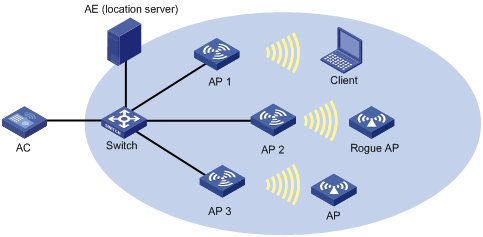
Configuration guidelines
Before you enable the wireless location function, make sure at least three APs operate in normal mode, bind the APs to a wireless service, and enable the wireless service so that the APs can detect Tags and clients not associated with them, and that the AE can implement location calculation.
Configuring the AE
1. Configure the IP addresses of AP 1, AP 2, and AP 3 on the AE, or select the broadcasting mode for the AE to discover APs.
2. Perform configuration related to wireless location on the AE.
Configuring AP 1
AP 1, AP 2, and AP 3 are configured similarly, and the following only describes how to configure AP 1 for illustration.
To bind the wireless service to AP 1:
1. Select AP > AP Setup from the navigation tree.
2. Click Add.
3. On the page that appears, enter the AP name ap1, select the model WA3628i-AGN, select Manual from the Serial ID list, enter the AP serial ID in the field, and click Apply.
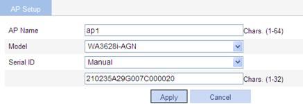
4. Select Wireless Service > Access Service from the navigation tree.
5. Click Add.
6. On the page that appears, specify the Wireless Service Name as service, select clear from the Wireless Service Type list, and click Apply.
Figure 84 Creating a wireless service
7. Select Wireless Service > Access Service from the navigation tree.
8. On the page that appears, select the box to the left of service.
9. Click Enable.
Figure 85 Enabling the wireless service

10. Select Wireless Service > Access Service from the navigation tree.
11. On the page that appears, click the ![]() icon for
wireless service service.
icon for
wireless service service.
12. Select the box to the left of 802.11n(2.4GHz).
13. Click Bind.
Figure 86 Binding the wireless service to a radio
Enabling 802.11n
1. Select Radio > Radio from the navigation tree.
2. Select the target AP.
3. Click Enable.
Figure 87 Enabling 802.11n (2.4 GHz)

Enabling wireless location
1. Select Advanced > Wireless Location from the navigation tree.
2. On the page that appears, perform the following tasks:
a. Select Enable for Location Function.
b. Select Aero Scout for Protocol Type.
c. Select Dynamic for Address Acquisition Method.
d. Select Tag Mode and MU Mode for ap1, ap2, and ap3.
3. Click Apply.
Figure 88 Enabling wireless location
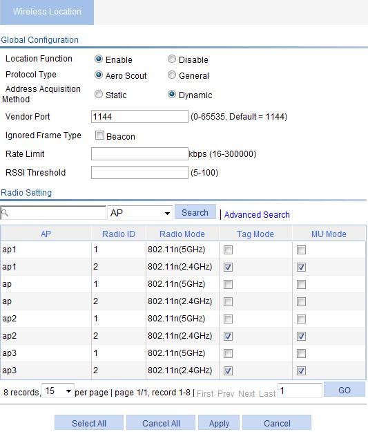
Verifying the configuration
You can display the location information of the rogue AP, APs, and clients by using maps, forms or reports.
Wireless sniffer configuration example
Network requirements
As shown in Figure 89, configure a Capture AP, and enable wireless sniffer on this AP to capture wireless packets. The captured packets are then saved in a .dmp file for troubleshooting.
Configuring Capture_AP
1. Select AP > AP Setup from the navigation tree.
2. Click Add.
3. On the page that appears, enter the AP name capture_ap, select the model WA3628i-AGN, select Manual from the Serial ID list, enter the AP serial ID in the field, and click Apply.
Figure 90 Creating a Capture AP
4. Select Radio > Radio from the navigation tree.
5. Click the ![]() icon of 802.11n(2.4 GHz) for the Capture_AP.
icon of 802.11n(2.4 GHz) for the Capture_AP.
6. Select 6 from the Channel list.
7. Click Apply.
8. Select Radio > Radio from the navigation tree.
9. Select the target AP.
10. Click Enable.
Figure 92 Enabling 802.11n (2.4 GHz)

Configuring and enabling wireless sniffer
1. Select Advanced > Wireless Sniffer from the navigation tree.
2. On the page that appears, enter the capture limit 5000, enter the file name CapFile, and click Apply.
3. Click the ![]() icon for radio 802.11g.
icon for radio 802.11g.
Figure 93 Configuring and enabling wireless sniffer
Verifying the configuration
· Capture AP captures wireless packets and saves the packets to a CAP file in the default storage medium. Administrators can download the file to the PC and get the packet information by using tools such as Ethereal.
· When the total number of captured packets reaches the upper limit, Capture AP stops capturing packets.
AP provision configuration example
Network requirements
Configure AP provision on AC 1 to assign the following network settings to AP 1 and AP 2:
· IP address 2.2.2.1/24 for AC 1 so that AP 1 and AP 2 can discover AC 1.
· IP address 1.1.1.1/24 for AP 1 and IP address 1.1.1.2/24 for AP 2.
· Username test and password test for AP 1 and AP 2 when they operate as 802.1X clients.
· Authentication method peap-mschapv2.
· 802.1X client function for Ethernet interfaces on AP 1 and AP 2.
Figure 94 Network diagram
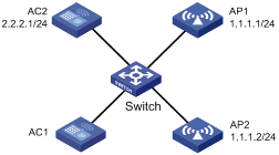
Configuring AC 1
Make sure AP 1 and AP 2 have established connections to AC. Otherwise, AC 1 cannot assign the network settings to them.
1. Configure global provision information so that AP 1 and AP 2 can discover AC 2 with IP address 2.2.2.1:
a. Select Advanced > AP Provision from the navigation tree.
b. Click the Global Provision tab.
c. Enter IP address 2.2.2.1 in the AC IPv4 Address field.
d. Click Apply.
Figure 95 Configuring global provision
2. Configure AP 1 and AP 2 as provision APs:
a. Select Advanced > AP Provision from the navigation tree.
b. Click the Non Provision APs tab.
Figure 96 Configuring non provision APs

c. Select the boxes to the left of ap1 and ap2.
d. Click Change to Provision AP.
e. Click the Provision APs tab.
Figure 97 Configuring provision APs

f. Click the ![]() icon for ap1.
icon for ap1.
g. Assign the following network settings to AP 1:
- IPv4 address 1.1.1.1 and mask 24.
- 802.1X client function.
- Username test and password test.
- Authentication method peap-mschapv2.
h. Click Apply Provision.
Figure 98 Configuring AP provision information
i. Assign the following network settings to AP 2:
- IPv4 address 1.1.1.2 and mask 24.
- 802.1X client function.
- Username test and password test.
- Authentication method peap-mschapv2.
j. Click the Provision APs tab.
Figure 99 Configuring provision APs
k. Select the boxes to the left of ap1 and ap2.
l. Click Apply Provision.
Configuring AC 2
Configure wireless service on AC 2. For more information, see "Configuring access services."
Verifying the configuration
1. On AC 1, select Summary > AP from the navigation tree.
Figure 100 AP information page
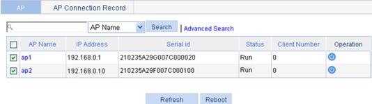
2. Select the boxes to the left of ap1 and ap2.
3. Click Reboot.
After restart, AP 1 and AP 2 establish connections to AC 1.
4. On AC 2, select Summary > AP from the navigation tree.
The two APs are both in Run status.
Figure 101 AP information page on AC 2
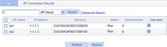
Band navigation configuration example
Network requirements
As shown in Figure 102, Client 1 through Client 4 try to associate with AP 1, and the two radios of AP 1 operate at 5 GHz and 2.4 GHz, respectively. Client 1, Client 2, and Client 3 are dual-band clients, and Client 4 is a single-band (2.4 GHz) client. Configure band navigation to direct clients to different radios of the AP.
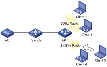
Configuring the AC
To enable band navigation to operate correctly, make sure of the following:
· The fast association function is disabled. By default, the fast association function is disabled.
· Band navigation is enabled for the AP. By default, band navigation is enabled for the AP.
1. Create an AP:
a. Select AP > AP Setup from the navigation tree.
b. Click New.
c. On the page that appears, enter the AP name ap 1, select the model WA3628i-AGN, select Manual from the Serial ID list, and enter the AP serial ID in the field.
d. Click Apply.
2. Configure wireless service:
a. Select Wireless Service > Access Service from the navigation tree.
b. Click Add.
c. On the page that appears, set the service name to band-navigation, select the wireless service type Clear, and click Apply.
3. Enable wireless service:
a. Select Wireless Service > Access Service from the navigation tree.
b. Set the band-navigation box.
c. Click Enable.
4. Bind an AP radio to the wireless service:
a. Select Wireless Service > Access Service from the navigation tree.
b. Click the ![]() icon for the
wireless service band-navigation.
icon for the
wireless service band-navigation.
c. Select the boxes next to ap1 with radio types 802.11n(2.4GHz) and 802.11n(5GHz).
d. Click Bind.
Figure 103 Binding an AP radio

5. Enable 802.11n(2.4GHz) and 802.11n(5GHz) radios:
a. Select Radio > Radio Setup from the navigation tree.
b. Select the boxes next to ap1 with the radio modes 802.11n(2.4GHz) and 802.11n(5GHz).
c. Click Enable.
6. Configure band navigation:
a. Select Advance > Band Navigation from the navigation tree.
b. On the page that appears, click Enable, and type the Session Threshold 2 and Gap 1. Use the default values for other options.
c. Click Apply.
Figure 104 Configuring band navigation
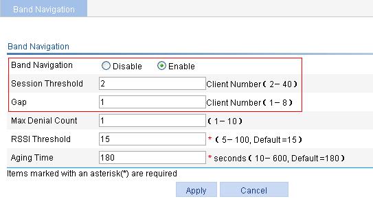
Verifying the configuration
Client 1 and Client 2 are associated with the 5 GHz radio of AP 1, and Client 4 can only be associated with the 2.4 GHz radio of AP 1. Because the number of clients on the 5 GHz radio has reached the upper limit 2, and the gap between the number of clients on the 5 GHz radio and 2.4 GHz radio has reached the session gap 1, Client 3 will be associated with the 2.4 GHz radio of AP 1.
BAS AC configuration example
Network requirements
BAS AC 1 can support up to 1024 APs, and BAS AC 2 can support up to 192 APs. Enable MAC-BAC so that the master AC assigns a BAS AC with the lowest workload (BAS AC 1) to the AP.
Figure 105 Network diagram
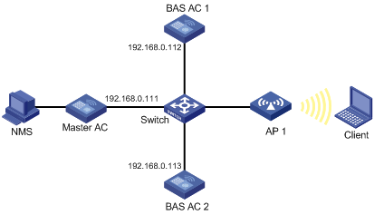
Configuring BAS AC 1
1. Configure parameters for BAS AC 1:
a. Select Advanced > BAS AC from the navigation tree.
b. Select Enable to the right of BAS AC Mode, enter 192.168.0.112 as the CAPWAP IPv4 Address, and enter 192.168.0.110 as the BAS AC IPv4 Address.
c. Click Apply.
Figure 106 Configuring BAS AC 1

2. Specify an IP address for the master AC:
# Specify the IP address of the master AC as 192.168.0.111.
<BAS AC1> system-view
[BAS AC1] wlan master-ac ip 192.168.0.111
3. Configure AP 1:
Configure AP 1 on BAS AC 1. For more information, see "Configuring access services."
Configuring BAS AC 2
1. Configure parameters for BAS AC 2:
a. Select Advanced > BAS AC from the navigation tree.
b. Select Enable to the right of BAS AC Mode, enter 192.168.0.113 as the CAPWAP IPv4 Address, and enter 192.168.0.114 as the BAS AC IPv4 Address.
c. Click Apply.
Figure 107 Configuring BAS AC 2
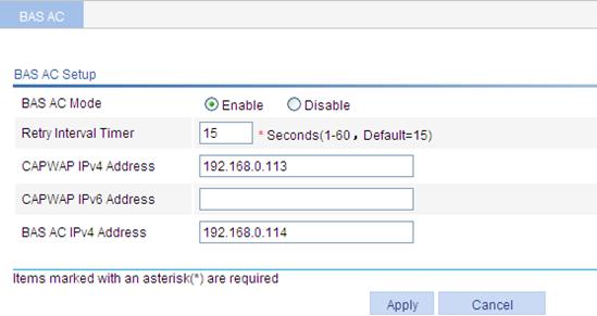
2. Specify an IP address for the master AC:
# Specify the IP address of the master AC as 192.168.0.111.
<BAS AC2> system-view
[BAS AC2] wlan master-ac ip 192.168.0.111
3. Configure AP 1:
Configure AP 1 on BAS AC 2. For more information, see "Configuring access services."
4. Configure the master AC:
Wireless devices do not support the master AC function. For more information about the master AC configuration, see relevant manuals.
VLAN pool configuration example
Network requirements
Configure a VLAN pool that contains VLANs 2 through 5 for the AP to assign clients to different VLANs.
Figure 108 Network diagram
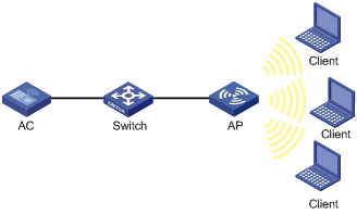
Configuring the AC
1. Create a VLAN pool:
a. Select Advanced > VLAN Pool from the navigation tree.
b. On the page that appears, set the VLAN pool name to office and set the VLAN list to 2-5.
c. Click Apply.
Figure 109 Creating a VLAN pool
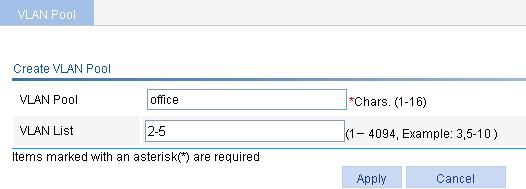
2. Create an AP:
a. Select AP > AP Setup from the navigation tree.
b. Click Add.
c. On the page that appears, enter the AP name ap, select the model WA3628i-AGN, select Manual from the Serial ID list, and enter the AP serial ID in the field.
d. Click Apply.
3. Configure wireless service:
a. Select Wireless Service > Access Service from the navigation tree.
b. Click Add.
c. On the page that appears, set the service name to office and select the wireless service type Clear. You are placed on the access service configuration page.
d. Enable MAC VLAN.
e. Click Apply.
Figure 110 Enabling MAC VLAN
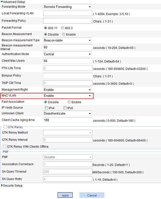
4. Enable wireless service:
a. Select Wireless Service > Access Service from the navigation tree.
b. Select the office box.
c. Click Enable.
5. Bind an AP radio to the wireless service:
a. Select Wireless Service > Access Service from the navigation tree.
b. Click the ![]() icon for the
wireless service office.
icon for the
wireless service office.
c. Select the box with radio type 802.11n(2.4GHz).
d. Select the Binding VLAN pool option and select the target VLAN pool from the Binding VLAN pool list.
e. Click Bind.
Figure 111 Binding a VLAN pool to a wireless service

6. Enable 802.11n(2.4GHz) radio:
a. Select Radio > Radio Setup from the navigation tree.
b. Select the box to the left of ap with the radio mode 802.11n(2.4GHz).
c. Click Enable.
Verifying the configuration
· Select Advanced > VLAN Pool from the navigation tree to display the number of clients in each VLAN in the VLAN pool.
· Select Summary > Client from the navigation tree, click Details, and click the target client to display the VLAN to which the client belongs.
Multicast optimization configuration example
Network requirements
As shown in Figure 112, enable multicast optimization for the AP to convert multicast packets to unicast packets for up to two clients.
Enable IGMP snooping on the AC before enabling multicast optimization and configure the aging time of multicast optimization entries to be greater than the aging time of IGMP snooping dynamic member ports.

Configuring the AC
1. Select Advanced > Multicast Optimization from the navigation tree.
2. Set the Aging Time to 300 seconds, the Multicast Optimization Max Clients to 2, and Max Client Limit Exceeded Action to Exclude New Clients for Multicast Optimization.
3. Click Apply.
4. Select the target wireless service.
5. Click Enable.
Figure 113 Configuring multicast optimization
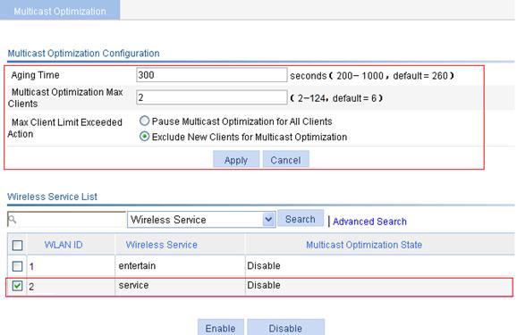
Verifying the configuration
Client 1 and Client 2 are associated with a radio of the AP. Because the number of clients on the radio has reached the upper limit 2, Client 3 cannot be added to multicast optimization entries.
Guest access tunnel configuration example
Network requirements
As shown in Figure 114, AC 1 is an edge AC and AC 2 is an aggregation AC. Configure a guest access tunnel so that guest traffic is separated from the traffic of the internal network. Guests get online through guest VLAN VLAN 5.

Configuring AC 1
Before configuring the edge AC, you need to finish the following configurations:
· Configure wireless services on AC 1. For more information, see "Configuring access services".
· Configure guest VLAN VLAN 5. (Details not shown.)
To configure AC 1:
1. Select Advanced > Guest Tunnel from the navigation tree.
2. On the page that appears, select Edge AC, enter 192.168.2.3 as the Aggregation AC Address, and enter 192.168.2.1 as the Edge AC Address. Specify VLAN 5 as the guest VLAN.
3. Click Add.
4. Click Apply.
Figure 115 Configuring the edge AC
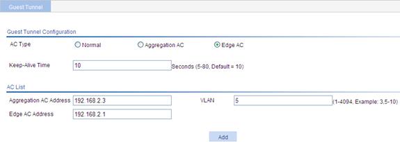
Configuring AC 2
1. Select Advanced > Guest Tunnel from the navigation tree.
2. On the page that appears, select Aggregation AC, enter 192.168.2.1 as the Aggregation AC Address, and specify VLAN 5 as the guest VLAN.
3. Click Add.
4. Click Apply.
Figure 116 Configuring the aggregation AC

Verifying the configuration
· Select Advanced > Guest Tunnel from the navigation tree. You can see that the guest access tunnel is in Up state.
· Select Summary > Client from the navigation tree. You can see that guests get online through VLAN 5.
Bonjour gateway configuration example
Network requirements
As shown in Figure 117, Apple TV, Print, iPad 1, and iPad 2 associate with the AP through service templates with SSIDs apple_tv, print, student, and teacher, respectively. Apple TV, Print, iPad 1, and iPad 2 belong to VLANs 3, 4, 10, and 20, respectively.
Configure Bonjour gateway to make sure iPad 2 can query the services of both Apple TV and Print and iPad 1 can only query the service of Print.

Configuration procedures
1. Configure wireless services on the AC. (Details not shown.)
2. Configure the DHCP server to assign an IP address of the AC as the gateway IP address of the clients. (Details not shown.)
3. Enable Bonjour gateway:
a. Select Advanced > Bonjour Gateway from the navigation tree, and click the Bonjour Gateway tab.
b. Select Enable for Bonjour Gateway.
c. Click Apply.
Figure 118 Enabling Bonjour gateway
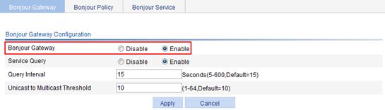
4. Configure Bonjour policy teacher:
a. Select Advanced > Bonjour Gateway from the navigation tree, and click the Bonjour Policy tab.
b. Click Add.
c. On the page that appears, specify the Policy Name as teacher and Service VLAN as 3-4.
d. Click Apply.
5. Configure Bonjour policy student in the same way Bonjour policy teacher is configured, and specify the service VLAN for Bonjour policy student as 4. (Details not shown.)
Figure 119 Configuring Bonjour policies
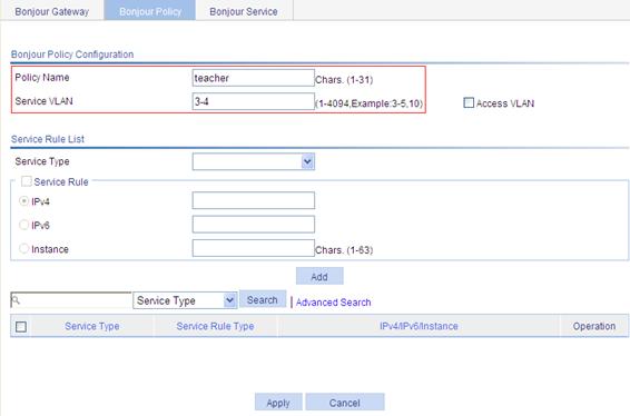
6. Apply Bonjour policy teacher:
a. Select Wireless Service
> Access Service from the navigation tree, and
click the ![]() icon for
wireless service teacher.
icon for
wireless service teacher.
b. Specify Bonjour Policy as teacher.
c. Click Apply.
7. Apply Bonjour policy student to wireless service student in the same way Bonjour policy teacher is applied to wireless service teacher. (Details not shown.)
Figure 120 Applying Bonjour policies
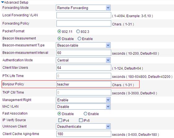
Verifying the configuration
1. Select Advanced > Bonjour Gateway from the navigation tree, and click the Bonjour Service tab.
You can see that the AC can discover the services of both Apple TV and Print.
2. Select Summary > Client from the navigation tree, and click the Detailed Information tab.
You can see that iPad 1 can discover only the service of Print and iPad 2 can discover the services of both Apple TV and Print.