- Table of Contents
-
- H3C Access Controllers Web-Based Configuration Guide(E3703P61 R2509P61 R3709P61 R2609P61 R3509P61)-6W103
- 00-Preface
- 01-About
- 02-Web overview
- 03-Login
- 04-Quick Start
- 05-Summary
- 06-Device
- 07-Network
- 08-AP Configuration
- 09-Wireless Service
- 10-WLAN Roaming Configuration
- 11-Radio Configuration
- 12-Authentication
- 13-Security
- 14-QoS Configuration
- 15-Advanced Settings
- 16-Stateful Failover Configuration
- 17-VPN
- 18-SSL VPN Configuration
- Related Documents
-
| Title | Size | Download |
|---|---|---|
| 10-WLAN Roaming Configuration | 679.58 KB |
Contents
Configuring an IACTP tunnel and WLAN roaming
Adding a member to the IACTP tunnel
WLAN roaming configuration examples
Intra-AC roaming configuration example
Inter-AC roaming configuration example
Configuring an IACTP tunnel and WLAN roaming
Support for this feature depends on the device model. For more information, see "About the H3C Access Controllers Web-Based Configuration Guide."
For a client to remain in the same VLAN during WLAN roaming, enable MAC VLAN.
IACTP tunnel
The Inter AC Tunneling Protocol (IACTP) is an H3C-proprietary protocol that provides a generic packet encapsulation and transport mechanism for ACs to securely communicate with each other.
IACTP provides a control tunnel to exchange control messages, and a data tunnel to transmit data packets between ACs. IACTP supports both IPv4 and IPv6.
WLAN roaming, AC backup, and AC-BAS collaboration must support IACTP for inter-AC communication.
WLAN roaming overview
WLAN roaming enables clients to roam between ACs in a mobility group or within an AC. ACs in a mobility group communicate with each other through IACTP tunnels.
When a client supporting fast roaming associates with one of the ACs in a mobility group for the first time, the AC (called the HA) performs 802.1X authentication and 11 Key exchange for the client. The client information is synchronized across ACs in the mobility group. When this client roams to another AC in the mobility group (called the FA), the FA uses stored client information to fast authenticate the client by skipping 802.1X authentication, and performing only 802.11 key exchange and associates with the client.
Configuring an IACTP tunnel
|
|
IMPORTANT: Roaming group configuration is available only for inter-AC roaming. For the configuration example of inter-AC roaming, see "Inter-AC roaming configuration example." |
1. Select Roam > Roam Group from the navigation tree.
Figure 1 Configuring an IACTP tunnel

2. Configure an IACTP tunnel as described in Table 1.
3. Click Apply.
|
Item |
Description |
|
IACTP Tunnel |
· Enable—Enable IACTP service. · Disable—Disable IACTP service. |
|
IP Type |
Select IPv4 or IPv6. |
|
Source Address |
Source address of the IACTP protocol. |
|
Auth Mode |
Optional. MD5: Select the MD5 authentication mode. The control message integrity can be verified when the MD5 authentication mode is selected. The sender (an AC) calculates a digest based on the content of a control message. On receiving such a message, the receiver (another AC in the roaming group) will calculate the digest again and compare it against the digest present in the message to verify the integrity of the packet received. If the digests are the same, the packet is not tampered. |
|
Auth Key |
MD5 authentication key. If you select the MD5 authentication mode, you need to input an authentication key. |
Adding a member to the IACTP tunnel
1. Select Roam > Roam Group from the navigation tree.
Figure 2 Adding a member to the IACTP tunnel
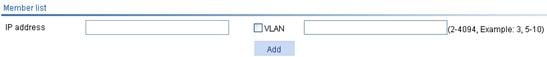
2. Add a member to the IACTP tunnel as described in Table 2.
3. Click Add.
4. Click Apply.
|
Item |
Description |
|
IP Address |
Add the IP address of an AC to a roaming group.
When you configure a roaming group, the roaming group name configured for the ACs in the same roaming group must be the same. |
|
VLAN |
Configure the VLAN to which the roaming group member belongs. This configuration item is optional. If multiple ACs exist in a roaming group, make sure no loop occurs on the IACTP tunnels between ACs in the group when configure this option. |
|
|
NOTE: · The user profile configurations of the ACs in a roaming group must be the same. For more information, see "Configuring users." |
Configuring WLAN roaming
Configuring WLAN roaming
1. Select Roam > Roam Group from the navigation tree.
Figure 3 Configuring WLAN roaming
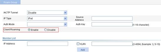
2. Select Enable to the right of Client Roaming.
By default, WLAN roaming is enabled.
3. Click Apply.
Displaying client information
1. Select Roam > Roam Client from the navigation tree.
Figure 4 Displaying client information

2. View the detailed information and roaming information of the client by clicking a target client. For more information, see "Displaying information summary."
WLAN roaming configuration examples
Intra-AC roaming configuration example
Network requirements
As shown in Figure 5, an AC has two APs associated and all of them are in VLAN 1. A client is associated with AP 1. Configure intra-AC roaming so that the client can associate with AP 2 when roaming to AP 2.

Configuration guidelines
When you configure intra-AC roaming, the SSIDs of the two APs must be the same. The same wireless service must be bound to the radios of the two APs in Bind AP radios to the wireless service.
Configuring the AC
If remote authentication is required in the authentication mode you select, configure the RADIUS server. For information about how to configure the RADIUS server, see "Configuring AAA."
1. Create two APs:
a. Select AP > AP Setup from the navigation tree.
b. Click Add.
c. On the page that appears, set the AP name to ap1, select the AP model WA3628i-AGN, select manual from the Serial ID list, enter the serial ID of the AP, and click Apply.
d. Follow the same steps to create the other AP.
2. Configure wireless service:
a. Select Wireless Service > Access Service from the navigation tree.
b. Click Add.
c. On the page that appears, set the service name to Roam, and click Apply.
|
|
NOTE: For information about how to configure the authentication mode, see "Configuring access services." Fast roaming can be implemented only when the RSN+802.1X authentication mode is adopted. |
3. Enable wireless service:
a. Select Wireless Service > Access Service from the navigation tree.
b. Select the Roam box.
c. Click Enable.
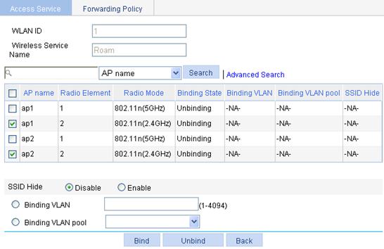
4. Bind AP radios to the wireless service:
a. Select Wireless Service > Access Service from the navigation tree.
b. Click the ![]() icon to the right of the wireless service Roam.
icon to the right of the wireless service Roam.
c. Select the box before ap1 with radio type 802.11n(2.4GHz), and the box to the left of ap2 with radio type 802.11n(2.4GHz).
d. Click Bind.
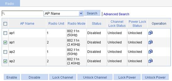
5. Enable dot11g radio:
a. Select Radio > Radio Setup from the navigation tree.
b. On the page that appears, select the box to the left of ap1 with the radio mode 802.11n(2.4GHz), and select the box to the left of ap2 with the radio mode 802.11n(2.4GHz).
c. Click Enable.
Verifying the configuration
1. Display the roaming information of the client:
a. Select Summary > Client from the navigation tree.
b. Click the Roam Information tab.
c. Click the desired client to view the roaming information of the client.
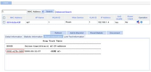
From the roaming information, you can see that the client accesses the WLAN through AP 1, and the BSSID of AP 1 is 000f-e27b-3d90 (see Figure 8.).
Figure 8 Client status before intra-AC roaming
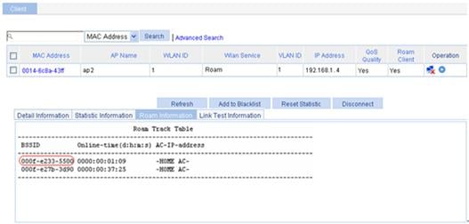
d. Click Refresh.
On the Roam Information page that appears, you can see that the client is connected to the WLAN through AP 2, and the BSSID of AP 2 is 000f-e233-5500.
Figure 9 Client status after intra-AC roaming
2. View the Roam Status field:
a. Select Summary > Client from the navigation tree.
You are placed in the Detail Information tab.
b. Click the desired client.
Intra-AC roam association appears in the Roam Status field.
Figure 10 Verifying intra-AC roaming

Inter-AC roaming configuration example
Network requirements
As shown in Figure 11, two ACs that each are connected to an AP are connected through a Layer 2 switch. Both ACs are in the same network. The IP address of AC 1 is 192.168.1.100 and that of AC 2 is 192.168.1.101 A client associates with AP 1.
Configure inter-AC roaming so that the client can associate with AP 2 when roaming to it.

Configuration guidelines
Follow these guidelines when you configure inter-AC roaming:
· The SSIDs and the authentication and encryption modes of two APs should be the same.
· An IACTP tunnel must be configured on both of the two ACs.
Configuring AC 1 and AC 2
If remote authentication is required in the authentication mode you select, configure the RADIUS server. For information about how to configure the RADIUS server, see "Configuring RADIUS."
1. Establish AC-AP connections:
Configure AC 1 and AC 2 to establish a connection between AP 1 and AC 1, and between AP 2 and AC 2. You see that the two APs are in the running status only after you establish the connections. To view the AP status, select Summary > AP or AP > AP Setup.
For the related configuration, see "Configuring access services."
|
|
NOTE: For the configuration of authentication mode, see "Configuring access services." Fast roaming supporting key caching can be implemented only when RSN+802.1X authentication is adopted. |
2. Configure an IACTP tunnel:
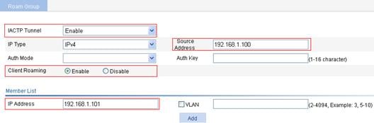
a. Select Roam > Roam Group from the navigation tree.
b. On the page that appears, select Enable from the IACTP Tunnel list, select IPv4 from the IP Type list, enter 192.168.1.100 for Source address, the IP address of AC 1, enter the IP address of AC 2 in the member list, and click Add.
c. Click Apply.
Figure 12 Configuring an IACTP tunnel on AC 1
d. Configure the IACTP tunnel on AC 2.
The source address is the IP address of AC 2, and the member address is the IP address of AC 1. (Details not shown.)
Verifying the configuration
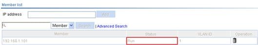
1. Verify the status of the IACTP tunnel:
a. On AC 1, select Roam > Roam Client from the navigation tree.
You can see that the group member 192.168.1.101 is in Run state.
Figure 13 Verifying the IACTP tunnel state (1)
b. On AC 2, select Roam > Roam Client from the navigation tree.
You can see that the group member 192.168.1.100 is in Run state.
Figure 14 Verifying the IACTP tunnel state (2)

2. Display the client information:
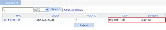
a. After the client roams from AP 1 to AP 2, select Roam > Roam Client on AC 1.
You can see that the client roams out of 192.168.1.100.
Figure 15 Viewing client information
b. Select Roam > Roam Client on AC 2.
You can see that the client roams in to 192.168.1.1.100.
3. View connection information about the client that is associated with the AP, and the Roam Status field in the client detailed information:
a. Before roaming, select Summary > Client from the navigation tree on AC 1.
You can see that the client is associated with AP 1.
b. After roaming: Select Summary > Client from the navigation tree on AC 1.
The client has roamed from AP 1 to AP 2, so no client information is displayed on the page.
c. Select Summary > Client from the navigation tree on AC 2.
You can view the client information.
d. Select the Detail Information tab, and then click the desired client.
Inter-AC roam association appears in the Roam Status field. This indicates that the client has roamed to AP 2.
Figure 16 Verifying inter-AC roaming

4. View the BSSID field:
a. Before roaming, select Summary > Client from the navigation tree on AC 1, select the Detail Information tab, and click the desired client to view the roaming information of the client.
The roaming information in Figure 17 shows that the client connects to the WLAN through AP 1, and the BSSID of AP 1 is 000f-e27b-3d90.
Figure 17 Client status before inter-AC roaming
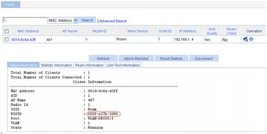
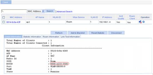
b. Select Summary > Client, from the navigation tree on AC 2, select the Detail Information tab, and click the desired client to view the roaming information of the client.
The roaming information in Figure 18 shows that the client connects to the WLAN through AP 2, and the BSSID of AP 2 is 000f-e233-5500.
Figure 18 Client status after intra-AC roaming