- Table of Contents
-
- H3C Access Controllers Web-Based Configuration Guide(E3703P61 R2509P61 R3709P61 R2609P61 R3509P61)-6W103
- 00-Preface
- 01-About
- 02-Web overview
- 03-Login
- 04-Quick Start
- 05-Summary
- 06-Device
- 07-Network
- 08-AP Configuration
- 09-Wireless Service
- 10-WLAN Roaming Configuration
- 11-Radio Configuration
- 12-Authentication
- 13-Security
- 14-QoS Configuration
- 15-Advanced Settings
- 16-Stateful Failover Configuration
- 17-VPN
- 18-SSL VPN Configuration
- Related Documents
-
| Title | Size | Download |
|---|---|---|
| 07-Network | 2.30 MB |
Configuring a MAC address entry
Setting the aging time of MAC address entries
MAC address configuration example
Recommended configuration procedure
Introduction to gratuitous ARP
Static ARP configuration example
Configuring ARP attack protection
Source MAC address based ARP attack detection
ARP packet source MAC address consistency check
Configuring other ARP attack protection functions
Recommended configuration procedure
Enabling IGMP snooping globally
Configuring IGMP snooping on a VLAN
Configuring IGMP snooping on a port
Displaying IGMP snooping multicast entry information
IGMP snooping configuration example
Configuring IPv4 and IPv6 routing
Displaying the IPv4 active route table
Displaying the IPv6 active route table
IPv4 and IPv6 static route configuration examples
IPv4 static route configuration example
IPv6 static route configuration example
Recording IP-to-MAC mappings of DHCP clients
Enabling DHCP clients to obtain IP addresses from authorized DHCP servers
Recommended configuration procedure (for DHCP server)
Creating a static address pool for the DHCP server
Creating a dynamic address pool for the DHCP server
Enabling the DHCP server on an interface
Displaying information about assigned IP addresses
Recommended configuration procedure (for DHCP relay agent)
Enabling DHCP and configuring advanced parameters for the DHCP relay agent
Enabling the DHCP relay agent on an interface
Configuring and displaying clients' IP-to-MAC bindings
Recommended configuration procedure (for DHCP snooping)
Configuring DHCP snooping functions on an interface
Displaying clients' IP-to-MAC bindings
DHCP server configuration example
DHCP relay agent configuration example
DHCP snooping configuration example
Configuring link aggregation and LACP
Basic concepts of link aggregation
Load sharing mode of an aggregation group
Recommended link aggregation and LACP configuration procedures
Recommended static aggregation group configuration procedure
Recommended dynamic aggregation group configuration procedure
Creating a link aggregation group
Displaying aggregate interface information
Displaying LACP-enabled port information
Link aggregation and LACP configuration example
Dynamic domain name resolution
Recommended configuration procedure
Configuring static name resolution table
Configuring dynamic domain name resolution
Configuring static name resolution table
Configuring dynamic domain name resolution
Displaying PPPoE client session statistic information
Displaying PPPoE client session information
PPPoE client configuration example
Configuring service management
Recommended configuration procedure
Configuring address translation
Configuring an internal server
Creating a static address mapping
Enabling static NAT on an interface
Configuring an internal server
Configuring basic internal server settings
Configuring advanced internal server settings
Address translation configuration example
Internal server configuration example
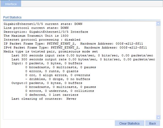
Displaying the general information and statistics of an interface
Configuring MAC addresses
MAC address configurations related to interfaces apply only to Layer 2 Ethernet interfaces.
This chapter provides information about the management of static and dynamic MAC address entries. It does not provide information about multicast MAC address entries.
Overview
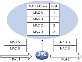
A device maintains a MAC address table for frame forwarding. Each entry in this table indicates the MAC address of a connected device, to which interface this device is connected and to which VLAN the interface belongs. A MAC address table consists of two types of entries: static and dynamic. Static entries are manually configured and never age out. Dynamic entries can be manually configured or dynamically learned and will age out.
When a frame arrives at a port, Port A for example, the device performs the following tasks:
1. Checks the frame for the source MAC address (MAC-SOURCE for example).
2. Looks up the MAC address in the MAC address table.
¡ If an entry is found, updates the entry.
¡ If no entry is found, adds an entry for the MAC address and the receiving port (Port A) to the MAC address table.
When receiving a frame destined for MAC-SOURCE, the device looks up the MAC address in the MAC address table and forwards the frame from port A.
|
|
NOTE: Dynamically learned MAC addresses cannot overwrite static MAC address entries, but the static MAC address entries can overwrite dynamically learned MAC addresses. |
When forwarding a frame, the device uses the following forwarding modes based on the MAC address table:
· Unicast mode—If an entry matching the destination MAC address exists, the device forwards the frame directly from the sending port recorded in the entry.
· Broadcast mode—If the device receives a frame with a destination address of all Fs, or no entry matches the destination MAC address, the device broadcasts the frame to all the ports except the receiving port.
Figure 1 MAC address table of the device
Configuring a MAC address entry
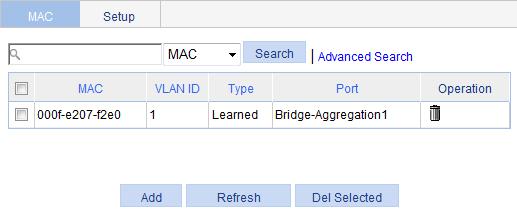
1. From the navigation tree, select Network > MAC.
The system automatically displays the MAC tab, which shows all the MAC address entries on the device.
2. Click Add.
The page for creating MAC address entries appears.
Figure 3 Creating a MAC address entry
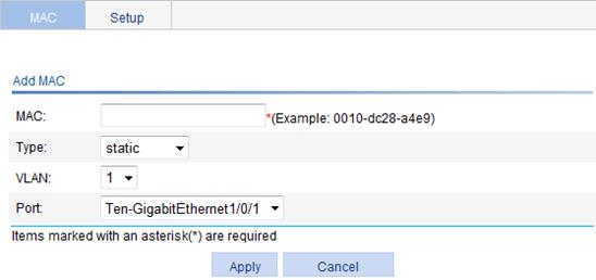
3. Configure the MAC address entry, as described in Table 1.
4. Click Apply.
|
Item |
Description |
|
MAC |
Set the MAC address to be added. |
|
Type |
Set the type of the MAC address entry: · static—Static MAC address entries that never age out. · dynamic—Dynamic MAC address entries that will age out. · blackhole—Blackhole MAC address entries that never age out. The tab displays the following types of MAC address entries: · Config static—Static MAC address entries manually configured by the users. · Config dynamic—Dynamic MAC address entries manually configured by the users. · Blackhole—Blackhole MAC address entries. · Learned—Dynamic MAC address entries learned by the device. · Other—Other types of MAC address entries. |
|
VLAN ID |
Set the ID of the VLAN to which the MAC address belongs. |
|
Port |
Set the port to which the MAC address belongs. |
Setting the aging time of MAC address entries
1. From the navigation tree, select Network > MAC.
2. Click the Setup tab.
The page for setting the MAC address entry aging time appears.
Figure 4 Setting the aging time for MAC address entries
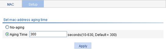
3. Set the aging time, as described in Table 2.
4. Click Apply.
|
Item |
Description |
|
No-aging |
Specify that the MAC address entry never ages out. |
|
Aging Time |
Set the aging time for the MAC address entry. |
MAC address configuration example
Network requirements
Use the MAC address table management function of the Web-based NMS. Create a static MAC address 00e0-fc35-dc71 for Ten-GigabitEthernet 1/0/1 in VLAN 1.
Configuration procedure
To create a static MAC address entry:
1. From the navigation tree, select Network > MAC to enter the MAC tab.
2. Click Add.
The page shown in Figure 5 appears.
3. Enter MAC address 00e0-fc35-dc71, select static from the Type list, select 1 from the VLAN list, and select Ten-GigabitEthernet1/0/1 from the Port list.
4. Click Apply.
Figure 5 Creating a static MAC address entry

Configuring VLANs
Overview
Ethernet is a network technology based on the Carrier Sense Multiple Access/Collision Detect (CSMA/CD) mechanism. The medium is shared, so collisions and excessive broadcasts are common on an Ethernet. To address this issue, virtual LAN (VLAN) was introduced to break a LAN down into separate VLANs. VLANs are isolated from each other at Layer 2. A VLAN is a bridging domain, and all broadcast traffic is contained within it, as shown in Figure 6.
You can implement VLANs based on a variety of criteria. However, the Web interface is available only for port-based VLANs, which group VLAN members by port. A port forwards traffic for a VLAN only after it is assigned to the VLAN.
For more information about VLAN, see "About the H3C Access Controllers Web-Based Configuration Guide."
Configuration guidelines
When you configure VLAN, follow these guidelines:
· VLAN 1 is the default VLAN, which cannot be manually created or removed.
· Some VLANs are reserved for special purposes. You cannot manually create or remove them.
· Dynamic VLANs cannot be manually removed.
· By default, an access port is not a tagged member of a VLAN, and a hybrid or trunk port is a tagged member of VLAN 2 to VLAN 4049.
Recommended configuration procedure
|
Step |
Remarks |
|
Required. |
|
|
Required. Select either task. Configure the untagged member ports and tagged member ports of the VLAN, or remove ports from the VLAN. |
|
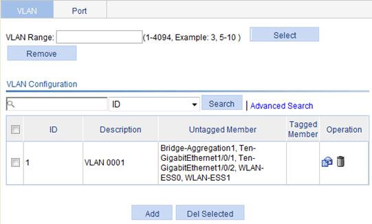
Creating a VLAN
1. From the navigation tree, select Network > VLAN.
The system automatically selects the VLAN tab and enters the page, as shown in Figure 7.
Figure 7 VLAN configuration page
|
|
TIP: To easily configure a specific range of VLANs, enter a VLAN range in the VLAN Range field and click Select, and all undesired VLANs will be filtered out. If you click Remove, all VLANs within this range will be deleted. |
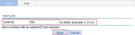
2. Click Add to enter the page for creating a VLAN.
3. On the page that appears, enter the ID of the VLAN you want to create.
4. Click Apply.

Modifying a VLAN
1. From the navigation tree, select Network > VLAN.
The system automatically selects the VLAN tab and enters the page, as shown in Figure 7.
2. Click the ![]() icon of the VLAN you want to modify to enter the page, as shown in Figure 9.
icon of the VLAN you want to modify to enter the page, as shown in Figure 9.
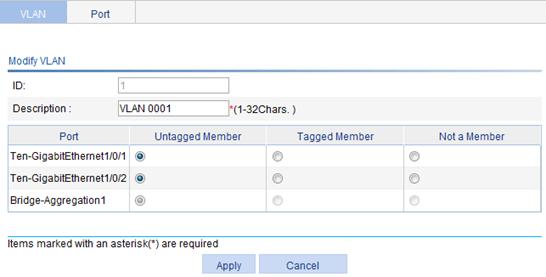
3. Configure the description and port members for the VLAN, as described in Table 3.
4. Click Apply.
|
Item |
Description |
|
|
ID |
Display the ID of the VLAN to be modified. |
|
|
Description |
Set the description string of the VLAN. By default, the description string of a VLAN is its VLAN ID, such as VLAN 0001. |
|
|
Port |
Untagged Member |
Find the port to be modified and select the Untagged Member, Tagged Member, or Not a Member option for the port: · Untagged—Indicates that the port sends the traffic of the VLAN with the VLAN tag removed. · Tagged—Indicates that the port sends the traffic of the VLAN without removing the VLAN tag. · Not a Member—Removes the port from the VLAN.
When you configure an access port as a tagged member of a VLAN, the link type of the port is automatically changed into hybrid. |
|
Tagged Member |
||
|
Not a Member |
||
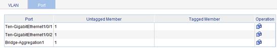
Modifying a port
1. From the navigation tree, select Network > VLAN.
2. Click the Port tab.
Figure 10 Port configuration page
3. Click the ![]() icon for the port to be modified.
icon for the port to be modified.

4. Configure the port, as described in Table 4.
5. Click Apply.
|
Item |
Description |
|
|
Port |
Display the port to be modified. |
|
|
Untagged Member |
Display the VLAN(s) to which the port belongs as an untagged member. |
|
|
Tagged Member |
Display the VLAN(s) to which the port belongs as a tagged member. |
|
|
Member Type |
Untagged |
Select the Untagged, Tagged, or Not a Member option: · Untagged—Indicates that the port sends the traffic of the VLAN with the VLAN tag removed. · Tagged—Indicates that the port sends the traffic of the VLAN without removing the VLAN tag. · Not a Member—Removes the port from the VLAN.
· You cannot configure an access port as an untagged member of a nonexistent VLAN. · When you configure an access port as a tagged member of a VLAN, or configure a trunk port as an untagged member of multiple VLANs in bulk, the link type of the port is automatically changed into hybrid. · You can configure a hybrid port as a tagged or untagged member of a VLAN only if the VLAN is an existing, static VLAN. |
|
Tagged |
||
|
Not a Member |
||
|
VLAN ID |
Specify the VLAN to which the port belongs. |
|
VLAN configuration example
Network requirements
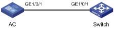
As shown in Figure 12:
· GigabitEthernet 1/0/1 of the AC is connected to GigabitEthernet 1/0/1 of Switch.
· GigabitEthernet 1/0/1 on both devices are hybrid ports with VLAN 100 as the default VLAN.
Configure GigabitEthernet 1/0/1 to permit packets of VLAN 2, VLAN 6 through VLAN 50, and VLAN 100 to pass through.
Configuring the AC
1. Create VLAN 2, VLAN 6 through VLAN 50, and VLAN 100:
a. Select Network > VLAN from the navigation tree to enter the VLAN tab.
b. Click Add.
c. Enter VLAN IDs 2,6-50,100.
d. Click Apply.

2. Configure GigabitEthernet 1/0/1 as an untagged member of VLAN 100:
a. Enter 100 in the VLAN Range field.
b. Click Select to display only the information of VLAN 100.

c. Click the ![]() icon for VLAN 100.
icon for VLAN 100.
The page for modifying the VLAN appears.
d. Select the Untagged Member option for port GigabitEthernet 1/0/1.
e. Click Apply.
3. Configure GigabitEthernet 1/0/1 as a tagged member of VLAN 2, and VLAN 6 through VLAN 50:
a. Select Network > VLAN from the navigation tree and then select the Port tab.
b. Click the ![]() icon for
GigabitEthernet 1/0/1.
icon for
GigabitEthernet 1/0/1.
The page for modifying the port appears.
c. Select the Tagged option, and enter VLAN IDs 2, 6-50.

d. Click Apply.
A dialog box appears asking you to confirm the operation.
e. Click OK.
Configuring the switch
The configuration on Switch is similar to the configuration on the AC.
Configuring ARP
Overview
Introduction to ARP
The Address Resolution Protocol (ARP) is used to resolve an IP address into an Ethernet MAC address (or physical address).
In an Ethernet LAN, a device uses ARP to resolve the IP address of the next hop to the corresponding MAC address.
For more information about ARP, see "About the H3C Access Controllers Web-Based Configuration Guide."
Introduction to gratuitous ARP
Gratuitous ARP packets
In a gratuitous ARP packet, the sender IP address and the target IP address are the IP address of the sending device, the sender MAC address is the MAC address of the sending device, and the target MAC address is the broadcast address ff:ff:ff:ff:ff:ff.
A device sends a gratuitous ARP packet to perform the following tasks:
· Determines whether its IP address is already used by another device. If the IP address is already used, the device will be informed of the conflict by an ARP reply.
· Informs other devices of the change of its MAC address, if any.
Learning of gratuitous ARP packets
With this feature enabled, a device, upon receiving a gratuitous ARP packet, adds an ARP entry that contains the sender IP and MAC addresses in the packet to its ARP table. If the corresponding ARP entry exists, the device updates the ARP entry.
With this feature disabled, the device uses the received gratuitous ARP packets to update existing ARP entries, but not to create new ARP entries.
Displaying ARP entries
From the navigation tree, select Network > ARP Management. The default ARP Table page appears, as shown in Figure 17. All ARP entries are displayed on the page.
Figure 17 Displaying ARP entries

Creating a static ARP entry
1. From the navigation tree, select Network > ARP Management.
The default ARP Table page appears, as shown in Figure 17.
2. Click Add .
The New Static ARP Entry page appears.
Figure 18 Adding a static ARP entry

3. Configure the static ARP entry, as described in Table 5.
4. Click Apply.
|
Item |
Description |
|
|
IP Address |
Enter an IP address for the static ARP entry. |
|
|
MAC Address |
Enter a MAC address for the static ARP entry. |
|
|
Advanced Options |
VLAN ID |
Enter a VLAN ID and specify a port for the static ARP entry. The VLAN ID must be the ID of the VLAN that has already been created, and the port must belong to the VLAN. The corresponding VLAN interface must have been created. |
|
Port |
||
Removing ARP entries
1. From the navigation tree, select Network > ARP Management.
The default ARP Table page appears, as shown in Figure 17.
2. Remove ARP entries:
¡ To remove specific ARP entries, select target ARP entries, and click Del Selected.
¡ To remove all static and dynamic ARP entries, click Delete Static and Dynamic.
¡ To remove all static ARP entries, click Delete Static.
¡ To remove all dynamic ARP entries, click Delete Dynamic.
Configuring gratuitous ARP
1. From the navigation tree, select Network > ARP Management.
2. Click the Gratuitous ARP tab.
Figure 19 Configuring gratuitous ARP

3. Configure gratuitous ARP, as described in Table 6.
4. Click Apply.
|
Item |
Description |
|
Disable gratuitous ARP packets learning function |
Disable learning of ARP entries according to gratuitous ARP packets. Enabled by default. |
|
Send gratuitous ARP packets when receiving ARP requests from another network segment |
Enable the device to send gratuitous ARP packets when it receives ARP requests from another network segment. Disabled by default. |
Static ARP configuration example
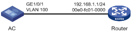
Network requirements
To enhance communication security between the AC and the router, configure a static ARP entry on the AC.
Configuration procedure
1. Create VLAN 100:
a. Select Network > VLAN from the navigation tree to enter the default VLAN page.
b. Click Add.
c. Enter 100 for VLAN ID.
d. Click Apply.
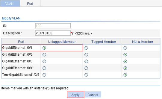
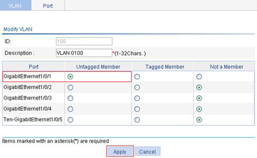
2. Add GigabitEthernet 1/0/1 to VLAN 100:
a. On the VLAN
page, click the ![]() icon
of VLAN 100.
icon
of VLAN 100.
b. Select the Untagged Member option for GigabitEthernet1/0/1.
c. Click Apply.
Figure 22 Adding GigabitEthernet 1/0/1 to VLAN 100
3. Configure VLAN-interface 100 and its IP address:
a. Select Device > Interface from the navigation tree.
b. Click Add.
c. On the page that appears, select Vlan-interface from the Interface Name list, and enter 100, select the Static Address option for IP Config, enter 192.168.1.2 for IP Address., and select 24 (255.255.255.0) for Mask.
d. Click Apply.
Figure 23 Configuring VLAN-interface 100

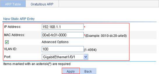
4. Create a static ARP entry:
a. Select Network > ARP Management from the navigation tree to enter the default ARP Table page.
b. Click Add.
c. On the page that appears, enter 192.168.1.1 for IP Address, enter 00e0-fc01-0000 for MAC Address, select the Advanced Options option, enter 100 for VLAN ID, and select GigabitEthernet1/0/1 from the Port list.
d. Click Apply.
Figure 24 Creating a static ARP entry
Configuring ARP attack protection
Overview
Although ARP is easy to implement, it does not provide any security mechanism and is prone to network attacks and viruses, which threaten LAN security. This chapter describes features that a device can use to detect and prevent attacks.
ARP detection
The ARP detection feature enables access devices to block ARP packets from unauthorized clients to prevent user spoofing and gateway spoofing attacks.
ARP detection provides the following functions:
· User validity check—The device compares the sender IP and MAC addresses of a received ARP packet against the static IP source guard binding entries, DHCP snooping entries, 802.1X security entries, or OUI MAC addresses. If no match is found, the ARP packet is discarded.
· ARP packet validity check—The device does not check ARP packets received from an ARP trusted port. Upon receiving an ARP packet from an ARP untrusted port, the device checks the ARP packet based on source MAC address, destination MAC address, or source and destination IP addresses. ARP packets that fail the check are discarded.
For more information about ARP detection, see "About the H3C Access Controllers Web-Based Configuration Guide."
Source MAC address based ARP attack detection
This feature allows the device to check the source MAC address of ARP packets delivered to the CPU. If the number of ARP packets from a MAC address exceeds the specified threshold within 5 seconds, the device considers this an attack and adds the MAC address to the attack detection table. Before the attack detection entry is aged out, the device generates a log message when it receives an ARP packet sourced from that MAC address and filters out subsequent ARP packets from that MAC address (in filter mode), or only generates a log message upon receiving an ARP packet sourced from that MAC address (in monitor mode).
A gateway or critical server might send a large number of ARP packets. To prevent these ARP packets from being discarded, you can specify the MAC address of the gateway or server as a protected MAC address. A protected MAC address is excluded from ARP attack detection even if it is an attacker.
ARP active acknowledgement
The ARP active acknowledgement feature is configured on gateway devices to identify invalid ARP packets.
ARP active acknowledgement works before the gateway creates or modifies an ARP entry to avoid generating any incorrect ARP entry. For more information about its working mechanism, see ARP Attack Protection Technology White Paper.
ARP packet source MAC address consistency check
This feature enables a gateway device to filter out ARP packets with the source MAC address in the Ethernet header different from the sender MAC address in the ARP message, so that the gateway device can learn correct ARP entries.
Configuring ARP detection
|
|
IMPORTANT: To check user validity, you must configure DHCP snooping entries, or 802.1X security entries. Otherwise, all ARP packets received from an ARP untrusted port are discarded. |
1. From the navigation tree, select Network > ARP Anti-Attack.
The default ARP Detection page appears, as shown in Figure 25.
Figure 25 ARP Detection configuration page

2. Configure ARP detection, as described in Table 7.
3. Click Apply.
|
Item |
Description |
|
VLAN Settings |
Select VLANs on which ARP detection is to be enabled. To add VLANs to the Enabled VLANs list box, select one or multiple VLANs from the Disabled VLANs list box and click the << button. To remove VLANs from the Enabled VLANs list box, select one or multiple VLANs from the list box and click the >> button. |
|
Trusted Ports |
Select trusted ports and untrusted ports. To add ports to the Trusted Ports list box, select one or multiple ports from the Untrusted Ports list box and click the << button. To remove ports from the Trusted Ports list box, select one or multiple ports from the list box and click the >> button. |
|
ARP Packet Validity Check |
Select the ARP packet validity check mode: · Discard the ARP packet whose sender MAC address is different from the source MAC address in the Ethernet header. · Discard the ARP packet whose target MAC address is all 0s, all 1s, or inconsistent with the destination MAC address in the Ethernet header. · Discard the ARP request whose source IP address is all 0s, all 1s, or a multicast address, and discard the ARP reply whose source and destination IP addresses are all 0s, all 1s, or multicast addresses. ARP packet validity check takes precedence over user validity check. If none of the ARP packet validity check modes are selected, the system does not check the validity of ARP packets |
Configuring other ARP attack protection functions
Other ARP attack protection functions include source MAC address-based ARP attack detection, ARP active acknowledgement, and ARP packet source address consistency check.
1. From the navigation tree, select Network > ARP Anti-Attack.
2. Click the Advanced Configuration tab.
Figure 26 Advanced Configuration page
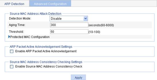
3. Configure ARP attack protection parameters, as described in Table 8.
4. Click Apply.
|
Item |
Description |
|
|
Source MAC Address Attack Detection |
Detection Mode |
Select the detection mode for source MAC address based ARP attack detection: · Disable—The source MAC address attack detection is disabled. · Filter Mode—The device generates an alarm and filters out ARP packets sourced from a MAC address if the number of ARP packets received from the MAC address within five seconds exceeds the specified value. · Monitor Mode—The device only generates an alarm if the number of ARP packets sent from a MAC address within five seconds exceeds the specified value. |
|
Aging Time |
Enter the aging time of the source MAC address based ARP attack detection entries. |
|
|
Threshold |
Enter the threshold of source MAC address based ARP attack detection. |
|
|
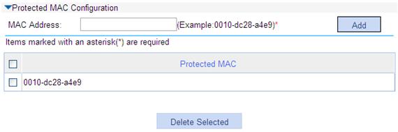
Protected MAC Configuration |
To add a protected MAC address: 1. Expand Protected MAC Configuration to display information, as shown in Figure 27. 2. Enter a MAC address. 3. Click Add to add a protected MAC address. A protected MAC address is excluded from ARP attack detection even if it is an attacker. You can specify certain MAC addresses as a protected MAC address, for example, a gateway or a specific server. |
|
|
Enable ARP Packet Active Acknowledgement |
Enable or disable ARP packet active acknowledgement. |
|
|
Enable Source MAC Address Consistency Check |
Enable or disable source MAC address consistency check. |
|
Figure 27 Protected MAC configuration
Configuring IGMP snooping
Overview
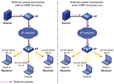
IGMP snooping runs on a Layer 2 switch as a multicast constraining mechanism to improve multicast forwarding efficiency. It creates Layer 2 multicast forwarding entries from IGMP packets that are exchanged between the hosts and the router.
As shown in Figure 28, when IGMP snooping is not enabled, the Layer 2 switch floods multicast packets to all hosts. When IGMP snooping is enabled, the Layer 2 switch forwards multicast packets of known multicast groups to only the receivers.
Figure 28 Multicast forwarding before and after IGMP snooping runs
For more information about IGMP snooping, see "About the H3C Access Controllers Web-Based Configuration Guide."
Recommended configuration procedure
|
Step |
Remarks |
|
Required. By default, IGMP snooping is disabled. |
|
|
Required. Enable IGMP snooping in the VLAN and configure the IGMP snooping version and querier feature. By default, IGMP snooping is disabled in a VLAN.
· IGMP snooping must be enabled globally before it can be enabled in a VLAN. · After enabling IGMP snooping in a VLAN, do not enable IGMP or PIM on the corresponding VLAN interface, and vice versa. · When you enable IGMP snooping in a VLAN, this function takes effect for ports in this VLAN only. |
|
|
Optional. Configure the maximum number of multicast groups allowed and the fast leave function for ports in the specified VLAN.
· Multicast routing or IGMP snooping must be enabled globally before IGMP snooping can be enabled on a port. · IGMP snooping configured on a port takes effect only after IGMP snooping is enabled in the VLAN or IGMP is enabled on the VLAN interface. |
|
|
Optional. |
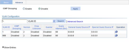
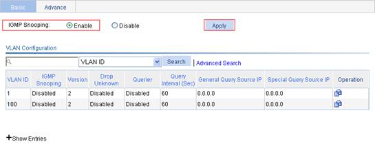
Enabling IGMP snooping globally
1. From the navigation tree, select Network > IGMP snooping.
The basic configuration page appears, as shown in Figure 29.
2. Select Enable, and click Apply.
Figure 29 Basic IGMP snooping configurations
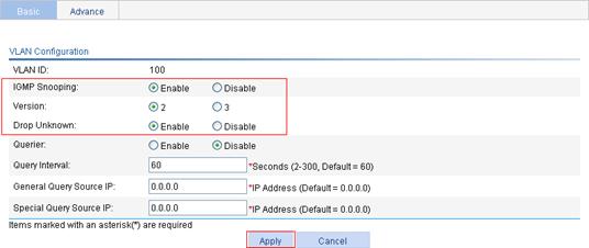
Configuring IGMP snooping on a VLAN
1. From the navigation tree Select Network > IGMP snooping.
The basic configuration page appears, as shown in Figure 29.
2. Click the ![]() icon corresponding to the VLAN to enter the page where you can configure IGMP snooping in the
VLAN, as shown in Figure 30.
icon corresponding to the VLAN to enter the page where you can configure IGMP snooping in the
VLAN, as shown in Figure 30.
Figure 30 Configuring IGMP snooping in the VLAN

3. Configure IGMP snooping, as described in Table 9.
4. Click Apply.
|
Item |
Description |
|
VLAN ID |
This field displays the ID of the VLAN to be configured. |
|
IGMP snooping |
Enable or disable IGMP snooping in the VLAN. You can proceed with the subsequent configurations only if Enable is selected. |
|
Version |
By configuring an IGMP snooping version, you configure the versions of IGMP messages that IGMP snooping can process. · IGMP snooping version 2 can process IGMPv1 and IGMPv2 messages, but not IGMPv3 messages, which will be flooded in the VLAN. · IGMP snooping version 3 can process IGMPv1, IGMPv2, and IGMPv3 messages.
If you change IGMPv3 snooping to IGMPv2 snooping, the system clears all IGMP snooping forwarding entries that are dynamically added. |
|
Drop Unknown |
Enable or disable the function of dropping unknown multicast packets. Unknown multicast data refers to multicast data for which no entries exist in the IGMP snooping forwarding table. · With the function of dropping unknown multicast data enabled, the device drops all the received unknown multicast data. · With the function of dropping unknown multicast data disabled, the device floods unknown multicast data in the VLAN to which the unknown multicast data belong. |
|
Querier |
Enable or disable the IGMP snooping querier function. On an IP multicast network that runs IGMP, a Layer 3 device acts as an IGMP querier to send IGMP queries and establish and maintain multicast forwarding entries for correct multicast traffic forwarding at the network layer. On a network without Layer 3 multicast devices, no IGMP querier-related function can be implemented because a Layer 2 device does not support IGMP. To implement IGMP querier-related function, you can enable IGMP snooping querier on a Layer 2 device so that the device can generate and maintain multicast forwarding entries at data link layer. |
|
Query interval |
Configure the IGMP query interval. |
|
General Query Source IP |
Source IP address of IGMP general queries. |
|
Special Query Source IP |
Source IP address of IGMP group-specific queries. |
Configuring IGMP snooping on a port
1. From the navigation tree, select Network > IGMP snooping.
The basic configuration page appears, as shown in Figure 29.
2. Click the Advance tab.
Figure 31 Advanced configuration

3. Configure IGMP snooping on a port, as described in Table 10.
4. Click Apply.
|
Item |
Description |
|
Port |
Select the port on which advanced IGMP snooping features are to be configured. After a port is selected, advanced features configured on this port are displayed at the lower part of the page. |
|
VLAN ID |
Specify a VLAN in which you can configure the fast leave function for the port or the maximum number of multicast groups allowed on the port. |
|
Group Limit |
Configure the maximum number of multicast groups that the port can join. With this feature, you can regulate multicast traffic on the port.
When the number of multicast groups a port has joined reaches the configured threshold, the system deletes all the forwarding entries persistent on that port from the IGMP snooping forwarding table, and the hosts on the port must join the multicast groups again. |
|
Fast Leave |
Enable or disable the fast leave function for the port. With the fast-leave function enabled on a port, the device, when receiving an IGMP leave message on the port, immediately deletes that port from the outgoing port list of the corresponding forwarding entry. Then, when receiving IGMP group-specific queries for that multicast group, the device will not forward them to that port. You can enable IGMP snooping fast-leave processing on a port that has only one receiver host attached to save bandwidth and resources. If a port has multiple hosts attached and the function of dropping unknown multicast packets has been enabled on the switch or in the VLAN where the port resides, you should not enable IGMP snooping fast-leave processing on this port. Otherwise, other hosts attached to this port in the same multicast group cannot receive the multicast data for the group. |
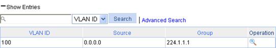
Displaying IGMP snooping multicast entry information
1. From the navigation tree, select Network > IGMP snooping.
The basic configuration page appears, as shown in Figure 29.
2. Click the plus sign (+) in front of Show Entries to display IGMP snooping multicast entries, as shown in Figure 32.
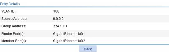
Figure 32 Displaying entry information
3. Click the ![]() icon corresponding
to an entry to display the detailed information of the entry, as shown in Figure 33.
icon corresponding
to an entry to display the detailed information of the entry, as shown in Figure 33.
Figure 33 Detailed information of an entry

|
Field |
Description |
|
VLAN ID |
ID of the VLAN to which the entry belongs. |
|
Source |
Multicast source address, where 0.0.0.0 indicates all multicast sources. |
|
Group |
Multicast group address. |
|
Router port |
All router ports. |
|
Member port |
All member ports. |
IGMP snooping configuration example
Network requirements
The multicast source sends multicast data to group 224.1.1.1. Host A is a receiver of the multicast group.
IGMPv2 runs on Router A and IGMPv2 snooping runs on AC. Router A acts as the IGMP querier.
Perform the configuration so Host A can receive the multicast data addressed to the multicast group 224.1.1.1, and AC drops unknown multicast data instead of flooding it in the VLAN.

Configuring Router A
Enable IP multicast routing, enable PIM-DM on each interface, and enable IGMP on Ethernet 1/1. (Details not shown.)
Configuring the AC
1. Create VLAN 100:
a. Select Network > VLAN from the navigation tree to enter the VLAN displaying page.
b. Click Add.
c. Enter the VLAN ID 100.
d. Click Apply.

2. Configure GigabitEthernet 1/0/1 and GigabitEthernet 1/0/2 as untagged members of VLAN 100:
a. Click the ![]() icon of VLAN 100 to enter its configuration page.
icon of VLAN 100 to enter its configuration page.
b. Select the Untagged Member option for GigabitEthernet 1/0/1 and GigabitEthernet 1/0/2, as shown in Figure 36.
c. Click Apply.
Figure 36 Adding a port to the VLAN

3. Enable IGMP snooping globally:
a. Select Network > IGMP snooping from the navigation tree to enter the basic configuration page.
b. Select the Enable option for IGMP Snooping.
c. Click Apply.
Figure 37 Enabling IGMP snooping globally
4. Enable IGMP snooping and the function for dropping unknown multicast data on VLAN 100:
a. Click the ![]() icon
corresponding to VLAN 100.
icon
corresponding to VLAN 100.
b. On the page that appears, select the Enable option for IGMP Snooping, select the 2 option for Version, and select the Enable option for Drop Unknown.
c. Click Apply.
Figure 38 Configuring the VLAN
Verifying the configuration
Display the IGMP snooping multicast entry information on AC.
1. From the navigation tree, select Network > IGMP snooping.
The basic configuration page appears.
2. Click the plus sign (+) in front of Show Entries to view IGMP snooping multicast entries, as shown in Figure 39.
Figure 39 IGMP snooping multicast entry information displaying page

3. Click the ![]() icon corresponding
to the multicast entry to view information about this entry, as shown in Figure 40. The page shows that
GigabitEthernet 1/0/2 of AC is added
to multicast group 224.1.1.1.
icon corresponding
to the multicast entry to view information about this entry, as shown in Figure 40. The page shows that
GigabitEthernet 1/0/2 of AC is added
to multicast group 224.1.1.1.
Figure 40 Information about an IGMP snooping multicast entry
Configuring IPv4 and IPv6 routing
The term router in this document refers to routers, access controllers, unified switches, and access controller modules.
Overview
Upon receiving a packet, a router determines the optimal route based on the destination address and forwards the packet to the next router in the path. When the packet reaches the last router, it forwards the packet to the destination host. Routing provides the path information that guides the forwarding of packets.
A router selects optimal routes from the routing table, and sends them to the forwarding information base (FIB) table to guide packet forwarding. Each router maintains a routing table and a FIB table.
Static routes are manually configured. If a network's topology is simple, you only need to configure static routes for the network to work correctly. Static routes cannot adapt to network topology changes. If a fault or a topological change occurs in the network, the network administrator must modify the static routes manually.
For more information about routing table and static routing, see "About the H3C Access Controllers Web-Based Configuration Guide."
Configuration guidelines
When you configure a static route, follow these guidelines:
1. If you do not specify the preference when you configure a static route, the default preference is used. Reconfiguration of the default preference applies only to newly created static routes. The Web interface does not support configuration of the default preference.
2. When you configure a static route, the static route does not take effect if you specify the next hop address first and then configure it as the IP address of a local interface, such as an Ethernet interface and VLAN interface.
3. When specifying the output interface, note that the following guidelines:
¡ If NULL 0 or a loopback interface is specified as the output interface, you do not need to configure the next hop address.
¡ If a point-to-point interface is specified as the output interface, you do not need to specify the next hop or change the configuration after the peer address has changed. For example, a PPP interface obtains the peer's IP address through PPP negotiation, and you only need to specify it as the output interface.
¡ If you want to specify a broadcast interface (such as an Ethernet interface, virtual template, or VLAN interface) as the output interface, which might have multiple next hops, you must specify the next hop at the same time.
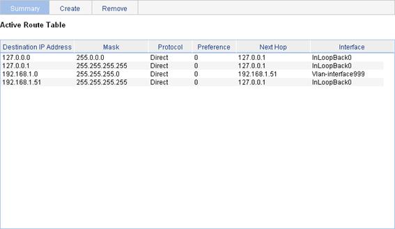
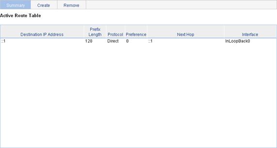
Displaying the IPv4 active route table
From the navigation tree, select Network > IPv4 Routing to enter the page, as shown in Figure 41.
Figure 41 IPv4 active route table
|
Field |
Description |
|
Destination IP Address |
Destination IP address and subnet mask of the IPv4 route. |
|
Mask |
|
|
Protocol |
Protocol that discovered the IPv4 route. |
|
Preference |
Preference value for the IPv4 route. The smaller the number, the higher the preference. |
|
Next Hop |
Next hop IP address of the IPv4 route. |
|
Interface |
Outgoing interface of the IPv4 route. Packets destined for the specified network segment will be sent out of the interface. |
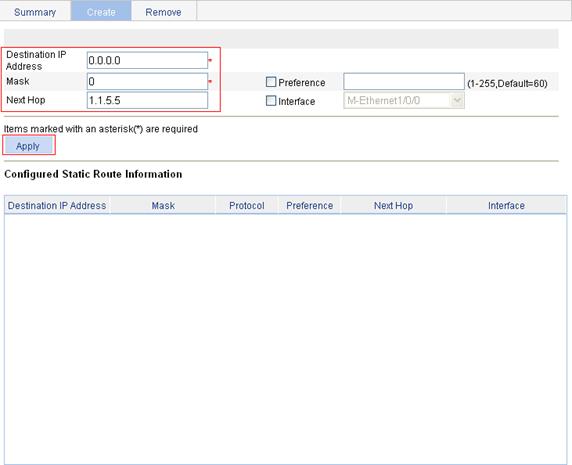
Creating an IPv4 static route
1. From the navigation tree, select Network > IPv4 Routing.
2. Click the Create tab.
Figure 42 Creating an IPv4 static route

3. Specify relevant information, as described in Table 13.
4. Click Apply.
|
Item |
Description |
|
Destination IP Address |
Enter the destination host or network IP address, in dotted decimal notation. |
|
Mask |
Enter the mask of the destination IP address. You can enter a mask length or a mask in dotted decimal notation. |
|
Preference |
Set a preference value for the static route. The smaller the number, the higher the preference. For example, specifying the same preference for multiple static routes to the same destination enables load sharing on the routes, while specifying different preferences enables route backup. |
|
Next Hop |
Enter the next hop IP address in dotted decimal notation. |
|
Interface |
Select the outgoing interface. You can select any available Layer 3 interface of the device, for example, a virtual interface. If you select NULL 0, the destination IP address is unreachable. If you select this option, leave the Next Hop field blank. Otherwise, your configuration does not take effect. |
Displaying the IPv6 active route table
From the navigation tree, select Network > IPv6 Routing to enter the page, as shown in Figure 43.
Figure 43 Displaying the IPv6 active route table
|
Field |
Description |
|
Destination IP Address |
Destination IP address and prefix length of the IPv6 route. |
|
Prefix Length |
|
|
Protocol |
Protocol that discovered the IPv6 route. |
|
Preference |
Preference value for the IPv6 route. The smaller the number, the higher the preference. |
|
Next Hop |
Next hop IP address of the IPv6 route. |
|
Interface |
Outgoing interface of the IPv6 route. Packets destined for the specified network segment will be sent out the interface. |
Creating an IPv6 static route
1. From the navigation tree, select Network > IPv6 Routing.
2. Click the Create tab.
Figure 44 Creating an IPv6 static route

3. Specify relevant information, as described in Table 15.
4. Click Apply.
|
Item |
Description |
|
Destination IP Address |
Enter the destination host or network IP address, in the X:X::X:X format. The 128-bit destination IPv6 address is a hexadecimal address with eight parts separated by colons (:). Each part is represented by a 4-digit hexadecimal integer. |
|
Prefix Length |
Enter the prefix length of the destination IPv6 address. |
|
Preference |
Set a preference value for the static route. The smaller the number, the higher the preference. For example, specifying the same preference for multiple static routes to the same destination enables load sharing on the routes, while specifying different priorities for them enables route backup. |
|
Next Hop |
Enter the next hop address, in the same format as the destination IP address. |
|
Interface |
Select the outgoing interface. You can select any available Layer 3 interface, for example, a virtual interface, of the device. If you select NULL 0, the destination IPv6 address is unreachable. |
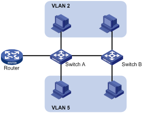
IPv4 and IPv6 static route configuration examples
IPv4 static route configuration example
Network requirements
The IP addresses of devices are shown in Figure 45. IPv4 static routes must be configured on Switch A, Switch B and AC for Host A and Host B to communicate with each other.

Configuration outlines
1. On Switch A, configure a default route with Switch B as the next hop.
2. On Switch B, configure one static route with Switch A as the next hop and the other with AC as the next hop.
3. On AC, configure a default route with Switch B as the next hop.
Configuration procedure
1. Configure a default route with the next hop address 1.1.4.2 on Switch A.
2. Configure two static routes on Switch B: one with destination address 1.1.2.0/24 and next hop address 1.1.4.1, and the other with destination address 1.1.3.0/24 and next hop address 1.1.5.6.
3. Configure a default route on AC:
a. Select Network > IPv4 Routing from the navigation tree.
b. Click the Create tab.
The IPv4 static route configuration page appears, as shown in Figure 46.
c. Enter 0.0.0.0 for Destination IP Address, 0 for Mask, and 1.1.5.5 for Next Hop.
d. Click Apply.
Figure 46 Configuring a default route
Verifying the configuration
1. Display the route table:
Enter the IPv4 route page of Switch A, Switch B, and AC, respectively, to verify that the newly configured static routes are displayed as active routes on the page.
2. Ping Host B from Host A (assuming both hosts run Windows XP):
C:\Documents and Settings\Administrator>ping 1.1.3.2
Pinging 1.1.3.2 with 32 bytes of data:
Reply from 1.1.3.2: bytes=32 time=1ms TTL=128
Reply from 1.1.3.2: bytes=32 time=1ms TTL=128
Reply from 1.1.3.2: bytes=32 time=1ms TTL=128
Reply from 1.1.3.2: bytes=32 time=1ms TTL=128
Ping statistics for 1.1.3.2:
Packets: Sent = 4, Received = 4, Lost = 0 (0% loss),
Approximate round trip times in milli-seconds:
Minimum = 1ms, Maximum = 1ms, Average = 1ms
IPv6 static route configuration example
Network requirements
The IP addresses of devices are shown in Figure 47. IPv6 static routes must be configured on Switch A, Switch B and AC for Host A and Host B to communicate with each other.

Configuration outlines
1. On Switch A, configure a default route with Switch B as the next hop.
2. On Switch B, configure one static route with Switch A as the next hop and the other with AC as the next hop.
3. On AC, configure a default route with Switch B as the next hop.
Configuration procedure
1. Configure a default route with the next hop address 4::2 on Switch A.
2. Configure two static routes on Switch B: one with destination address 1::/64 and next hop address 4::1, and the other with destination address 3::/64 and next hop address 5::1.
3. Configure a default route on AC:
a. Select Network > IPv6 Routing from the navigation tree.
b. Click the Create tab.
The IPv6 static route configuration page appears, as shown in Figure 48.
c. Enter :: for Destination IP Address, select 0 for Prefix Length, and enter 5::2 for Next Hop.
d. Click Apply.
Figure 48 Configuring a default route

Verifying the configuration
1. Display the route table:
Enter the IPv6 route page of Switch A, Switch B, and AC, respectively, to verify that the newly configured static routes are displayed as active routes on the page.
2. Ping Host B from Switch A:
<SwitchA> system-view
[SwitchA] ping ipv6 3::2
PING 3::2 : 56 data bytes, press CTRL_C to break
bytes=56 Sequence=1 hop limit=254 time = 63 ms
bytes=56 Sequence=2 hop limit=254 time = 62 ms
bytes=56 Sequence=3 hop limit=254 time = 62 ms
bytes=56 Sequence=4 hop limit=254 time = 63 ms
bytes=56 Sequence=5 hop limit=254 time = 63 ms
--- 3::2 ping statistics ---
5 packet(s) transmitted
5 packet(s) received
0.00% packet loss
round-trip min/avg/max = 62/62/63 ms
Configuring DHCP
DHCP overview
After the DHCP client is enabled on an interface, the interface can dynamically obtain an IP address and other configuration parameters from the DHCP server. This facilitates configuration and centralized management. For more information about the DHCP client configuration, see "Managing interfaces."
For more information about DHCP, see "About the H3C Access Controllers Web-Based Configuration Guide."
The Dynamic Host Configuration Protocol (DHCP) provides a framework to assign configuration information to network devices.
DHCP uses the client/server model. Figure 49 shows a typical a DHCP application.
Figure 49 A typical DHCP application
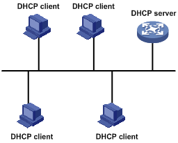
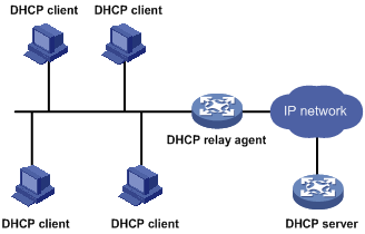
A DHCP client can obtain an IP address and other configuration parameters from a DHCP server on another subnet through a DHCP relay agent.
Figure 50 DHCP relay agent application
DHCP snooping overview
|
|
IMPORTANT: The DHCP snooping-enabled device must be between the DHCP client and relay agent, or between the DHCP client and server. It does not work if it is between the DHCP relay agent and DHCP server. |
As a DHCP security feature, DHCP snooping can implement the following functionality:
· Records IP-to-MAC mappings of DHCP clients.
· Ensures DHCP clients to obtain IP addresses from authorized DHCP servers.
Recording IP-to-MAC mappings of DHCP clients
DHCP snooping reads DHCP-REQUEST messages and DHCP-ACK messages from trusted ports to record DHCP snooping entries, including MAC addresses of clients, IP addresses obtained by the clients, ports that connect to DHCP clients, and VLANs to which the ports belong. ARP uses DHCP snooping entries to perform ARP detection (user validity check).
For more information about ARP detection, see "Configuring ARP attack protection."
Enabling DHCP clients to obtain IP addresses from authorized DHCP servers
If there is an unauthorized DHCP server on a network, DHCP clients might obtain invalid IP addresses and network configuration parameters, and cannot correctly communicate with other network devices. With DHCP snooping, the ports of a device can be configured as trusted or untrusted, ensuring the clients to obtain IP addresses from authorized DHCP servers.
· Trusted—A trusted port forwards DHCP messages correctly.
· Untrusted—An untrusted port discards the DHCP-ACK or DHCP-OFFER messages received from any DHCP server.
Configure ports connected to a DHCP server or another DHCP snooping device as trusted ports and configure other ports as untrusted ports.
Recommended configuration procedure (for DHCP server)
|
Step |
Remarks |
|
Required. Enable DHCP globally. By default, global DHCP is disabled. |
|
|
2. Creating an address pool for the DHCP server |
Required. Use at least one method.
· If the DHCP server and DHCP clients are on the same subnet, make sure the address pool is on the same network segment as the interface with the DHCP server enabled. Otherwise, the clients will fail to obtain IP addresses. · If a DHCP client obtains an IP address via a DHCP relay agent, an IP address pool on the same network segment as the DHCP relay agent interface must be configured. Otherwise, the client will fail to obtain an IP address. |
|
Optional. When receiving a client's request on an interface with the DHCP server enabled, the DHCP server will assign an IP address from its address pool to the DHCP client. With DHCP enabled, interfaces operate in DHCP server mode.
· An interface cannot serve as both the DHCP server and the DHCP relay agent. The most recent configuration takes effect. · The DHCP server works on interfaces with IP addresses manually configured only. |
|
|
Optional. |
Enabling DHCP
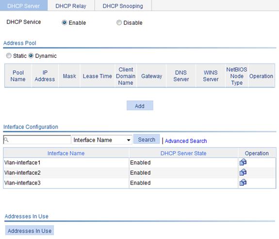
1. From the navigation tree, select Network > DHCP.
The default DHCP Server page appears, as shown in Figure 51.
2. On the upper part of the page, select the Enable option to enable DHCP globally.
Creating a static address pool for the DHCP server
1. From the navigation tree, select Network > DHCP.
The default DHCP Server page appears, as shown in Figure 51.
2. In the Address Pool area, select the Static option to view all static address pools.
3. Click Add.
Figure 52 Creating a static address pool

4. Configure the static address pool, as described in Table 16.
5. Click Apply.
|
Item |
Description |
|
IP Pool Name |
Enter the name of a static address pool. |
|
IP Address |
Enter an IP address and select a subnet mask for the static address pool. The IP address cannot be the IP address of any interface on the DHCP server. Otherwise, an IP address conflict might occur and the bound client cannot obtain an IP address correctly. You can enter a mask length or a mask in dotted decimal notation.. |
|
Mask |
|
|
Client MAC Address |
Configure the client MAC address or the client ID for the static address pool.
The client ID must be identical to the ID of the client to be bound. Otherwise, the client cannot obtain an IP address. |
|
Client ID |
|
|
Client Domain Name |
Enter the domain name suffix for the client. With the suffix assigned, the client only needs to enter part of a domain name, and the system adds the domain name suffix for name resolution. |
|
Gateway Address |
Enter the gateway addresses for the client. A DHCP client that wants to access an external host needs to send requests to a gateway. You can specify gateways in each address pool and the DHCP server will assign gateway addresses while assigning an IP address to the client. Up to eight gateways can be specified in a DHCP address pool, separated by commas. |
|
DNS Server Address |
Enter the DNS server addresses for the client. To allow the client to access a host on the Internet through DNS, you need to specify a DNS server address. Up to eight DNS servers can be specified in a DHCP address pool, separated by commas. |
|
WINS Server Address |
Enter the WINS server addresses for the client. If b-node is specified for the client, you do not need to specify any WINS server address. Up to eight WINS servers can be specified in a DHCP address pool, separated by commas. |
|
NetBIOS Node Type |
Select the NetBIOS node type for the client. |
Creating a dynamic address pool for the DHCP server
1. From the navigation tree, select Network > DHCP.
The default DHCP Server page appears, as shown in Figure 51.
2. In the Address Pool area, select the Dynamic option to view all dynamic address pools.
3. Click Add.
Figure 53 Creating a dynamic address pool

4. Configure the dynamic address pool, as described in Table 17.
5. Click Apply.
|
Item |
Description |
|
|
IP Pool Name |
Enter the name of a dynamic address pool. |
|
|
IP Address |
Enter an IP address segment for dynamic allocation. To avoid address conflicts, the DHCP server excludes the IP addresses used by gateways or FTP servers from dynamic allocation. You can enter a mask length or a mask in dotted decimal notation. |
|
|
Mask |
||
|
Lease Duration |
Unlimited |
Configure the address lease duration for the address pool. Unlimited indicates the infinite duration. |
|
days/hours/minutes/seconds |
||
|
Client Domain Name |
Enter the domain name suffix for the client. With the suffix assigned, the client only needs to enter part of a domain name, and the system will add the domain name suffix for name resolution. |
|
|
Gateway Address |
Enter the gateway addresses for the client. DHCP clients that want to access hosts outside the local subnet request gateways to forward data. You can specify gateways in each address pool for clients and the DHCP server will assign gateway addresses while assigning an IP address to the client. Up to eight gateways can be specified in a DHCP address pool, separated by commas. |
|
|
DNS Server Address |
Enter the DNS server addresses for the client. To allow the client to access a host on the Internet via the host name, you need to specify DNS server addresses. Up to eight DNS servers can be specified in a DHCP address pool, separated by commas. |
|
|
WINS Server Address |
Enter the WINS server addresses for the client. If b-node is specified for the client, you do not need to specify any WINS server address. Up to eight WINS servers can be specified in a DHCP address pool, separated by commas. |
|
|
NetBIOS Node Type |
Select the NetBIOS node type for the client. |
|
Enabling the DHCP server on an interface
1. From the navigation tree, select Network > DHCP.
The default DHCP Server page appears, as shown in Figure 51.
2. Click the ![]() icon next to a
specific interface to enter the page, as shown in Figure 54.
icon next to a
specific interface to enter the page, as shown in Figure 54.
3. Select the Enable option for DHCP Server.
4. Click Apply.
Figure 54 Configuring a DHCP server interface

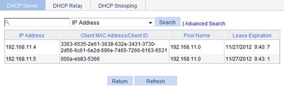
Displaying information about assigned IP addresses
1. From the navigation tree, select Network > DHCP > DHCP Server to enter the page, as shown in Figure 51.
2. In the Addresses In Use field on the lowest part of the page, click Addresses In Use to view information about the IP address assigned from the address pool.
Figure 55 Displaying addresses in use
|
Field |
Description |
|
IP Address |
Assigned IP address. |
|
Client MAC Address/Client ID |
Client MAC address or client ID bound to the IP address. |
|
Pool Name |
Name of the DHCP address pool where the IP address belongs. |
|
Lease Expiration |
Lease time of the IP address. |
Recommended configuration procedure (for DHCP relay agent)
|
Step |
Remarks |
|
1. Enabling DHCP and configuring advanced parameters for the DHCP relay agent |
Required. Enable DHCP globally and configure advanced DHCP parameters. By default, global DHCP is disabled. |
|
Required. To improve reliability, you can specify several DHCP servers as a group on the DHCP relay agent and correlate a relay agent interface with the server group. When the interface receives requesting messages from clients, the relay agent will forward them to all the DHCP servers of the group. |
|
|
Required. Enable the DHCP relay agent on an interface, and correlate the interface with a DHCP server group. With DHCP enabled, interfaces work in the DHCP server mode by default.
· An interface cannot serve as both the DHCP server and the DHCP relay agent. The most recent configuration takes effect. · If the DHCP relay agent is enabled on an Ethernet subinterface, a packet received from a client on this interface must contain a VLAN tag and the VLAN tag must be the same as the VLAN ID of the subinterface. Otherwise, the packet is discarded. · The DHCP relay agent works on interfaces with only IP addresses manually configured. · If an Ethernet subinterface serves as a DHCP relay agent, it conveys IP addresses only to subinterfaces of DHCP clients. In this case, a PC cannot obtain an IP address as a DHCP client. |
|
|
Optional. Create a static IP-to-MAC binding, and view static and dynamic bindings. The DHCP relay agent can dynamically record clients' IP-to-MAC bindings after clients get IP addresses. It also supports static bindings. You can manually configure IP-to-MAC bindings on the DHCP relay agent so that users can access external network using fixed IP addresses. By default, no static binding is created. |
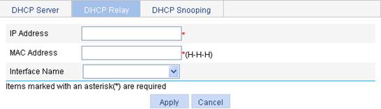
Enabling DHCP and configuring advanced parameters for the DHCP relay agent
1. From the navigation tree, select Network > DHCP.
2. Click the DHCP Relay tab.
Figure 56 DHCP relay agent configuration page

3. Select the Enable option for DHCP Service.
4. Click Display Advanced Configuration to expand the advanced DHCP relay agent configuration field, as shown in Figure 57.
Figure 57 Advanced DHCP relay agent configuration field
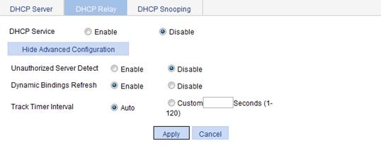
5. Configure the advanced DHCP relay agent parameters, as described in Table 19.
6. Click Apply. You must also click Apply for enabling the DHCP service.
|
Item |
Description |
|
Unauthorized Server Detect |
Enable or disable unauthorized DHCP server detection. There are unauthorized DHCP servers on networks, which reply to DHCP clients with incorrect IP addresses. When this feature is enabled, the DHCP relay agent will record the IP address of any DHCP server that assigned an IP address to the DHCP client and the receiving interface when it receives a DHCP request. The administrator can use this information to monitor and performs subsequent actions for DHCP unauthorized servers. The device creates a record once for each DHCP server for the administrator to determine unauthorized DHCP servers. After the information of recorded DHCP servers is cleared, the relay agent will record server information again. |
|
Dynamic Bindings Refresh |
Enable or disable periodic refresh of dynamic client entries, and set the refresh interval. Through the DHCP relay agent, a DHCP client sends a DHCP-RELEASE unicast message to the DHCP server to relinquish its IP address. The DHCP relay agent conveys the message to the DHCP server, but does not remove the IP address from dynamic client entries. To solve this problem, use the periodic refresh of dynamic client entries feature. When this feature is enabled, the DHCP relay agent uses the IP address of a client and the MAC address of the DHCP relay agent interface to periodically send a DHCP-REQUEST message to the DHCP server. · If the server returns a DHCP-ACK message or does not return any message within a specified interval, which means that the IP address is assignable, the DHCP relay agent will age out the client entry. · If the server returns a DHCP-NAK message, which means the IP address is still in use, the relay agent will not age it out. If the Auto option is selected, the refresh interval is calculated by the relay agent according to the number of client entries. |
|
Track Timer Interval |
Creating a DHCP server group
1. From the navigation tree, select Network > DHCP.
2. Click the DHCP Relay tab to enter the page, as shown in Figure 56.
3. In the Server Group field, click Add to enter the page, as shown in Figure 58.
Figure 58 Creating a server group

4. Specify the DHCP server group information, as described in Table 20.
5. Click Apply.
|
Item |
Description |
|
Server Group ID |
Enter the ID of a DHCP server group. You can create up to 20 DHCP server groups. |
|
IP Address |
Enter the IP address of a server in the DHCP server group. The server IP address cannot be on the same subnet as the IP address of the DHCP relay agent. Otherwise, the client cannot obtain an IP address. |
Enabling the DHCP relay agent on an interface
1. From the navigation tree, select Network > DHCP.
2. Click the DHCP Relay tab to enter the page, as shown in Figure 56.
3. In the Interface Config
field, click the ![]() icon of a specific
interface to enter the page, as
shown in Figure 59.
icon of a specific
interface to enter the page, as
shown in Figure 59.
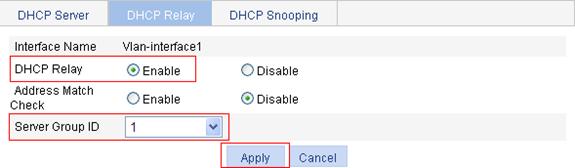
Figure 59 Configuring a DHCP relay agent interface
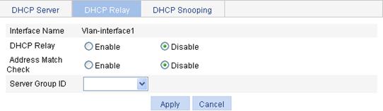
4. Configure the parameters, as described in Table 21.
5. Click Apply.
|
Item |
Description |
|
Interface Name |
This field displays the name of a specific interface. |
|
DHCP Relay |
Enable or disable the DHCP relay agent on the interface. If the DHCP relay agent is disabled, the DHCP server is enabled on the interface. |
|
Address Match Check |
Enable or disable IP address check. With this function enabled, the DHCP relay agent checks whether a requesting client's IP and MAC addresses match a binding (dynamic or static) on the DHCP relay agent. If not, the client cannot access outside networks via the DHCP relay agent. This prevents invalid IP address configuration. |
|
Server Group ID |
Correlate the interface with a DHCP server group. A DHCP server group can be correlated with multiple interfaces. |
Configuring and displaying clients' IP-to-MAC bindings
1. From the navigation tree, select Network > DHCP.
2. Click the DHCP Relay tab to enter the page, as shown in Figure 56.
3. In the User Information field, click User Information to view static and dynamic bindings.
Figure 60 Displaying clients' IP-to-MAC bindings

4. Click Add to enter the page, as shown in Figure 61.
Figure 61 Creating a static IP-to-MAC binding
5. Configure static IP-to-MAC binding, as described in Table 22.
6. Click Apply.
|
Item |
Description |
|
IP Address |
Enter the IP address of a DHCP client. |
|
MAC Address |
Enter the MAC address of the DHCP client. |
|
Interface Name |
Select the Layer 3 interface connected with the DHCP client.
The interface of a static binding entry must be configured as a DHCP relay agent. Otherwise, address entry conflicts might occur. |
Recommended configuration procedure (for DHCP snooping)
|
Step |
Remarks |
|
Required. By default, DHCP snooping is disabled. |
|
|
Required. Specify an interface as trusted and configure DHCP snooping to support Option 82. By default, an interface is untrusted and DHCP snooping does not support Option 82.
You need to specify the ports connected to the authorized DHCP servers as trusted to make sure DHCP clients can obtain valid IP addresses. The trusted port and the port connected to the DHCP client must be in the same VLAN. |
|
|
Optional. Display clients' IP-to-MAC bindings recorded by DHCP snooping. |
Enabling DHCP snooping
1. From the navigation tree, select Network > DHCP.
2. Click the DHCP Snooping tab.
3. Select the Enable option for DHCP Snooping.
Figure 62 Enabling DHCP snooping

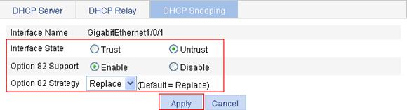
Configuring DHCP snooping functions on an interface
1. From the navigation tree, select Network > DHCP.
2. Click the DHCP Snooping tab to enter the page, as shown in Figure 62.
3. In the Interface Config field, click the ![]() icon of a specific interface.
icon of a specific interface.
Figure 63 Configuring DHCP snooping functions on an interface

4. Configure the parameters, as described in Table 23.
5. Click Apply.
|
Item |
Description |
|
Interface Name |
This field displays the name of a specific interface. |
|
Interface State |
Configure the interface as trusted or untrusted. |
|
Option 82 Support |
Configure DHCP snooping to support Option 82 or not. |
|
Option 82 Strategy |
Select the handling strategy for DHCP requests containing Option 82. The strategies include: · Drop—The message is discarded if it contains Option 82. · Keep—The message is forwarded without its Option 82 being changed. · Replace—The message is forwarded after its original Option 82 is replaced with the Option 82 padded in normal format. |
Displaying clients' IP-to-MAC bindings
1. From the navigation tree, select Network > DHCP.
2. Click the DHCP Snooping tab to enter the page, as shown in Figure 62.
3. Click User Information.
The DHCP snooping user information page appears, as shown in Figure 64.
Figure 64 DHCP snooping user information

4. View clients' IP-to-MAC bindings recorded by DHCP snooping, as described in Table 24.
|
Item |
Description |
|
IP Address |
This field displays the IP address assigned by the DHCP server to the client. |
|
MAC Address |
This field displays the MAC address of the client. |
|
Type |
This field displays the client type, which can be: · Dynamic—The IP-to-MAC binding is generated dynamically. · Static—The IP-to-MAC binding is configured manually. Static bindings are not supported. |
|
Interface Name |
This field displays the device interface to which the client is connected. |
|
VLAN |
This field displays the VLAN to which the device belongs. |
|
Remaining Lease Time |
This field displays the remaining lease time of the IP address. |
DHCP configuration examples
DHCP server configuration example
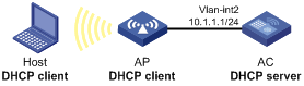
Network requirements
As shown in Figure 65, the DHCP client on subnet 10.1.1.0/24 obtains an IP address dynamically from the DHCP server (AC). The IP address of VLAN-interface 2 of the AC is 10.1.1.1/24.
In subnet 10.1.1.0/24, the address lease duration is ten days and twelve hours and the gateway address is 10.1.1.1.
Configuration procedure
1. Enable DHCP:
a. Select Network > DHCP from the navigation tree to enter the default DHCP Server page.
b. Select the Enable option for DHCP Service.
Figure 66 Enabling DHCP

2. Enable the DHCP server on VLAN-interface 2: (This operation can be omitted because the DHCP server is enabled on the interface by default.)
a. In the Interface Config
field, click the ![]() icon of VLAN-interface 2.
icon of VLAN-interface 2.
b. Select the Enable option for DHCP Server.
c. Click Apply.
Figure 67 Enabling the DHCP server on VLAN-interface 2

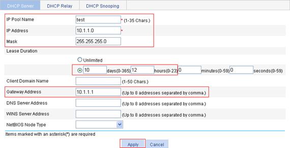
3. Configure a dynamic address pool for the DHCP server:
a. Select the Dynamic option in the Address Pool field (default setting), and click Add.
b. On the page that appears, enter test for IP Pool Name, enter 10.1.1.0 for IP Address, enter 255.255.255.0 for Mask, enter 10 days 12 hours 0 minutes 0 seconds for Lease Duration, and enter 10.1.1.1 for Gateway Address.
c. Click Apply.
Figure 68 Configuring a dynamic address pool for the DHCP server
DHCP relay agent configuration example
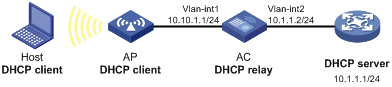
Network requirements
As shown in Figure 69, VLAN-interface 1 on the DHCP relay agent (AC) connects to the network where DHCP clients reside. The IP address of VLAN-interface 1 is 10.10.1.1/24 and the IP address of VLAN-interface 2 is 10.1.1.1/24. VLAN-interface 2 is connected to the DHCP server whose IP address is 10.1.1.1/24.
The AC forwards messages between DHCP clients and the DHCP server.
Configuration procedure
Because the DHCP relay agent and server are on different subnets, you must configure a static route or dynamic routing protocol so they can communicate.
1. Enable DHCP:
a. Select Network > DHCP from the navigation tree.
b. Click the DHCP Relay tab.
c. Select the Enable option for DHCP Service.
d. Click Apply.
Figure 70 Enabling DHCP

2. Configure a DHCP server group:
a. In the Server Group field, click Add.
b. Enter 1 for Server Group ID, and 10.1.1.1 for IP Address.
c. Click Apply.
Figure 71 Adding a DHCP server group

3. Enable the DHCP relay agent on VLAN-interface 1:
a. Click the ![]() icon
of VLAN-interface 1 in the Interface Config field.
icon
of VLAN-interface 1 in the Interface Config field.
b. Select the Enable option for DHCP Relay, and select 1 for Server Group ID.
c. Click Apply.
Figure 72 Enabling the DHCP relay agent on an interface and correlate it with a server group
DHCP snooping configuration example
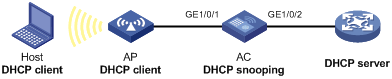
Network requirements
As shown in Figure 73, a DHCP snooping device (the AC) is connected to a DHCP server through GigabitEthernet 1/0/2, and to an AP through GigabitEthernet 1/0/1.
· Enable DHCP snooping on the AC and configure DHCP snooping to support Option 82. Configure the handling strategy for DHCP requests containing Option 82 as replace.
· Enable GigabitEthernet 1/0/2 to forward DHCP server responses. Disable GigabitEthernet 1/0/1 from forwarding DHCP server responses.
· Configure the AC to record clients' IP-to-MAC address bindings in DHCP-REQUEST messages and DHCP-ACK messages received from a trusted port.
Configuration procedure
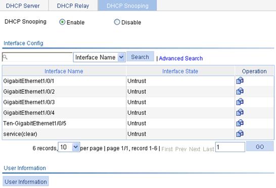
1. Enable DHCP snooping:
a. Select Network > DHCP from the navigation tree.
b. Click the DHCP Snooping tab.
c. Select the Enable option for DHCP Snooping.
Figure 74 Enabling DHCP snooping
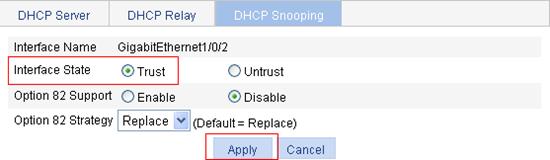
2. Configure DHCP snooping functions on GigabitEthernet 1/0/2:
a. Click the ![]() icon of
GigabitEthernet 1/0/2 on the interface list.
icon of
GigabitEthernet 1/0/2 on the interface list.
b. Select the Trust option for Interface State.
c. Click Apply.
Figure 75 Configuring DHCP snooping functions on GigabitEthernet 1/0/2
3. Configure DHCP snooping functions on GigabitEthernet 1/0/1:
a. Click the ![]() icon of GigabitEthernet 1/0/1 on the interface list.
icon of GigabitEthernet 1/0/1 on the interface list.
b. Select the Untrust option for Interface State.
c. Select the Enable option for Option 82 Support.
d. Select Replace for Option 82 Strategy.
e. Click Apply.
Figure 76 Configuring DHCP snooping functions on GigabitEthernet 1/0/1
Configuring link aggregation and LACP
Overview
Link aggregation aggregates multiple physical Ethernet ports into one logical link, also called an aggregation group.
It allows you to increase bandwidth by distributing traffic across the member ports in the aggregation group. In addition, it provides reliable connectivity because these member ports can dynamically back up each other.
Support for link aggregation depends on the device model. For more information, see "About the H3C Access Controllers Web-Based Configuration Guide."
Basic concepts of link aggregation
Aggregate interface
An aggregate interface is a logical interface.
Aggregation group
An aggregation group is a collection of Ethernet interfaces. When you create an aggregate interface, an aggregation group numbered the same is automatically created.
The creation of a Layer 2 aggregate interface leads to the creation of a Layer 2 aggregation group. You can assign only Layer 2 Ethernet interfaces to the group.
States of the member ports in an aggregation group
A member port in an aggregation group can be in one of the following states:
· Selected—A Selected port can forward user traffic.
· Unselected—An Unselected port cannot forward user traffic.
The rate of an aggregate interface is the sum of the selected member ports' rates. The duplex mode of an aggregate interface is consistent with that of the selected member ports. All selected member ports use the same duplex mode.
For information about how to determine the state of a member port, see "Static aggregation mode" and "Dynamic aggregation mode."
LACP protocol
The Link Aggregation Control Protocol (LACP) is defined in IEEE 802.3ad. It uses LACPDUs for information exchange between LACP-enabled devices.
LACP is automatically enabled on interfaces in a dynamic aggregation group. An LACP-enabled interface sends LACPDUs to notify the remote system (the partner) of its system LACP priority, system MAC address, LACP port priority, port number, and operational key. Upon receiving an LACPDU, the partner compares the received information with the information received on other interfaces, and then determines the interfaces that can operate as Selected interfaces. This allows the two systems to reach an agreement on which link aggregation member ports should be placed in Selected state.
Operational key
An operational port is a configuration set that link aggregation control automatically assigns each port based on port attributes when aggregating ports. The configuration set contains the port rate, duplex mode, and link state configuration.
In an aggregation group, all Selected ports are assigned the same operational key.
Class-two configurations
The contents of class-two configurations are listed in Table 25. In an aggregation group, if the class-two configurations of a member port are different than those of the aggregate interface, the member port cannot be a Selected port.
Table 25 Class-two configurations
|
Type |
Considerations |
|
Port isolation |
Whether a port has joined an isolation group, and the isolation group to which the port belongs. |
|
VLAN |
Permitted VLAN IDs, default VLAN, link type (trunk, hybrid, or access), IP subnet-based VLAN configuration, protocol-based VLAN configuration, tag mode. |
|
MAC address learning |
MAC address learning capability, MAC address learning limit, forwarding of frames with unknown destination MAC addresses after the upper limit of the MAC address table is reached. |
Some configurations are called class-one configurations. Such configurations, for example, MSTP, can be configured on aggregate interfaces and member ports. However, these configurations are not involved in operational key calculation.
Changing class-two configuration might affect the Select state of link aggregation member ports and the ongoing service. To prevent unconsidered changes, the system displays a warning when you attempt to change a class-two setting. You can decide whether to continue your change operation.
Link aggregation modes
Depending on the link aggregation procedure, link aggregation operates in one of the following modes:
Static aggregation mode
LACP is disabled on member ports in a static aggregation group. In a static aggregation group, the system sets a port to Selected or Unselected state by the following rules:
· The system uses a reference port-based method:
a. The system selects a port as the reference port from the ports that are in up state and that have the same class-two configurations as the associated aggregate interface. These ports are selected in the order of full duplex/high speed, full duplex/low speed, half duplex/high speed, and half duplex/low speed. If two ports have the same duplex mode/speed pair, the one with the lower port number wins.
b. The up ports that have the same port attributes and class-two configurations as the reference port are set as the candidate selected ports. The system sets all other ports in Unselected state.
· Static aggregation limits the number of Selected ports in an aggregation group. When the upper limit is not reached, all the candidate selected ports become Selected ports. When the upper limit is exceeded, the system sets the candidate selected ports with larger port numbers to Unselected state to keep the number of Selected ports in the correct range.
· If all member ports are down, the system sets their states to Unselected.
· The system sets the ports that cannot aggregate with the reference port due to hardware constraints to the Unselected state. An example of hardware constraints is inter-board aggregation restriction.
When the number of Selected ports reaches the upper limit, a port joining the aggregation group will not be placed in Selected state. This can prevent the ongoing traffic on the current Selected ports from being interrupted. However, you should avoid the situation because this might cause the Selected/Unselected state of a port to change after a reboot.
Dynamic aggregation mode
LACP is enabled on member ports in a dynamic aggregation group.
In a dynamic aggregation group, member ports process LACPDUs depending on their states:
· A Selected port can receive and transmit LACPDUs.
· An Unselected port can receive and send LACPDUs only when it is up and has the same configurations as the aggregate interface.
In a dynamic aggregation group, the port state is set by the following rules:
· The local system (the actor) negotiates with the remote system (the partner) based on port IDs on the end that has the preferred system ID to determine the port state:
a. The system compares the system ID (containing the system LACP priority and the system MAC address) of the actor with that of the partner. The system with the lower LACP priority wins. If they are the same, the system with the smaller MAC address wins.
b. The system compares the port IDs of the ports on the system with the smaller system ID. A port ID contains a port LACP priority and a port number. The port with the lower LACP priority wins. If two ports have the same LACP priority, the port with the smaller port number is selected as the reference port.
c. A port is set as a candidate selected port when it meets the following conditions. Otherwise, the system sets the port to the Unselected state.
- The port is up and has the same port attributes and class-two configuration as the reference port.
- The peer port has the same port attributes and class-two configurations as the peer port of the reference port.
· Dynamic aggregation limits the number of Selected ports in an aggregation group. When the upper limit is not reached, all the candidate selected ports are set to Selected state. When the upper limit is exceeded, the system sets the candidate selected ports with larger port numbers to Unselected state to keep the number of Selected ports in the correct range. At the same time, the peer device, being aware of the changes, also changes the state of its ports.
· The system sets the ports that cannot aggregate with the reference port due to hardware constraints to the Unselected state. An example of hardware constraints is inter-board aggregation restriction.
Guidelines
The following guidelines apply to static and dynamic aggregation modes:
· The maximum number of Selected ports allowed in an aggregation group depends on the device model.
· In an aggregation group, a candidate Selected port must have the same port attributes and class-two configurations as the reference port. To keep these configurations consistent, you should configure the port correctly.
· Changing port attributes or class-two configuration for a port might change the Select state of the port and other member ports. This might affect services. H3C recommends that you do change operations with caution.
Load sharing mode of an aggregation group
A link aggregation groups operates in load sharing aggregation mode or non-load sharing mode.
The system sets the load sharing mode of an aggregation group by the following rules:
· When hardware resources are available, a link aggregation group that has at least two Selected ports operates in load sharing mode.
· When the number of created aggregation groups reaches the upper threshold, all new link aggregation groups operate in non-load sharing mode.
· A load-sharing aggregation group contains at least one Selected port, but a non-load-sharing aggregation group can only have a maximum of one Selected port.
· When hardware resources are insufficient, all new link aggregation groups operate in non-load sharing mode. They will not provide load sharing even after resources become sufficient again. To provide load sharing, you can re-enable their associated aggregation interfaces by shutting down and then bringing up the interfaces.
Configuration guidelines
When you configure a link aggregation group, follow these guidelines:
· In an aggregation group, a candidate Selected port must have the same port attributes and class-two configurations as the reference port. To keep these configurations consistent, you should configure the port correctly.
· For a reference port, it is selected from the up ports that have the same class-two configurations as the associated aggregate interface. These ports are selected in the order of full duplex/high speed, full duplex/low speed, half duplex/high speed, and half duplex/low speed. If two ports have the same duplex mode/speed pair, the one with the lower port number wins.
· Port attributes contain port rate, duplex mode, and link state. For more information about class-two configurations, see "Class-two configurations."
· To provide successful static aggregation, make sure the ports at the two ends of each aggregated link have the same Selected/Unselected state. To provide successful dynamic aggregation, make sure the local ports and peer ports are both aggregated. In dynamic aggregation, the two ends can automatically negotiate the Select state of the ports.
· Removing a Layer 2 aggregate interface also removes the associated aggregation group. Meanwhile, the member ports of the aggregation group, if any, are also removed from the aggregation group.
· When a load-sharing aggregation group becomes a non-load-sharing aggregation group because of insufficient load sharing resources, one of the following problems might have occurred:
¡ The number of Selected ports of the actor is inconsistent with that of the partner, which might result in incorrect traffic forwarding.
¡ The peer port of a Selected port is an Unselected port, which might result in exceptions in upper-layer protocol and traffic forwarding.
Recommended link aggregation and LACP configuration procedures
Recommended static aggregation group configuration procedure
|
Task |
Remarks |
|
Required. Create a static aggregate interface and configure member ports for the static aggregation group automatically created by the system when you create the aggregate interface. By default, no link aggregation group exists. |
|
|
Optional. Perform this task to view detailed information of an existing aggregation group. |
Recommended dynamic aggregation group configuration procedure
|
Task |
Remarks |
|
Required. Create a dynamic aggregate interface and configure member ports for the dynamic aggregation group automatically created by the system when you create the aggregate interface. LACP is enabled automatically on all member ports. By default, no link aggregation group exists. |
|
|
Optional. Perform this task to view detailed information of an existing aggregation group. |
|
|
Optional. Perform this task to set LACP priority for the local system and link aggregation member ports. Changes of LACP priorities affect the Selected/Unselected state of link aggregation member ports. The default port LACP priority and system LACP priority are both 32768. |
|
|
Optional. Perform this task to view detailed information of LACP-enabled ports and the corresponding remote (partner) ports. |
Creating a link aggregation group
1. From the navigation tree, select Network > Link Aggregation.
2. Click Create.
Figure 77 Creating a link aggregation group
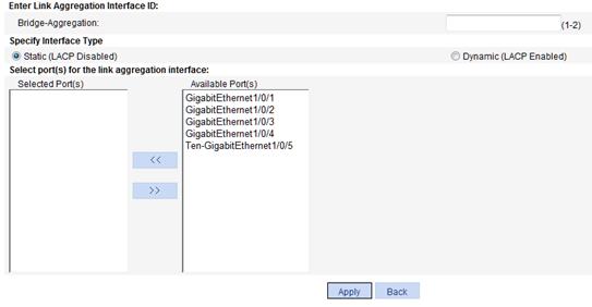
3. Configure a link aggregation group, as described in Table 26.
4. Click Apply.
|
Item |
Description |
|
Enter Link Aggregation Interface ID |
Assign an ID to the link aggregation group to be created. You can view the result in the Summary area at the bottom of the page. |
|
Specify Interface Type |
Set the type of the link aggregation interface to be created: · Static (LACP Disabled). · Dynamic (LACP Enabled). |
|
Select port(s) for the link aggregation interface |
Select one or multiple ports to be assigned to the link aggregation group. |
Displaying aggregate interface information
1. From the navigation tree, select Network > Link Aggregation.
The Summary tab is displayed by default. The list on the upper part of the page displays information about all the aggregate interfaces.
2. Select an aggregate interface from the list.
The list on the lower part of the page displays detailed information about the member ports of the associated link aggregation group.
Figure 78 Displaying aggregate interface information

Table 27 Field description
|
Field |
Description |
|
Aggregation interface |
Type and ID of the aggregate interface. Bridge-Aggregation represents a Layer 2 aggregate interface. |
|
Link Type |
Type of the aggregate interface: · Static. · Dynamic. |
|
Partner ID |
ID of the remote device, containing its LACP priority and MAC address. |
|
Selected Ports |
Number of Selected ports in each link aggregation group. Only Selected ports can transmit and receive user data. |
|
Standby Ports |
Number of Unselected ports in each link aggregation group. Unselected ports cannot transmit or receive user data. |
|
Member Port |
Member ports of the aggregate interface. |
|
State |
Selected states of the member ports: · Selected. · Unselected. |
|
Reason for being Unselected |
Reason why the state of a member port is Unselected. For a selected member port, this field displays a hyphen (-). |
Setting LACP priority
1. From the navigation tree, select Network > LACP.
2. Click Setup.
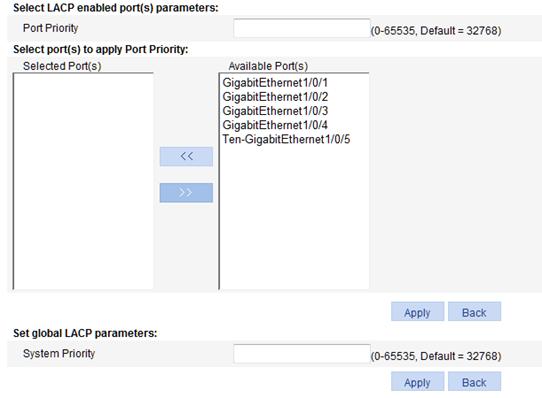
3. In the Set LACP enabled port(s) parameters area, set the port priority, and select the desired ports.
4. Click Apply in the area.
|
Item |
Description |
|
Port Priority |
Set the LACP priority. |
|
Select port(s) to apply Port Priority |
Select the ports for which you want to set the LACP priority. You can set the LACP priority for both LACP-enabled ports and LACP-disabled ports. |
5. In the Set global LACP parameters area, set the system priority.
6. Click Apply in the area.
Displaying LACP-enabled port information
1. From the navigation tree, select Network > LACP.
The Summary tab is displayed by default. The upper part of the page displays a list of all LACP-enabled ports on the device and information about them. Table 29 describes the fields.
2. From the port list, select a port.
3. Click View Details.
Detailed information about the peer port appears on the lower part of the page. Table 30 describes the fields.
Figure 80 Displaying LACP-enabled port information

Table 29 Field description for local ports
|
Field |
Description |
|
Unit |
Member device ID in an IRF. |
|
Port |
Port where LACP is enabled. |
|
LACP State |
State of LACP on the port. |
|
Port Priority |
LACP priority of the port. |
|
State |
Active state of the port. If a port is Selected, its state is active and the ID of the aggregation group it belongs to will be displayed. |
|
Inactive Reason |
Reason code indicating why a port is inactive (or Unselected) for receiving/transmitting user data. For the meanings of the reason codes, see the bottom of the page shown in Figure 80. |
|
Partner Port |
Name of the peer port. |
|
Partner Port State |
State information of the peer port: · A—Indicates that LACP is enabled. · B—Indicates that LACP short timeout has occurred. If B does not appear, it —Indicates that LACP long timeout has occurred. · C—Indicates that the link is considered aggregatable by the sending system. · D—Indicates that the link is considered as synchronized by the sending system. · E—Indicates that the sending system considers that collection of incoming frames is enabled on the link. · F—Indicates that the sending system considers that distribution of outgoing frames is enabled on the link. · G—Indicates that the receive state machine of the sending system is using the default operational partner information. · H—Indicates that the receive state machine of the sending system is in expired state. |
|
Oper Key |
Operational key of the local port. |
Table 30 Field description for peer ports
|
Field |
Description |
|
Unit |
Number of the partner system. |
|
Port |
Name of the peer port. |
|
Partner ID |
LACP priority and MAC address of the partner system. |
|
Partner Port Priority |
LACP priority of the peer port. |
|
Partner Oper Key |
Operational key of the peer port. |
Link aggregation and LACP configuration example
Network requirements
As shown in Figure 81, aggregate the ports on each device to form a link aggregation group, balancing incoming/outgoing traffic across the member ports.
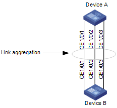
Configuration procedure
You can create a static or dynamic link aggregation group to achieve load balancing.
Method 1: Create a static link aggregation group
1. From the navigation tree, select Network > Link Aggregation.
2. Click Create.
3. Configure static link aggregation group 1:
a. Enter link aggregation interface ID 1.
b. Select the Static (LACP Disabled) option for the aggregate interface type.
c. Select GigabitEthernet 1/0/1, GigabitEthernet 1/0/2, and GigabitEthernet 1/0/3.
4. Click Apply.
Figure 82 Creating static link aggregation group 1

Method 2: Create a dynamic link aggregation group
1. From the navigation tree, select Network > Link Aggregation.
2. Click Create.
3. Configure dynamic aggregation group 1:
a. Enter link aggregation interface ID 1.
b. Select the Dynamic (LACP Enabled) option for aggregate interface type.
c. Select GigabitEthernet 1/0/1, GigabitEthernet 1/0/2, and GigabitEthernet 1/0/3.
4. Click Apply.
Figure 83 Creating dynamic link aggregation group 1
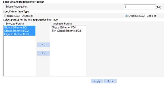
Configuring DNS
Overview
Domain Name System (DNS) is a distributed database used by TCP/IP applications to translate domain names into corresponding IP addresses. With DNS, you can use simple domain names in some applications and the DNS server translates them into correct IP addresses.
There are two types of DNS services: static and dynamic. After a user specifies a name, the device checks the local static name resolution table for an IP address. If no IP address is available, it contacts the DNS server for dynamic name resolution, which takes more time than static name resolution. Therefore, to improve efficiency, frequently queried name-to-IP address mappings are stored in the local static name resolution table.
Static domain name resolution
Static domain name resolution requires you to set up mappings between domain names and IP addresses manually. IP addresses of the corresponding domain names can be found in the static domain resolution table when you use applications such as telnet.
Dynamic domain name resolution
Dynamic domain name resolution is implemented by querying the DNS server.
DNS proxy
A DNS proxy forwards DNS requests and replies between DNS clients and a DNS server.
A DNS client considers the DNS proxy as the DNS server and sends a DNS request to the DNS proxy. The DNS proxy forwards the request to the designated DNS server, and conveys the reply from the DNS server to the client.
The DNS proxy simplifies network management. When the DNS server address is changed, you only need to change the configuration on the DNS proxy, instead of on each DNS client.
For more information about DNS, see "About the H3C Access Controllers Web-Based Configuration Guide."
Recommended configuration procedure
Configuring static name resolution table
|
Task |
Remarks |
|
Required. By default, no host name-to-IP address mappings are configured in the static domain name resolution table. |
Configuring dynamic domain name resolution
|
Step |
Remarks |
|
Required. This function is disabled by default. |
|
|
Required. Not configured by default. |
|
|
Optional. Not configured by default. |
|
|
Optional. |
Configuring DNS proxy
|
Step |
Remarks |
|
Required. By default, the device is not a DNS proxy. |
|
|
Required. Not configured by default. |
Configuring static name resolution table
1. From the navigation tree, select Network > DNS.
The default static domain name resolution configuration page appears, as shown in Figure 84.
Figure 84 Static domain name resolution configuration page

2. Click Add.
Figure 85 Creating a static domain name resolution entry

3. Configure the parameters, as described in Table 31.
4. Click Apply.
|
Item |
Description |
|
Host Name |
Configure the mapping between a host name and an IP address in the static domain mane table. Each host name corresponds to only one IP address. If you configure multiple IP addresses for a host name, the most recently configured IP address takes effect.. |
|
Host IP Address |
Configuring dynamic domain name resolution
1. From the navigation tree, select Network > DNS.
2. Click the Dynamic tab.
3. Select the Enable option for Dynamic DNS.
4. Click Apply.
Figure 86 Dynamic domain name resolution configuration page

Configuring DNS proxy
1. From the navigation tree, select Network > DNS.
2. Click the Dynamic tab to enter the page, as shown in Figure 86.
3. Select the Enable option for DNS Proxy.
4. Click Apply.
Adding a DNS server address
1. From the navigation tree, select Network > DNS.
2. Click the Dynamic tab to enter the page, as shown in Figure 86.
3. Click Add IP to enter the page, as shown in Figure 87.
4. In the DNS Server IP Address field, enter an IP address.
5. Click Apply.
Figure 87 Adding a DNS server address
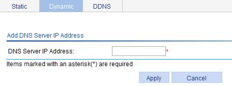
Adding a domain name suffix
1. From the navigation tree, select Network > DNS.
2. Click the Dynamic tab to enter the page, as shown in Figure 86.
3. Click Add Suffix to enter the page, as shown in Figure 88.
4. In the DNS Domain Name Suffix field, enter a DNS suffix.
5. Click Apply.
Figure 88 Adding a domain name suffix
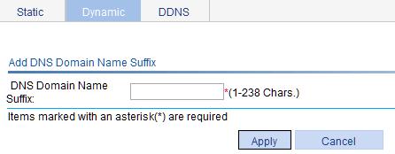
Clearing dynamic DNS cache
1. From the navigation tree, select Network > DNS.
2. Click the Dynamic tab to enter the page, as shown in Figure 86.
3. Select the Clear Dynamic DNS cache box.
4. Click Apply.
DNS configuration example
Network requirements
As shown in Figure 89, the AC wants to access the host by using a simple domain name rather than an IP address, and to request the DNS server on the network for an IP address by using dynamic domain name resolution. The IP address of the DNS server is 2.1.1.2/16 and the DNS server has a com domain, which stores the mapping between domain name host and IP address 3.1.1.1/16.
AC serves as a DNS client, and uses dynamic domain name resolution and the suffix to access the host with the domain name host.com and the IP address 3.1.1.1/16.
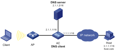
|
|
NOTE: · Before performing the following configuration, make sure the AC and the host are reachable to each another, and the IP addresses of the interfaces are configured. See Figure 89. · This configuration varies by DNS servers. The following configuration is performed on a PC running Windows Server 2000. |
Configuring the DNS server
1. Create zone com:
a. Select Start > Programs > Administrative Tools > DNS.
b. As shown in Figure 90, right click Forward Lookup Zones and select New Zone.
c. Follow the instructions to create a new zone named com.
Figure 90 Creating a zone

2. Create a mapping between host name and IP address:
a. In Figure 91, right click zone com, and then select New Host.

b. In the dialog box shown in Figure 92, enter host name host and IP address 3.1.1.1.
c. Click Add Host.
Figure 92 Adding a mapping between domain name and IP address
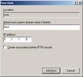
Configuring the AC
1. Enable dynamic domain name resolution.
a. Select Network > DNS from the navigation tree.
b. Click the Dynamic tab
c. Select the Enable option for Dynamic DNS.
d. Click Apply.
Figure 93 Enabling dynamic domain name resolution
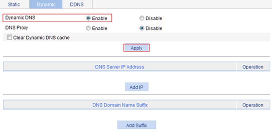
2. Configure the DNS server address:
a. Click Add IP in Figure 93 to enter the page for adding a DNS server IP address.
b. Enter 2.1.1.2 for DNS Server IP Address.
c. Click Apply.
Figure 94 Adding a DNS server address
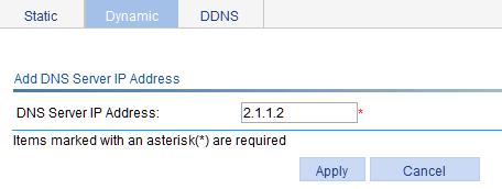
3. Configure the domain name suffix:
· Click Add Suffix in Figure 93.
· Enter com for DNS Domain Name Suffix.
· Click Apply.
Figure 95 Adding a DNS domain name suffix

Verifying the configuration
Use the ping host command on the AC to verify that the communication between the AC and the host is normal and that the corresponding destination IP address is 3.1.1.1.
1. Select Diagnostic Tools > Ping from the navigation tree to enter the IPv4 Ping configuration page.
2. Enter host in the Destination IP address or host name field.
3. Click Start to execute the ping command
4. View the result in the Summary field.
Figure 96 Ping operation
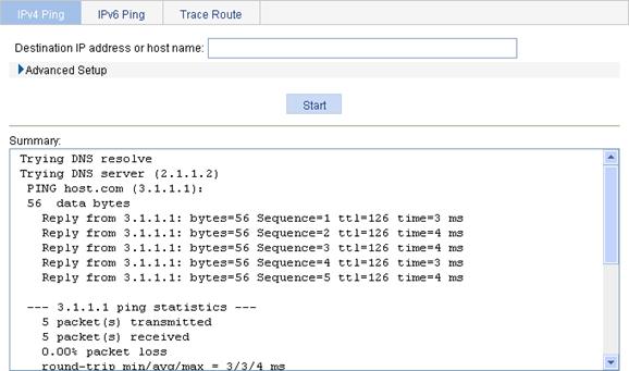
Configuring DDNS
Support for DDNS depends on the device model. For more information, see "About the H3C Access Controllers Web-Based Configuration Guide."
Overview
DNS allows you to access nodes in networks using their domain names. However, it provides only the static mappings between domain names and IP addresses. When you use a domain name to access a node whose IP address has changed, your access fails because DNS leads you to the IP address where the node no longer resides.
Dynamic Domain Name System (DDNS) dynamically updates the mappings between domain names and IP addresses for DNS servers. Through DDNS, you can always access the latest IP address corresponding to a domain name.
As shown in Figure 97, DDNS works on the client-server model.
· DDNS client—A device that needs the DNS server to update the mapping between the domain name and IP address of the device dynamically. An Internet user typically uses a domain name to access a server that provides application layer services, such as an HTTP server or an FTP server. When the IP address of such a server changes, the server runs as a DDNS client and sends a request to the DDNS server for updating the mapping between the domain name and the IP address.
· DDNS server—Informs the DNS server of latest mappings. After it receives the mapping update request from a DDNS client, the DDNS server tells the DNS server to re-map between the domain name and IP address of the DDNS client. Therefore, the Internet users can use the same domain name to access the DDNS client even if the IP address of the DDNS client has changed.
Figure 97 DDNS networking application
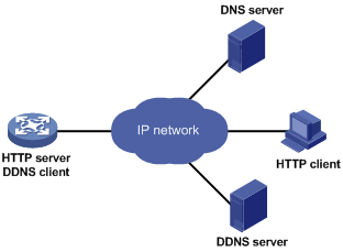
The DDNS update process does not have a unified standard and depends on the DDNS server that the DDNS client contacts. The well-known DDNS service providers include www.3322.org, www.oray.cn (also known as the PeanutHull server), and www.dyndns.com.
With the DDNS client configured, a device can dynamically update the latest mapping between its domain name and IP address on the DNS server through DDNS servers at www.3322.org or www.oray.cn for example.
Configuration prerequisites
· Visit the website of a DDNS service provider, register an account, and apply for a domain name for the DDNS client. When the DDNS client updates the mapping between the domain name and the IP address through the DDNS server, the DDNS server checks whether the account information is correct and whether the domain name to be updated belongs to the account.
· Specify the primary IP address and the security zone for the interface that is configured with DDNS and make sure the DDNS server and the interface can reach each other.
· Configure static or dynamic domain name resolution to translate the domain name of the DDNS server into an IP address.
Configuration procedure
1. From the navigation tree, select Network > DNS > DDNS.
The DDNS configuration page appears, as shown in Figure 98.
Figure 98 DDNS configuration page
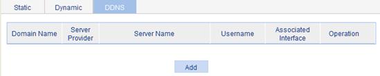
2. Click Add.
The page for creating a DDNS entry appears, as shown in Figure 99.
Figure 99 Creating a DDNS entry
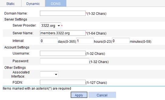
3. Configure DDNS, as described in Table 32.
4. Click Apply.
|
Item |
Description |
|
|
Domain Name |
Specify the DDNS entry name, which uniquely identifies the DDNS entry. |
|
|
Server settings |
Server Provider |
Select the DDNS server provider, which can be 3322.org or PeanutHull. |
|
Server Name |
Specify the DDNS server's domain name. After a server provider is selected, its DDNS server domain name appears automatically:. · If the server provider is 3322.org, the server domain name is members.3322.org. H3C recommends that you do not change the server name. · If the server provider is PeanutHull, the server domain name is phservice2.oray.net. The server names provided by PeanutHull include phservice2.oray.net, phddns60.oray.net, client.oray.net, and ph031.oray.net. Change the server name as needed. |
|
|
Interval |
Specify the interval for sending DDNS update requests after DDNS update is enabled.
· A DDNS update request is immediately initiated when the primary IP address of the interface changes or the link state of the interface changes from Down to Up, no matter whether the interval expires. · If you specify the interval as 0 day-0 hour-0 minute, your device does not periodically initiate any DDNS update request, but initiate a DDNS update request when the primary IP address of the interface is changed or when the link state of the interface changes from Down to Up. |
|
|
Account settings |
Username |
Specify the username used for logging in to the DDNS server. |
|
Password |
Specify the password used for logging in to the DDNS server. |
|
|
Other settings |
Associated Interface |
Select an interface to which the DDNS policy is applied. The IP address in the host name-to-IP address mapping for update is the primary IP address of the interface.
You can bind up to four DDNS entries to an interface. |
|
FQDN |
Specify the FQDN in the IP-to-FQDN mapping for update. The FQDN is the only identification of a node in the network. An FQDN consists of a local host name and a parent domain name and can be translated into an IP address. · If the DDNS service is provided by www.3322.org, the FQDN must be specified. Otherwise, DDNS update might fail. · If the DDNS server is a PeanutHull server and no FQDN is specified, the DDNS server updates all the corresponding domain names of the DDNS client account. If an FQDN is specified, the DDNS server updates only the specified IP-to-FQDN mapping. |
|
DDNS configuration example
Network requirements
The AC is a Web server with the domain name whatever.3322.org.
The AC acquires its IP address through DHCP. Through DDNS service provided by www.3322.org, the AC informs the DNS server of the latest mapping between its domain name and IP address.
The IP address of the DNS server is 1.1.1.1. the AC uses the DNS server to translate www.3322.org into the corresponding IP address.
Figure 100 Network diagram
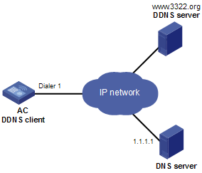
Configuring the AC
Before configuring DDNS on the AC, register at http://www.3322.org/ (account name: steven and password: nevets), add the AC's host name-to-IP address mapping to the DNS server, and make sure the devices are reachable to each other.
1. Enable dynamic domain name resolution:
a. Select Network > DNS > Dynamic from the navigation tree.
b. Select the Enable option for Dynamic DNS, as shown in Figure 101.
c. Click Apply.
Figure 101 Enabling dynamic domain name resolution

2. Configure the DNS server IP address:
a. Select Network > DNS > Dynamic from the navigation tree.
The page for enabling dynamic domain name resolution appears, as shown in Figure 101.
b. Click Add IP.
c. Enter 1.1.1.1 for DNS Server IP Address, as shown in Figure 102.
d. Click Apply.
Figure 102 Configuring the DNS server IP address
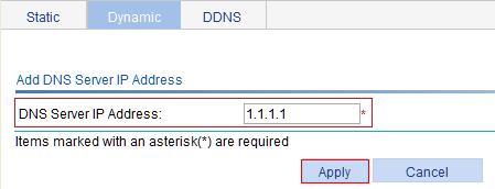
3. Configure DDNS:
a. Select Network > DNS > DDNS from the navigation tree.
b. Click Add.
The page for configuring DDNS appears.
c. Enter 3322 for Domain Name, select 3322.org from the Server Provider list, enter steven for Username, enter nevets for Password, select Dialer 1 from the Associated Interface list, and enter whatever.3322.org for FQDN.
d. Click Apply.
Figure 103 Configuring DDNS
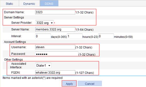
Verifying the configuration
After the preceding configuration is completed, the AC notifies the DNS server of its new domain name-to-IP address mapping through the DDNS server provided by www.3322.org whenever its IP address changes. Therefore, the AC can always provide Web service at whatever.3322.org.
Configuring PPPoE
Support for PPPoE depends on the device model. For more information, see "About the H3C Access Controllers Web-Based Configuration Guide."
Overview
Point-to-Point Protocol over Ethernet (PPPoE) uses the client/server model. It establishes point-to-point links over Ethernet, and encapsulates PPP packets in Ethernet frames.
APs configured as PPPoE clients can be connected to the Internet through a remote access device, and access control and accounting can be implemented on a per-AP basis.
PPPoE undergoes two phases:
· Discovery phase—Where a PPPoE session is initiated. In this phase, the client obtains the MAC address of the access end and generates the PPPoE session ID.
· PPP session phase—Where PPP packets are encapsulated in Ethernet frames before being sent to the peer.
In the frame, the session ID must be the one determined in the discovery phase, the MAC address must be that of the peer, and the PPP packet section begins from the Protocol ID field. In the session phase, either end of the link can terminate the session by sending PPPoE Active Discovery Terminate (PADT) packets.
For more information about PPPoE, see RFC 2516.
Figure 104 PPPoE application scenario
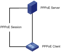
Configuration guidelines
The dialer interfaces that you create on the page by selecting Device > Interface Management can also be displayed on the PPPoE client page. On this page, you can modify or remove these dialer interfaces as well. However, you cannot establish PPPoE sessions for them.
Configuring a PPPoE client
1. From the navigation tree, select Network > PPPoE.
The system automatically enters the Client page.
Figure 105 PPPoE client information

2. Click Add.
The page for creating a PPPoE client appears.
Figure 106 Creating a PPPoE client
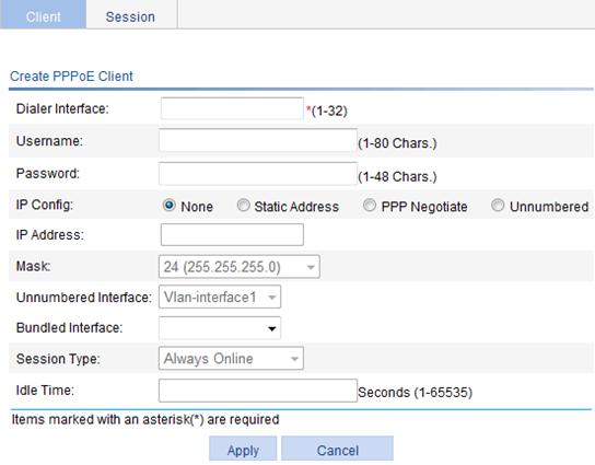
3. Configure the parameters for the PPPoE client, as described in Table 33.
4. Click Apply.
|
Task |
Remarks |
|
Dialer Interface |
Configure the number of the dialer interface. |
|
Username |
Configure the username and password used by the PPPoE client in authentication. The username and password must be configured together, or not configured at all. |
|
Password |
|
|
IP Config |
Configure the way the dialer interface obtains its IP address: · None—Does not configure an IP address. · Static Address—Statically configures an IP address and subnet mask for the interface. · PPP Negotiate—Obtains an IP address through PPP negotiation. · Unnumbered—Borrows the IP address of another interface on the same device. |
|
IP Address |
Configure an IP address and subnet mask for the dialer interface. If you select Static Address for the dialer interface, you must configure both items. |
|
Mask |
|
|
Unnumbered Interface |
Interfaces on the same device whose IP addresses are borrowed. If you select Unnumbered for the dialer interface, you must configure this item. |
|
Bundled Interface |
Configure the interfaces bound to the PPPoE client. |
|
Session Type |
Set the session type of the PPPoE client: · Always Online—When the physical link is up, the device immediately initiates a PPPoE call to establish a PPPoE session. The PPPoE session continues to exist until you delete it. · Not Always Online—When the physical link is up, the device does not initiate a PPPoE call unless there is data to be transmitted on the link. When the PPPoE link stays in idle state longer than the timeout timer set by the user, the device terminates the current PPPoE session automatically. When you select the non-permanent connection mode, you must set an idle-timeout timer. |
|
Idle Time |
Set an idle-timeout timer for the PPPoE link. This item is required when you set the session type to Not Always Online. |
Displaying PPPoE client session statistic information
1. From the navigation tree, select Network > PPPoE.
2. Click the Session tab.
The page for displaying the session information appears.
3. Select Statistic Information for Information Type, as shown in Figure 107.
4. Display PPPoE client session statistic information, as described in Table 34.
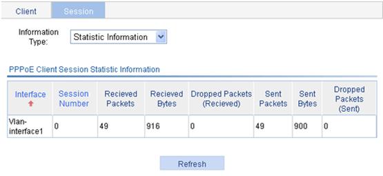
|
Field |
Description |
|
Interface |
Ethernet interface where the PPPoE session belongs. This field is null when the PPPoE session is bundled with a VLAN interface. |
|
Session Number |
PPPoE session ID. |
|
Received Packets |
Number of received packets in the PPPoE session. |
|
Received Bytes |
Number of received bytes in the PPPoE session. |
|
Dropped Packets (Received) |
Number of dropped packets which are received in the PPPoE session. |
|
Sent Packets |
Number of transmitted packets in the PPPoE session. |
|
Sent Bytes |
Number of transmitted bytes in the PPPoE session. |
|
Dropped Packets (Sent) |
Number of dropped packets which are transmitted in the PPPoE session. |
Displaying PPPoE client session information
1. From the navigation tree, select Network > PPPoE.
2. Click the Session tab.
The page for displaying the session information appears.
3. Select Summary Information for Information Type, as shown in Figure 108.
4. Displaying PPPoE client session information, as described in Table 35.

|
Field |
Description |
|
Session Number |
PPPoE session ID. |
|
Dialer Interface Number |
Number of the dialer interface corresponding to the PPPoE session. |
|
Interface |
Ethernet interface where the PPPoE session belongs. This field is null when the PPPoE session is bundled with a VLAN interface. |
|
Client-MAC |
MAC address of the PPPoE client. |
|
Server-MAC |
MAC address of the PPPoE server. |
|
Status |
PPPoE session state: · IDLE—PPPoE client negotiation is not performed. · PADI—PADI packets have been sent. The interface is waiting for the PADO response. · PADR—PADR packets have been sent. The interface is waiting for the PADS response. · PPPNEG—PPP negotiation is started. · PPPUP—PPP negotiation is completed. |
PPPoE client configuration example
Network requirements
Configure PPPoE client on the AC and enable the PPPoE client to communicate with the PPPoE server, as shown in Figure 109.

Configuring the PPPoE client
1. Configure the PPPoE client:
a. Select Network > PPPoE from the navigation tree.
The system automatically enters the Client page.
b. Click Add.
The page for creating a PPPoE client appears, as shown in Figure 110.
c. Enter 1 as the dialer interface name.
d. Enter user1 as the username.
e. Enter hello as the password.
f. Select PPP Negotiate for IP config.
g. Select Vlan-interface1 for Bundled Interface.
h. Select Always Online for Session Type.
i. Click Apply.
Figure 110 Creating a PPPoE client
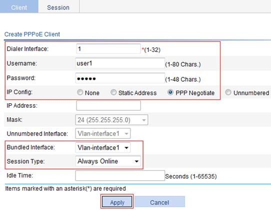
2. Configure the PPPoE server:
You must enable the PPPoE protocol on the PPPoE server, configure the PPPoE username and password that are the same as those configured on the PPPoE client, and assign an IP address to the peer end of the PPP connection. (Details not shown.)
Verifying the configuration
To display the summary information of the PPPoE session on an AC:
1. From the navigation tree of the AC, select Network > PPPoE, and click the Session tab.
2. Select Summary Information for Information Type.
Figure 111 shows that the PPP session is completed.
Figure 111 Displaying the summary information of PPPoE of sessions

Managing services
Overview
The service management module provides the following types of services: FTP, Telnet, SSH, SFTP, HTTP and HTTPS. You can enable or disable the services as needed to enhance the performance and security of the system, and achieve secure management of the device.
The service management module also provides the function to modify HTTP and HTTPS port numbers, and the function to associate the FTP, HTTP, or HTTPS service with an ACL, which reduces attacks of illegal users on these services.
FTP service
The File Transfer Protocol (FTP) is an application-layer protocol for sharing files between server and client over a TCP/IP network.
Telnet service
The Telnet protocol is an application layer protocol that provides remote login and virtual terminal functions on the network.
SSH service
Secure Shell (SSH) offers an approach to securely log in to a remote device. It protects devices against attacks such as IP spoofing and plain text password interception using encryption and authentication.
SFTP service
The secure file transfer protocol (SFTP) is a new feature in SSH2.0. SFTP uses the SSH connection to provide secure data transfer. The device can serve as the SFTP server, allowing a remote user to log in to the SFTP server for secure file management and transfer. The device can also serve as an SFTP client, enabling a user to login from the device to a remote device for secure file transfer.
HTTP service
The Hypertext Transfer Protocol (HTTP) is used for transferring Web page information across the Internet. It is an application-layer protocol in the TCP/IP protocol suite.
You can log in to the device using the HTTP protocol with HTTP service enabled, accessing and controlling the device with Web-based network management.
HTTPS service
The Hypertext Transfer Protocol Secure (HTTPS) refers to the HTTP protocol that supports the Security Socket Layer (SSL) protocol.
The SSL protocol of HTTPS enhances the security of the device in the following ways:
· Uses the SSL protocol to ensure legal clients' secure access to the device and prohibit illegal clients.
· Encrypts the data exchanged between the HTTPS client and the device to ensure the data security and integrity.
· Defines certificate attribute-based access control policy for the device to control the access right of the client, to avoid attacks from illegal clients.
Configuring service management
1. From the navigation tree, select Network > Service.
The service management configuration page appears.
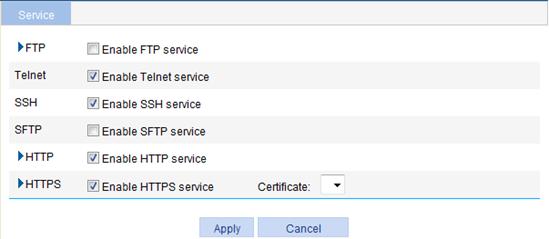
2. Enable or disable various services on the page, as described in Table 36.
3. Click Apply.
|
Item |
Description |
|
|
FTP |
Enable FTP service |
Specify whether to enable the FTP service. The FTP service is disabled by default. |
|
ACL |
Associate the FTP service with an ACL. Only the clients that pass the ACL filtering are permitted to use the FTP service. You can view this configuration item by clicking the expanding button in front of FTP. |
|
|
Telnet |
Enable Telnet service |
Specify whether to enable the Telnet service. The Telnet service is enabled by default. |
|
SSH |
Enable SSH service |
Specify whether to enable the SSH service. The SSH service is disabled by default. |
|
SFTP |
Enable SFTP service |
Specify whether to enable the SFTP service. The SFTP service is disabled by default.
When you enable the SFTP service, the SSH service must be enabled. |
|
HTTP |
Enable HTTP service |
Specify whether to enable the HTTP service. The HTTP service is enabled by default. |
|
Port Number |
Set the port number for HTTP service. You can view this configuration item by clicking the expanding button in front of HTTP.
When you modify a port, make sure the port is not used by another service. |
|
|
ACL |
Associate the HTTP service with an ACL. Only the clients that pass the ACL filtering are permitted to use the HTTP service. You can view this configuration item by clicking the expanding button in front of HTTP. |
|
|
HTTPS |
Enable HTTPS service |
Specify whether to enable the HTTPS service. The HTTPS service is disabled by default. |
|
Certificate |
Select a local certificate for the HTTPS service from the Certificate dropdown list. You can configure the certificates available in the dropdown list in Authentication > Certificate Management. For more information, see "Managing certificates."
· The service management, portal authentication, and local EAP service modules always reference the same PKI domain. Changing the referenced PKI domain in any of the three modules also changes the PKI domain referenced in the other two modules. · If no certificate is specified, the HTTPS service generates its own certificate. |
|
|
Port Number |
Set the port number for HTTPS service. You can view this configuration item by clicking the expanding button in front of HTTPS.
When you modify a port, make sure the port is not used by another service. |
|
|
ACL |
Associate the HTTPS service with an ACL. Only the clients that pass the ACL filtering are permitted to use the HTTPS service. You can view this configuration item by clicking the expanding button in front of HTTPS. |
|
Using diagnostic tools
Ping
You can use the ping function to check whether a device with a specified address is reachable, and to examine network connectivity.
A successful execution of the ping command includes the following steps:
1. The source device sends an ICMP echo request (ECHO-REQUEST) to the destination device.
2. The destination device responds by sending an ICMP echo reply (ECHO-REPLY) to the source device after receiving the ICMP echo request.
3. The source device displays related statistics after receiving the reply.
Output of the ping command includes the following:
· The ping command can be applied to the destination's host name or IP address. If the destination's host name is unknown, the prompt information is displayed.
· If the source device does not receive an ICMP echo reply within the timeout time, it displays the prompt information and the statistics during the ping operation. If the source device receives an ICMP echo reply within the timeout time, it displays the number of bytes of the echo reply, the message sequence number, Time to Live (TTL), the response time, and the statistics during the ping operation. Statistics displayed during the ping operation include number of packets sent, number of echo reply messages received, percentage of messages not received, and the minimum, average, and maximum response time.
Trace route
By using the trace route command, you can display the Layer 3 devices involved in delivering a packet from source to destination. In the event of network failure, this function can identify failed nodes.
The trace route command includes the following steps in its execution:
1. The source device sends a packet with a TTL value of 1 to the destination device.
2. The first hop (the Layer 3 device that first receives the packet) responds by sending a TTL-expired ICMP message to the source, with its IP address encapsulated. In this way, the source device can obtain the address of the first Layer 3 device.
3. The source device sends a packet with a TTL value of 2 to the destination device.
4. The second hop responds with a TTL-expired ICMP message, which gives the source device the address of the second Layer 3 device.
5. This process continues until the ultimate destination device is reached. In this way, the source device can trace the addresses of all the Layer 3 devices involved in reaching the destination device.
The traceroute command can be applied to the destination's host name or IP address. If the destination's host name is unknown, the prompt information is displayed.
Ping operation
IPv4 ping operation
1. From the navigation tree, select Diagnostic Tools > Ping.
The IPv4 Ping configuration page appears.
2. Click the expansion button before Advanced Setup to display the configurations of the advanced parameters of IPv4 ping operation.
Figure 113 IPv4 ping configuration page
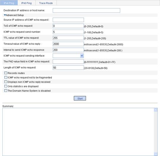
3. In the Destination IP address or host name field, enter the IPv4 address or host name of the destination device.
4. Set the advanced parameters for the IPv4 ping operation.
5. Click Start to execute the ping command.
6. View the result in the Summary field.
Figure 114 IPv4 ping operation results
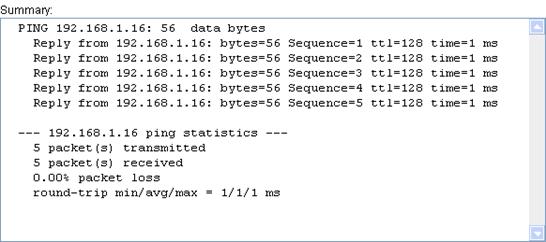
IPv6 ping operation
1. From the navigation tree, select Diagnostic Tools > Ping.
2. Click the IPv6 Ping tab.
The IPv6 ping configuration page appears.
3. Expand Advanced Setup to display the configurations of the advanced parameters of IPv6 ping operation.

4. In the Destination IP address or host name field, enter the IPv6 address or host name of the destination device.
5. Set the advanced parameters for the IPv6 ping operation.
6. Click Start to execute the ping command.
7. View the result in the Summary field.
Figure 116 IPv6 ping operation results
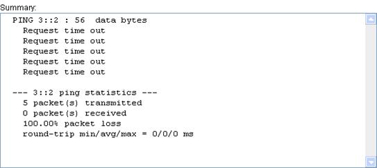
Trace route operation
The Web interface does not support trace route on IPv6 addresses.
Before performing the trace route operations, execute the ip ttl-expires enable command on the intermediate device to enable the sending of ICMP timeout packets and the ip unreachables enable command on the destination device to enable the sending of ICMP destination unreachable packets.
To perform a traceroute operation:
1. From the navigation tree, select Diagnostic Tools > Trace Route.
2. Click the Trace Route tab.
The Trace Route configuration page appears.
Figure 117 Trace Route configuration page

3. Enter the destination IP address or host name in the field.
4. Click Start to execute the trace route command.
5. View the result in the Summary field.
Figure 118 Trace route operation results
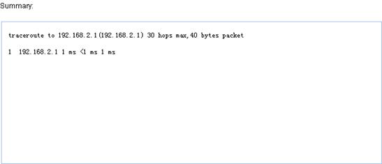
Configuring NAT
Support for NAT depends on the device model. For more information, see "About the H3C Access Controllers Web-Based Configuration Guide."
Overview
Network Address Translation (NAT) provides a way to translate an IP address in the IP packet header to another IP address. NAT enables a large number of private users to access the Internet by using a small number of public IP addresses. NAT effectively alleviates the depletion of IP addresses.
A private IP address is used only in an internal network, and a public or external IP address is used on the Internet and is globally unique.
According to RFC 1918, three blocks of IP addresses are reserved for private networks:
· Class A—10.0.0.0 through 10.255.255.255.
· Class B—172.16.0.0 through 172.31.255.255.
· Class C—192.168.0.0 through 192.168.255.255.
No host with an IP address in the above three ranges exists on the Internet. You can use those IP addresses in an enterprise network freely without requesting them from an ISP or registration center.
In addition to translating private addresses to public addresses, NAT also performs address translation between any two networks. In this document, the two networks refer to an internal network and an external network. Generally a private network is an internal network, and a public network is an external network.
Figure 119 shows the NAT operation.

1. The internal host at 192.168.1.3 sends an IP packet to the external server at 1.1.1.2 through the NAT device.
2. After receiving the packet, the NAT device checks the IP header. Finding that the packet is destined to the external network, the NAT device translates the private source IP address 192.168.1.3 to the globally unique IP address 20.1.1.1, and then forwards the packet to the external server. Meanwhile, the NAT device records the mapping between the two addresses in its NAT table.
3. The external server responds to the internal host with an IP packet whose destination IP address is 20.1.1.1. After receiving the packet, the NAT device checks the IP header, looks up its NAT table for the mapping, replaces the destination address with the private address of 192.168.1.3, and then sends the new packet to the internal host.
The NAT operation is transparent to the terminals involved. The external server believes that the IP address of the internal PC is 20.1.1.1 and is unaware of the private address 192.168.1.3. As a result, NAT hides the private network from external networks.
Despite the advantages of allowing internal hosts to access external resources and providing privacy, NAT has the following disadvantages:
· Because NAT involves translation of IP addresses, the IP headers cannot be encrypted. This is also true to the application protocol packets when the contained IP address or port number needs to be translated. For example, you cannot encrypt an FTP connection. Otherwise, its port command cannot work correctly.
· Network debugging becomes more difficult. For example, when a host in a private network tries to attack other networks, it is harder to pinpoint the attacking host because its internal IP address is hidden.
NAT control
Typically, an enterprise allows some hosts in the internal network to access external networks and prohibits others. The enterprise can achieve this through the NAT control mechanism. If a source IP address is in the denied address list, the NAT device does not translate the address. In addition, the NAT device only translates private addresses to specified public addresses.
You can achieve NAT control through an access control list (ACL) and an address pool.
· Only packets matching the ACL rules are served by NAT.
· An address pool is a collection of consecutive public IP addresses for address translation. You can specify an address pool based on the number of available public IP addresses, the number of internal hosts, and network requirements. The NAT device selects an address from the address pool as the public address of an IP packet.
NAT implementation
Basic NAT
When an internal host accesses an external network, NAT uses an external or public IP address to replace the original internal IP address. As shown in Figure 119, NAT uses the IP address of the outbound interface on the NAT device. All internal hosts use the same external IP address to access external networks and only one host can access external networks at a given time.
A NAT device can also hold multiple public IP addresses to support concurrent access requests. Whenever a new external network access request comes from the internal network, NAT chooses an available public IP address (if any) to replace the source IP address, forwards the packet, and records the mapping between the two addresses. In this way, multiple internal hosts can access external networks simultaneously.
The number of public IP addresses that a NAT device needs is usually far less than the number of internal hosts because not all internal hosts access external networks at the same time. The number of public IP addresses is related to the number of internal hosts that might access external networks simultaneously during peak hours.
NAPT
Network Address Port Translation (NAPT) is a variation of basic NAT. It allows multiple internal addresses to be mapped to the same public IP address, which is called multiple-to-one NAT.
NAPT mapping is based on both the IP address and the port number. With NAPT, packets from multiple internal hosts are mapped to the same external IP address with different port numbers.
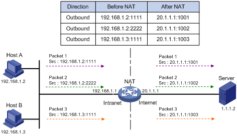
As shown in Figure 120, three IP packets arrive at the NAT device. Packets 1 and 2 are from the same internal address but have different source port numbers. Packets 1 and 3 are from different internal addresses but have the same source port number. NAPT maps their source IP addresses to the same external address but with different source port numbers. Therefore, the packets can still be discriminated. When response packets arrive, the NAT device can forward them to corresponding hosts based on the destination addresses and port numbers.
NAPT can better utilize IP address resources, enabling more internal hosts to access the external network at the same time.
Easy IP
Easy IP uses the public IP address of an interface on the device as the translated source address to save IP address resources, and uses ACLs to permit only certain internal IP addresses to be NATed.
Internal server
NAT hides the internal network structure and the identities of internal hosts. However, some internal hosts such as an internal Web server or FTP server might need to be accessed by external hosts. NAT satisfies this need by supporting internal servers.
You can configure an internal server on the NAT device by mapping a public IP address and port number to the private IP address and port number of the internal server. For example, you can configure an address like 20.1.1.12:8080 as an internal Web server's external address and port number.
In Figure 121, when the NAT device receives a packet destined for the public IP address of an internal server, it looks up the NAT entries and translates the destination address and port number in the packet to the private IP address and port number of the internal server. When the NAT device receives a response packet from the internal server, it translates the source private IP address and port number of the packet into the public IP address and port number of the internal server.
Figure 121 Internal server operation
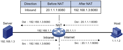
DNS mapping
Generally, the DNS server and users that need to access internal servers reside on the public network. You can specify an external IP address and a port number for an internal server on the public network interface of a NAT device, so that external users can access the internal server using its domain name or pubic IP address. As shown in Figure 122, an internal host wants to access an internal Web server by using its domain name, and the DNS server is located on the public network. Typically, the DNS server replies with the public address of the internal server to the host and thus the host cannot access the internal server. The DNS mapping feature can solve the problem.
Figure 122 Diagram for NAT DNS mapping operation
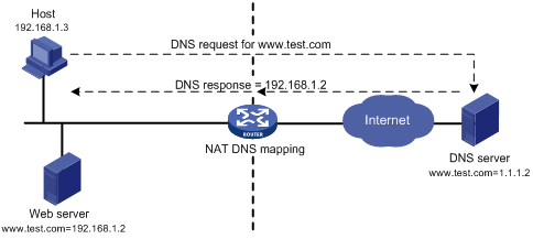
A DNS mapping entry records the domain name, public address, public port number, and protocol type of an internal server. After receiving a DNS reply, the NAT-enabled interface matches the domain name in the message against the DNS mapping entries. If a match is found, the interface replaces the public IP address in the reply with the private IP address of the internal server. Then, the host can use the private address to access the internal server.
Low-priority address pool
An address pool is a set of consecutive public IP addresses used for dynamic NAT. A NAT gateway selects addresses from the address pool and uses them as the translated source IP addresses.
To implement NAT for stateful failover (asymmetric-path), you must configure the same address pool on both devices so that one device can take over when the other device fails. However, if the two devices select the same IP address from their address pool and assign the same port number, reverse sessions on the two devices are the same. As a result, they cannot back up session data.
To solve the problem, the low-priority address pool attribute is introduced to NAT. Configure a non-low-priority address pool on a device and configure a low-priority address pool on the other device. The two address pools have the same address range, but have different port number ranges so that the devices can back up session data.
For more information about stateful failover, see "Configuring stateful failover."
Configuration guidelines
When you configure address pools, follow these guidelines:
· On certain types of devices, an address pool cannot include IP addresses in other address pools, IP addresses of interfaces with Easy IP enabled, or public IP addresses of internal servers.
· Low-priority address pools cannot include IP addresses in non low-priority address pools, external IP addresses for one-to-one NAT, and public IP addresses of internal servers.
· The address pool, dynamic NAT, static NAT, and internal server configurations can be modified through Web pages. The modification you make takes effect after the former configuration is removed by the system.
Recommended configuration procedure
Configuring address translation
A NAT device can be configured with or dynamically generate mapping entries to translate between internal and external network addresses. Address translation can be classified into dynamic and static NAT.
Dynamic NAT
A dynamic NAT entry is generated dynamically. Dynamic NAT is implemented by associating an ACL with an address pool (or the address of an interface in the case of Easy IP). This association defines what packets can use the addresses in the address pool (or the interface's address) to access the external network. Dynamic NAT is applicable when a large number of internal users must access external networks. An IP address is selected from the associated address pool to translate an outgoing packet. After the session terminates, the selected IP address is released.
Table 37 Dynamic NAT configuration task list
|
Task |
Remarks |
|
Required for configuring NAPT and many-to-many NAT. |
|
|
Required. Configure dynamic NAT on an interface. |
Static NAT
Mappings between external and internal network addresses are manually configured. Static NAT can meet fixed access requirements of a few users.
Table 38 Static NAT configuration task list
|
Task |
Remarks |
|
Required. Static NAT supports two modes, one-to-one and net-to-net. |
|
|
Required. Configure static NAT on an interface. |
Configuring an internal server
|
Task |
Remarks |
|
Required. After you map the private IP address/port number of an internal server to a public IP address/port number, hosts in external networks can access the server located in the private network. |
|
|
Optional. The DNS mapping feature enables an internal host to use the domain name to access an internal server located on the same private network, while the DNS server resides on the public network. |
Creating an address pool
1. From the navigation tree, select Network > NAT.
The Dynamic NAT page appears.
Figure 123 Dynamic NAT
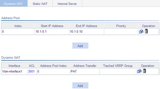
|
|
TIP: You can click the ID link of an ACL to view details about the ACL, and create and delete ACL rules. For more information about ACL configuration, see "Configuring ACLs." |
2. In the Address Pool area, click Add.
The Add NAT Address Pool page appears.
Figure 124 Adding a NAT address pool

3. Create an IP address pool, as described in Table 39.
4. Click Apply.
|
Item |
Description |
|
Index |
Specify the index of an address pool. |
|
Start IP Address |
Specify the start IP address of the address pool. |
|
End IP Address |
Specify the end IP address of the address pool. The end IP address must be identical to or higher than the start IP address. |
|
Low priority |
Configure the address pool as a low-priority or a non low-priority address pool.
This configuration item is applicable for asymmetric-path stateful failover only. The low priority settings for the local and peer devices must be different. |
Configuring dynamic NAT
1. From the navigation tree, select Network > NAT.
The Dynamic NAT page appears.
2. In the Dynamic NAT area, click Add.
The Add Dynamic NAT page appears.
Figure 125 Adding dynamic NAT
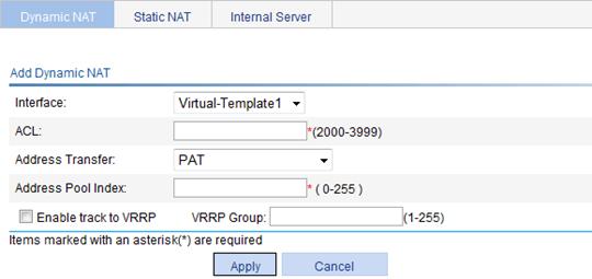
3. Configure dynamic NAT on an interface, as described in Table 40.
4. Click Apply.
|
Item |
Description |
|
Interface |
Specify an interface on which dynamic NAT is to be enabled. |
|
ACL |
Specify an ACL for dynamic NAT. You cannot associate an ACL with multiple NAT address pools, or associate an ACL with both Easy IP and an address pool.
On some devices, the rules of an ACL applied on an interface cannot conflict with one another, that is, rules with the same source IP address, destination IP address, and VPN instance are considered as a conflict. In a basic ACL (numbering 2000 to 2999), rules with the same source IP address and VPN instance are considered as a conflict. |
|
Address Transfer |
Select an address translation mode: · PAT—Refers to NAPT. In this mode, associating an ACL with an address pool translates both IP addresses and port numbers. · No-PAT—Refers to many-to-many NAT. In this mode, associating an ACL with an address pool translates only IP addresses. · Easy IP—In this mode, the NAT gateway directly uses an interface's public IP address as the translated IP address, and uses an ACL to match IP packets. Only one mode can be selected for an address pool. |
|
Address Pool Index |
Specify the index of a NAT address pool for dynamic NAT. The NAT address pool must have been configured through NAT address configuration. If Easy IP is selected for Address Transfer, you do not need to enter an address pool index. |
|
Enable track to VRRP |
Configure whether to associate dynamic NAT on an interface with a VRRP group, and specify the VRRP group to be associated if you associate dynamic NAT on an interface with a VRRP group. When two network devices implement both stateful failover and dynamic NAT, follow these guidelines: · Make sure each address pool on an interface is associated with only one VRRP group. Otherwise, the system associates the address pool with the VRRP group having the highest group ID. · To ensure normal switchovers between the two devices, you must add the devices to the same VRRP group, and associate dynamic NAT with the VRRP group. |
|
VRRP Group |
Creating a static address mapping
1. From the navigation tree, select Network > NAT, and click Static NAT.
The Static NAT page appears.

2. In the Static Address Mapping area, click Add.
The Add Static Address Mapping page appears.
Figure 127 Adding static address mapping

3. Configure a static address mapping, as described in Table 41.
4. Click Apply.
|
Item |
Description |
|
Internal IP Address |
Enter an internal IP address for the static address mapping. |
|
Global IP Address |
Enter a public IP address for the static address mapping. |
|
Mask |
Enter a mask for the IP address. |
|
ACL |
Enter an ACL ID for the static address mapping. |
Enabling static NAT on an interface
1. From the navigation tree, select Network > NAT, and click Static NAT.
The Static NAT page appears, as shown in Figure 126.
2. In the Interface Static Translation area, click Add.
The page for enabling interface static translation appears.
Figure 128 Enabling interface static translation
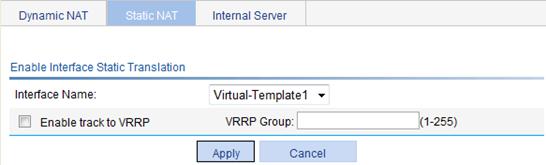
3. Enable static NAT on an interface, as described in Table 42.
4. Click Apply.
|
Item |
Description |
|
Interface Name |
Select an interface to which static NAT is applied. |
|
Enable track to VRRP |
Configure whether to associate static NAT on an interface with a VRRP group, and specify the VRRP group to be associated. When two network devices implement both stateful failover and dynamic NAT, to ensure normal switchovers between the two devices, you need to add the devices to the same VRRP group, and associate dynamic NAT with the VRRP group. |
|
VRRP Group |
Configuring an internal server
This section describes basic and advanced internal server settings. In the basic configuration page, you can specify the service type without setting internal ports, which use the default ports of services. In the advanced configuration page, you need to specify the protocol type and internal ports.
Configuring basic internal server settings
1. From the navigation tree, select Network > NAT.
2. Click the Internal Server tab.
The Internal Server page appears.
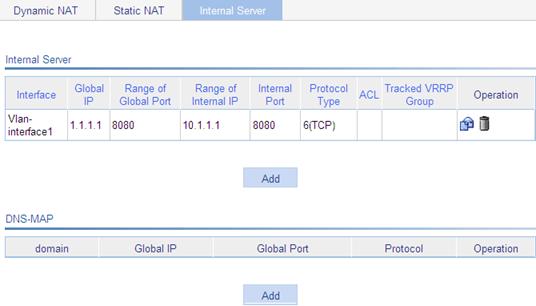
3. In the Internal Server area, click Add.
The page for adding an internal server appears.
Figure 130 Adding an internal server
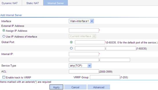
4. Configure the internal server, as described in Table 43.
5. Click Apply.
Configuring advanced internal server settings
1. Click Advanced in the page shown in Figure 130.
The Advanced Configuration page appears.
Figure 131 Internal server advanced configuration

2. Configure the internal server, as described in Table 43.
3. Click Apply.
|
Item |
Description |
|
Interface |
Specify an interface to which the internal server policy is applied. |
|
Protocol Type |
Select the protocol to be carried by IP (Only available in advanced configuration). Select from the drop-down list. For advanced configuration, if the selected protocol type is neither 6(TCP) nor 17(UDP), you can only specify a mapping between an internal IP address and an external IP address. Configuration items for internal and the global ports are not available. |
|
External IP Address |
Specify the public IP address for the internal server. You can enter an IP address, or use the IP address of an interface. |
|
Global Port |
Specify the global port numbers for the internal server. This option is available when 6(TCP) or 17(UDP) is selected as the protocol type. You can: · For basic configuration: Use the single box to specify a global port. The value of 0 represents the default port of the specified service type. If the selected service type is any(TCP) or any(UDP), the global port is any port. Use the double boxes to specify a range of global ports, which have a one-to-one correspondence with the specified range of internal IP addresses. · For advanced configuration: Set the global port only when the protocol type is 6(TCP) or 17(UDP). Use the single box to specify a fixed port and 0 represents the specified internal port. Use the double boxes to specify a range of global ports that have a one-to-one correspondence with the specified range of internal IP addresses. |
|
Internal IP |
Specify the internal IP addresses for the internal server. · For basic configuration: Use the single box to specify a fixed internal IP address if you use the single box for Global Port to set a global port. Use the double boxes to specify a range of internal IP addresses if you use the double boxes for Global Port to set a range of global ports. The specified range of internal IP addresses has a one-to-one correspondence with the specified range of global ports. The number of internal IP addresses must be identical to the number of specified global ports. · For advanced configuration: When the protocol type is neither 6(TCP) nor 17(UDP), or you specify a fixed global port in the single box for Global Port, specify a fixed internal IP address in the single box. When the protocol type is 6(TCP) or 17(UDP), and you set a range of global ports in the double boxes for Global Port, specify a range of internal IP addresses in the double boxes. The specified range of internal IP addresses has a one-to-one correspondence with the specified range of global ports. The number of internal addresses must be identical to the number of specified global ports. |
|
Internal Port |
Specify the internal port number of the internal server. (Only available in advanced configuration.) This option is available when 6(TCP) or 17(UDP) is selected for the protocol type. If you enter 0 in the field, all types of services are provided. This configuration indicates a static connection between internal addresses and external addresses. |
|
ACL |
Specify the ACL ID for the internal server. |
|
Enable track to VRRP |
Configure whether to associate the internal server on an interface with a VRRP group, and specify the VRRP group to be associated. When two network devices deliver both stateful failover and dynamic NAT, follow these guidelines: · Make sure the public address of an internal server on an interface is associated with only one VRRP group. Otherwise, the system associates the public address with the VRRP group having the highest group ID. · To ensure normal switchovers between the two devices, you need to add the devices to the same VRRP group, and associate dynamic NAT with the VRRP group. |
|
VRRP Group |
Configuring a DNS mapping
1. From the navigation tree, select Network > NAT.
2. Click the Internal Server tab.
The Internal Server page appears, as shown in Figure 129.
3. Click Add in the DNS-MAP area.
The page for adding DNS-MAP appears.
Figure 132 Adding DNS-MAP
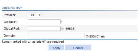
4. Configure a DNS mapping, as shown in Table 44.
5. Click Apply.
|
Item |
Description |
|
Protocol |
Select the protocol supported by an internal server. |
|
Global IP |
Specify the external IP address of the internal server. |
|
Global Port |
Specify the port number of the internal server. |
|
Domain |
Specify the domain name of the internal server. |
NAT configuration examples
Address translation configuration example
Network requirements
As shown in Figure 133, a company has three public IP addresses ranging from 202.38.1.1/24 to 202.38.1.3/24, and a private network segment of 10.110.0.0/16. Specifically, the company requires that the internal users on subnet 10.110.10.0/24 can access the Internet through NAT.
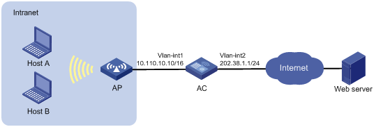
Configuring the AC
1. Configure an ACL 2001 to permit internal users in subnet 10.110.10.0/24 to access the Internet:
a. Select QoS > ACL IPv4 from the navigation tree.
b. Click Add.
c. Enter 2001 for ACL Number, as shown in Figure 134.
d. Click Apply.

e. Click the Basic Setup tab.
The page for basic setup appears.
f. Select 2001 for ACL, and Permit for Action. Select the Source IP Address box and enter 10.110.10.0. Enter 0.0.0.255 for Source Wildcard.
g. Click Add.
Figure 135 Configuring ACL 2001 to permit users on network 10.110.10.0/24 to access the Internet
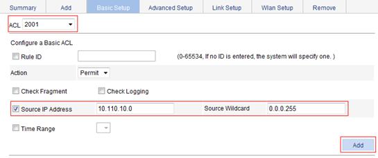
To prohibit other users to access the Internet:
a. Select Deny for Action, as shown in Figure 136.
b. Click Add.
Figure 136 Configuring ACL 2001 to prohibit other users to access the Internet
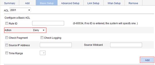
2. Configure a NAT address pool 0, including public addresses of 202.38.1.2 and 202.38.1.3.
a. Select Network > NAT from the navigation tree.
The Dynamic NAT page appears.
b. Click Add in Address Pool.
The Add NAT Address Pool page appears, as shown in Figure 137.
c. Enter 0 for Index, enter 202.38.1.2 for Start IP Address, and enter 202.38.1.3 for End IP Address.
d. Click Apply.
Figure 137 Configuring NAT address pool 0
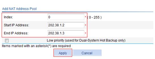
3. Configure dynamic NAT:
a. Click Add in the Dynamic NAT area.
The Add Dynamic NAT page appears.
b. Select Vlan-interface2 for Interface and enter 2001 for ACL.
c. Select PAT for Address Transfer.
d. Enter 0 for Address Pool Index.
e. Click Apply.
Figure 138 Configuring dynamic NAT
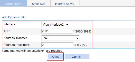
Internal server configuration example
Network requirements
As illustrated in Figure 139, a company provides two Web servers and one FTP server for external users to access. The internal network address is 10.110.0.0/16. The internal address for the FTP server is 10.110.10.3/16, for the Web server 1 is 10.110.10.1/16, and for the Web server 2 is 10.110.10.2/16. The company has three public IP addresses from 202.38.1.1/24 through 202.38.1.3/24. Specifically, the company has the following requirements:
· External hosts can access internal servers using public address 202.38.1.1/24.
· Port 8080 is used for Web server 2.
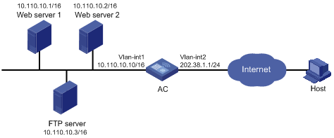
Configuring the internal server
1. Configure the FTP server:
a. Select Network > NAT from the navigation tree.
b. Click the Internal Server tab.
c. Click Add in the Internal Server area.
The Add Internal Server page appears.
d. Select Vlan-interface2 for Interface.
e. Select the Assign IP Address option, and enter 202.38.1.1.
f. Select the first option for Global Port and enter 21.
g. Enter 10.110.10.3 for Internal IP.
h. Select ftp for Service Type.
i. Click Apply.
Figure 140 Configuring an internal FTP server

2. Configure Web server 1:
a. Click Add in the Internal Server area.
The Add Internal Server page appears.
b. Select Vlan-interface2 for Interface
c. Select the Assign IP Address option, and enter 202.38.1.1.
d. Select the first option for Global Port and enter 80.
e. Enter 10.110.10.1 for Internal IP.
f. Select www for Service Type.
g. Click Apply.
Figure 141 Configuring internal Web server 1

3. Configure Web server 2:
a. Click Add in the Internal Server area.
The Add Internal Server page appears.
b. Select Vlan-interface2 for Interface
c. Select the Assign IP Address option, and enter 202.38.1.1.
d. Select the first option for Global Port and enter 8080.
e. Enter 10.110.10.2 for Internal IP.
f. Select www for Service Type.
g. Click Apply.
Figure 142 Configuring internal Web server 2
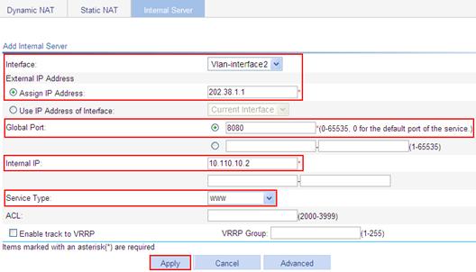
Configuring ALG
Application Level Gateway (ALG) processes the payload information of application layer packets to make sure data connections can be established.
Usually, NAT translates only IP address and port information in packet headers and does not analyze fields in application layer payloads. However, the packet payloads of some protocols might contain IP address or port information, which might cause problems if not translated. For example, an FTP application involves both data connection and control connection, and data connection establishment dynamically depends on the payload information of the control connection.
ALG can work with NAT and ASPF to implement the following functions:
· Address translation—Resolves the source IP address, port, protocol type (TCP or UDP), and remote IP address information in packet payloads.
· Data connection detection—Extracts information required for data connection establishment and establishing data connections for data exchange.
· Application layer status checking—Inspects the status of the application layer protocol in packets. Packets with correct states have their status updated and are sent for further processing, whereas packets with incorrect states are dropped.
Support for these functions depends on the application layer protocol.
ALG can process the following protocol packets:
· DNS
· FTP
· ILS
· MSN/QQ
· NBT
· PPTP
· RTSP
· SCCP
· SIP
· SQLNET, a language in Oracle
· TFTP
|
|
NOTE: Support for ALG depends on the device model. For more information, see "About the H3C Access Controllers Web-Based Configuration Guide." |
ALG process
The following example describes the FTP operation of an ALG-enabled device.
As shown in Figure 143, the host on the external network accesses the FTP server on the internal network in passive mode through the ALG-enabled device.
Figure 143 ALG-enabled FTP application in passive mode
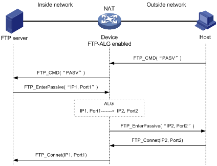
The communication process includes the following steps:
1. Establishing a control connection.
The host sends a TCP connection request to the server. If a TCP connection is established, the server and the host enter the user authentication stage.
2. Authenticating the user.
The host sends to the server an authentication request, which contains the FTP commands (user and password) and the contents.
When the request passes through the ALG-enabled device, the commands in the payload of the packet are resolved and used to check whether the protocol state transition is correctly proceeding. If not, the request will be dropped. In this way, ALG protects the server against clients that send packets with state errors or log in to the server with unauthorized user accounts.
An authentication request with the correct state is forwarded by the ALG-enabled device to the server, which authenticates the host according to the information in the packet.
3. Establishing a data connection.
If the host passes the authentication, a data connection is established between the host and the server. If the host is accessing the server in passive mode, the server sends to the host a PASV response by using its private network address and port number (IP1, Port1). When the response arrives at the ALG-enabled device, the device resolves the packet and translates the server's private network address and port number into the server's public network address and port number (IP2, Port2). Then, the device uses the public network address and port number to establish a data connection with the host.
4. Exchanging data.
The host and the FTP server exchange data through the established data connection.
Configuration procedure
By default, ALG is enabled for all protocols.
To enable ALG for protocols:
1. From the navigation tree, select Network > ALG.
The Application Layer Inspection page appears.
Figure 144 ALG configuration
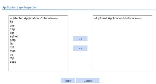
2. Add target application protocols to the Selected Application Protocols list to enable ALG for them.
3. Click Apply.
ALG configuration examples
The following examples describe only ALG-related configurations, assuming that other required configurations on the server and client have been done.
FTP ALG configuration example
Network requirements
As shown in Figure 145, a company uses the private network segment 192.168.1.0/24, and has four public network addresses: 5.5.5.1, 5.5.5.9, 5.5.5.10, and 5.5.5.11. The company wants to provide FTP services to the outside.
Configure NAT and ALG on the AC so that hosts on the external network can access the FTP server on the internal network.
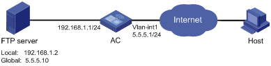
Configuration procedure
1. Enable ALG for FTP. (By default, ALG is enabled for FTP, and this step can be skipped.)
a. Select Network > ALG from the navigation tree.
b. Add ftp to the Selected Application Protocols list, as shown in Figure 146.
c. Click Apply.
Figure 146 Enabling ALG for FTP

2. Configure ACL 2001:
a. Select QoS > ACL IPv4 from the navigation tree.
b. Click the Add tab.
c. Enter 2001 for ACL Number, as shown in Figure 147.
d. Click Apply.

e. Click the Basic Setup tab.
f. Select 2001 for ACL.
g. Select Permit for Action, as shown in Figure 148.
h. Click Apply.
Figure 148 Configuring a rule for basic ACL
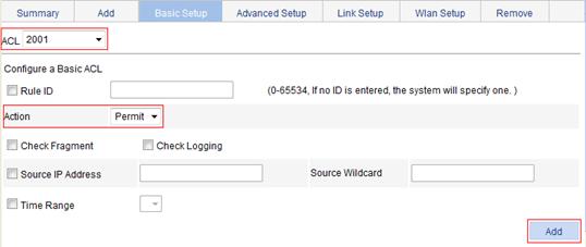
3. Configure the NAT address pool:
a. Select Network > NAT from the navigation tree.
The Dynamic NAT page appears.
b. Click Add in the Address Pool area.
The Add NAT Address Pool page appears.
c. Enter 1 for Index.
d. Enter 5.5.5.9 for Start IP Address.
e. Enter 5.5.5.11 for End IP Address.
f. Click Apply.
Figure 149 Adding a NAT address pool
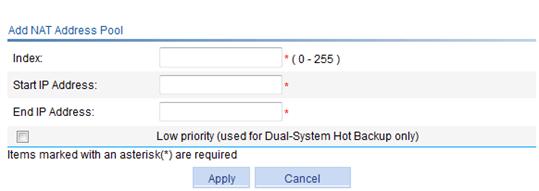
4. Configure dynamic NAT:
a. Click Add in the Dynamic NAT area.
The Add Dynamic NAT page appears.
b. Select Vlan-interface1 for Interface..
c. Enter 2001 for ACL.
d. Select PAT for Address Transfer.
e. Enter 1 for Address Pool Index.
f. Click Apply.
Figure 150 Configuring dynamic NAT
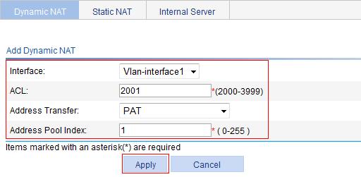
5. Configure an internal FTP server
a. Select Network > NAT from the navigation tree.
b. Click the Internal Server tab.
c. Click Add in the Internal Server area.
The Add Internal Server page appears.
d. Select Vlan-interface1 for Interface.
e. Select the Assign IP Address option, and enter 5.5.5.10.
f. Select the first option for Global Port and enter 21.
g. Enter 192.168.1.2 for Internal IP.
h. Select ftp for Service Type.
i. Click Apply.
Figure 151 Adding an internal FTP server
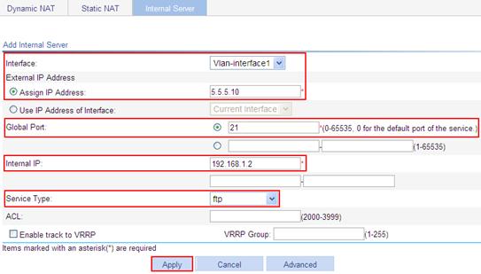
SIP ALG configuration example
Network requirements
As shown in Figure 152, a company uses the private network segment 192.168.1.0/24, and has four public network addresses: 5.5.5.1, 5.5.5.9, 5.5.5.10, and 5.5.5.11. SIP UA 1 is on the internal network and SIP UA 2 is on the outside network.
Configure NAT and ALG on the AC so that SIP UA 1 and SIP UA 2 can communicate by using their aliases. SIP UA 1 selects an IP address from the range 5.5.5.9 to 5.5.5.11 when registering with the SIP server on the external network.

Configuration procedure
1. Enable ALG for SIP. (By default, ALG is enabled for SIP, and this step can be skipped.)
a. Select Network > ALG from the navigation tree.
b. Add sip to the Selected Application Protocols list, as shown in Figure 153.
c. Click Apply.
Figure 153 Enabling ALG for SIP
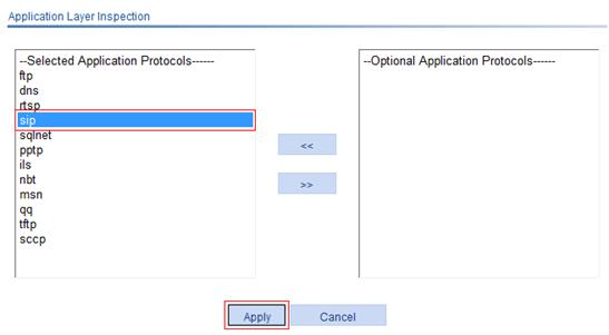
2. Configure ACL 2001:
a. Select QoS > ACL IPv4 from the navigation tree.
b. Click the Add tab.
c. Enter 2001 for ACL Number, as shown in Figure 154.
d. Click Apply.
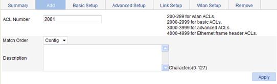
e. Click the Basic Setup tab.
f. Select 2001 for ACL, and Permit for Action. Select the Source IP Address box and enter 192.168.1.0. Enter 0.0.0.255 for Source Wildcard, as shown in Figure 148.
g. Click Add.
Figure 155 Configuring an ACL rule to permit packets sourced from 192.168.1.0/24
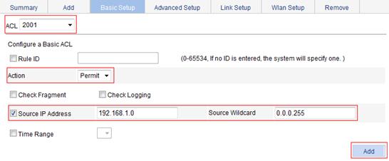
To prohibit other users to access the Internet:
a. Select Deny for Action, as shown in Figure 156.
b. Click Add.
Figure 156 Configuring an ACL rule to deny packets

3. Configure the NAT address pool:
a. Select Network > NAT from the navigation tree.
The Dynamic NAT page appears.
b. Click Add in the Address Pool area.
The Add NAT Address Pool page appears.
c. Enter 1 for Index.
d. Enter 5.5.5.9 for Start IP Address.
e. Enter 5.5.5.11 for End IP Address.
f. Click Apply.
Figure 157 Adding a NAT address pool

4. Configure dynamic NAT:
a. Click Add in the Dynamic NAT area.
The Add Dynamic NAT page appears.
b. Select Vlan-interface2 for Interface..
c. Enter 2001 for ACL.
d. Select PAT for Address Transfer.
e. Enter 1 for Address Pool Index.
f. Click Apply.
Figure 158 Configuring dynamic NAT

NBT ALG configuration example
Network requirements
As shown in Figure 159, a company using the private network segment 192.168.1.0/24 wants to provide NBT services to the outside.
Configure NAT and ALG on the AC so that Host A uses 5.5.5.9 as its external IP address, the WINS server uses 5.5.5.10 as its external IP address, and Host B can access the WINS server and Host A by using host names.

Configuration procedure
1. Enable ALG for NBT. (By default, ALG is enabled for NBT, and this step can be skipped.)
a. Select Network > ALG from the navigation tree.
b. Add nbt to the Selected Application Protocols list.
c. Click Apply.
Figure 160 Enabling ALG for NBT
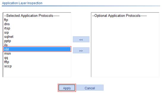
2. Configure static NAT:
a. Select Network > NAT from the navigation tree.
b. Click the Static NAT tab.
The Static NAT page appears.
c. Click Add in the Static Address Mapping area.
The Add Static Address Mapping page appears.
d. Enter 192.168.1.3 for Internal IP Address.
e. Enter 5.5.5.9 for Global IP Address.
f. Click Apply.
Figure 161 Adding a static address mapping

3. Configure static NAT for an interface:
a. Click Add in the Interface Static Translation area.
b. Select Vlan-interface2 for Interface Name, as shown in Figure 162.
c. Click Apply.
Figure 162 Configuring static NAT for an interface

4. Configure an internal WINS server:
a. Select Network > NAT > Internal Server from the navigation tree.
b. Click the Internal Server tab.
c. Click Add in the Internal Server area.
d. Click Advanced Configuration.
e. Select Vlan-interface2 for Interface.
f. Select 17(UDP) for Protocol Type.
g. Enter 5.5.5.10 as the external IP address and 137 as the global port.
h. Enter 192.168.1.2 as the internal IP address and 137 as the internal port.
i. Click Apply.
Figure 163 Configuring an internal WINS server
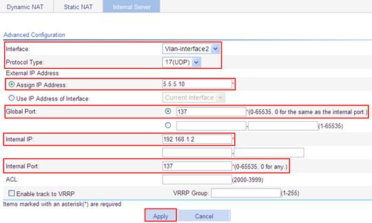
j. Click Add in the Internal Server area. Configure an interval WINS server, which is similar to the configuration shown in Figure 163.
k. Click Advanced Configuration.
l. Select Vlan-interface2 for Interface.
m. Select 17(UDP) as the protocol type.
n. Enter 5.5.5.10 as the external IP address and 138 as the global port.
o. Enter 192.168.1.2 as the internal IP address and 138 as the internal port.
p. Click Apply.
q. Click Add in the Internal Server area. Configure an interval WINS server, which is similar to the configuration shown in Figure 163.
r. Click Advanced Configuration.
s. Select Vlan-interface2 for Interface.
t. Select 6(UDP) as the protocol type.
u. Enter 5.5.5.10 as the external IP address, and 139 as the global port.
v. Enter 192.168.1.2 as the internal IP address, and 138 as the internal port.
w. Click Apply.
Configuring WAN interfaces
Overview
The WAN interfaces that you can configure on the Web interface are Ethernet interfaces.
An Ethernet interface supports the following connection modes:
· Auto—The interface acts as a DHCP client to get an IP address through DHCP.
· Manual—The IP address and subnet mask are configured manually for the interface.
· PPPoE—The interface acts as a PPPoE client. PPPoE provides access to the Internet for hosts in an Ethernet through remote access devices. It also implements access control and accounting on a per-host basis. As it is cost-effective, PPPoE gains popularity in various applications, such as residential networks.
Support for WAN interface configuration depends on the device model.
Configuring a WAN interface
1. From the navigation tree, select Interface Setup > WAN Interface Setup.
The WAN interface configuration page appears, as shown in Figure 164.
Figure 164 WAN Interface Setup
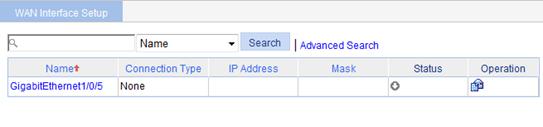
2. Click the ![]() icon for an Ethernet interface.
icon for an Ethernet interface.
The page for configuring the Ethernet interface appears, as shown in Figure 3.
Figure 165 Configuring an Ethernet interface
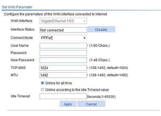
3. Configure the Ethernet interface, as described in Table 45, Table 46, and Table 47.
Table 45 Configuration items (auto mode)
|
Item |
Description |
|
WAN Interface |
Displays the name of the Ethernet interface to be configured. |
|
Interface Status |
Display and set the interface status: · Connected—Indicating that the current interface is up and connected, click Disable to shut down the interface. · Not connected—Indicating that the current interface is up, but not connected, click Disable to shut down the interface. · Administratively Down—Indicating that the current interface is shut down by a network administrator, click Enable to bring up the interface. |
|
Connect Mode: Auto |
Select Auto as the connection mode. The interface will get an IP address automatically. |
Table 46 Configuration items (manual mode)
|
Item |
Description |
|
WAN Interface |
Displays the name of the Ethernet interface to be configured. |
|
Interface Status |
Display and set the interface status: · Connected—Indicating that the current interface is up and connected, click Disable to shut down the interface. · Not connected—Indicating that the current interface is up but not connected, click Disable to shut down the interface. · Administratively Down—Indicating that the current interface is shut down by a network administrator, click Enable to bring up the interface. |
|
Connect Mode: Manual |
Select Manual as the connection mode. In this mode, you must manually assign an IP address and subnet mask to the interface. |
|
TCP-MSS |
Configure the TCP MSS on the interface. |
|
MTU |
Configure the MTU on the interface. |
|
IP Address |
Configure an IP address for the interface. |
|
IP Mask |
Configure the subnet mask for the interface. |
|
Gateway IP Address |
Configure the next hop for the static route. |
|
DNS1 |
Assign an IP address to the DNS servers. DNS1 has a higher precedence than DNS2. To configure a global DNS server, select Advanced > DNS Setup > DNS Configuration from the navigation tree. The global DNS server has a higher precedence than all the DNS servers configured on the interfaces. That is, an interface first sends a query request to the global DNS server. If failing to receive a response, it sends query requests to the DNS servers configured on the interfaces one by one. |
|
DNS2 |
Table 47 Configuration items (PPPoE mode)
|
Item |
Description |
|
WAN Interface |
Displays the name of the Ethernet interface to be configured. |
|
Interface Status |
Display and set the interface status: · Connected—Indicating that the current interface is up and connected, click Disable to shut down the interface. · Not connected—Indicating that the current interface is up but not connected, click Disable to shut down the interface. · Administratively Down—Indicating that the current interface is shut down by a network administrator, click Enable to bring up the interface. |
|
Connect Mode: PPPoE |
Select PPPoE as the connection mode. |
|
User Name |
Configure the username for authentication. |
|
Password |
Displays whether a password is configured for authentication. If the field displays null, no password is configured for authentication. |
|
New Password |
Set or modify the password for authentication. |
|
TCP-MSS |
Configure the TCP MSS on the interface. |
|
MTU |
Configure the MTU on the interface. |
|
Set the idle timeout time for a connection: · Online for all time—The connection is maintained until being disconnected manually or upon an anomaly. · Online according to the Idle Timeout value—The connection is disconnected automatically if no traffic is transmitted or received on the link for a period of time. The connection will be re-set up when an access to the Internet request is received. If you select Online according to the Idle Timeout value, you must set the Idle timeout value. |
4. Click Apply.
Displaying the general information and statistics of an interface
1. From the navigation tree, select Interface Setup > WAN Interface Setup.
The WAN interface configuration page appears, as shown in Figure 2.
2. To view the statistics of an interface, click the interface name.
Port statistics is displayed, as shown in Figure 4..
Figure 166 Statistics of an interface