- Table of Contents
-
- H3C Access Controllers Web-Based Configuration Guide(E3703P61 R2509P61 R3709P61 R2609P61 R3509P61)-6W103
- 00-Preface
- 01-About
- 02-Web overview
- 03-Login
- 04-Quick Start
- 05-Summary
- 06-Device
- 07-Network
- 08-AP Configuration
- 09-Wireless Service
- 10-WLAN Roaming Configuration
- 11-Radio Configuration
- 12-Authentication
- 13-Security
- 14-QoS Configuration
- 15-Advanced Settings
- 16-Stateful Failover Configuration
- 17-VPN
- 18-SSL VPN Configuration
- Related Documents
-
| Title | Size | Download |
|---|---|---|
| 17-VPN | 779.07 KB |
Relationship between IKE and IPsec
Recommended configuration procedure
Configuring global IKE parameters
Recommended configuration procedure
Configuring an IPsec policy template
Applying an IPsec policy group
Configuring IKE
Support for VPN depends on the device model. For more information, see About the H3C Access Controllers Configuration Guides.
Overview
Built on a framework defined by the ISAKMP, IKE provides automatic key negotiation and SA establishment services for IPsec. This simplifies the application, management, configuration and maintenance of IPsec dramatically.
Instead of transmitting keys directly across a network, IKE peers transmit keying materials between them, and calculate shared keys, respectively. Even if a third party captures all exchanged data for calculating the keys, it cannot calculate the keys.
Unless otherwise specified, the term "IKE" in this chapter refers to the IKE version 1 protocol.
IKE security mechanism
IKE has a series of self-protection mechanisms, and it supports secure identity authentication, key distribution, and IPsec SA establishment on insecure networks.
Data authentication
Data authentication involves the following concepts:
· Identity authentication—Mutual identity authentication between peers. Two authentication methods are available: pre-shared key authentication and PKI-based digital signature authentication (RSA signature).
· Identity protection—Encrypts the identity information with the generated keys before sending the information.
DH
The DH algorithm is a public key algorithm. With this algorithm, two peers can exchange keying material and then use the material to calculate the shared keys. Due to the decryption complexity, a third party cannot decrypt the keys even after intercepting all keying materials.
PFS
The PFS feature is a security feature based on the DH algorithm. By making sure keys have no derivative relations, it guarantees a broken key brings no threats to other keys. For IPsec, PFS is implemented by adding an additional key exchange at IKE negotiation phase 2.
IKE operation
IKE negotiates keys and establishes SAs for IPsec in two phases:
1. Phase 1—Two peers establish an ISAKMP SA, a secure, authenticated channel for communication. In this phase, two modes are available: main mode and aggressive mode.
2. Phase 2—Using the ISAKMP SA established in phase 1, the two peers negotiate to establish IPsec SAs.
Figure 1 IKE exchange process in main mode

As shown in Figure 1, the main mode of IKE negotiation in phase 1 involves three pairs of messages:
· SA exchange—Used for negotiating the security policy.
· Key exchange—Used for exchanging the Diffie-Hellman public value and other values like the random number. Key data is generated in this stage.
· ID and authentication data exchange—Used for authentication of identity and exchanged data in phase 1.
The main difference between main mode and aggressive mode is that aggressive mode does not provide identity protection and only exchanges the above three messages. Aggressive mode exchanges less information and features higher negotiation speed. It applies to scenarios where the requirement for identity protection is lower. For scenarios with higher requirement for identity protection, use the main mode.
Functions of IKE in IPsec
IKE provides the following functions for IPsec:
· Automatically negotiates IPsec parameters such as the keys, reducing the manual configuration complexity.
· Performs DH exchange whenever establishing an SA, making sure each SA has a key independent of any other keys.
· Automatically negotiates SAs when the sequence number in the AH or ESP header overflows, ensuring that IPsec provides the anti-replay service normally by using the sequence number.
· Provides end-to-end dynamic authentication.
· Identity authentication and management of peers influence IPsec deployment. A large-scale IPsec deployment needs the support of CAs or other institutes that manage identity data centrally.
Relationship between IKE and IPsec
Figure 2 Relationship between IKE and IPsec
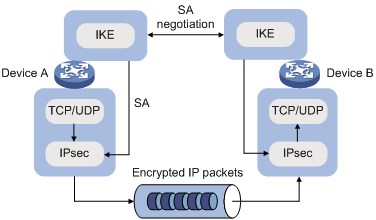
Figure 2 illustrates the relationship between IKE and IPsec:
· IKE is an application layer protocol using UDP and functions as the signaling protocol of IPsec.
· IKE negotiates SAs for IPsec and delivers negotiated parameters and generated keys to IPsec.
· IPsec uses the SAs set up through IKE negotiation for encryption and authentication of IP packets.
Protocols and standards
· RFC 2408, Internet Security Association and Key Management Protocol (ISAKMP)
· RFC 2409, The Internet Key Exchange (IKE)
· RFC 2412, The OAKLEY Key Determination Protocol
Configuration prerequisites
Before you configure IKE, verify the following parameters:
· The strength of the algorithms for IKE negotiation (the security protection level), including the identity authentication method, encryption algorithm, authentication algorithm, and DH group. Different algorithms provide different levels of protection. A stronger algorithm means more resistant to decryption of protected data but requires more resources. Generally, the longer the key, the stronger the algorithm.
· The pre-shared key or the PKI domain to which the certificate belongs. For more information about PKI configuration, see "Managing certificates."
Recommended configuration procedure
|
Step |
Remarks |
|
Optional. Configure the IKE local name and NAT keepalive interval. |
|
|
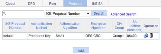
Required when IKE peers need to specify an IKE proposal. An IKE proposal defines a set of attributes describing how IKE negotiation should take place. You may create multiple IKE proposals with different preferences. The preference of an IKE proposal is represented by its sequence number, and the smaller the sequence number, the higher the preference. Two peers must have at least one pair of matched IKE proposals for successful IKE negotiation. During IKE negotiation, the negotiation initiator sends its IKE proposals to the peer. The peer will match the IKE proposals against its own IKE proposals, starting with the one with the smallest sequence number. The match goes on until a match is found or all IKE proposals are found mismatched. The matched IKE proposals will be used to establish the security tunnel. Two matched IKE proposals have the same encryption algorithm, authentication method, authentication algorithm, and DH group. The ISAKMP SA lifetime will take the smaller one of the two matched IKE proposals. By default, there is an IKE proposal, which has the lowest preference and uses these default settings: · Pre-shared key authentication method. · SHA authentication algorithm. · DES-CBC encryption algorithm. · DH group named Group1. · SA lifetime of 86400 seconds. |
|
|
Optional. DPD irregularly detects dead IKE peers. When the local end sends an IPsec packet, DPD checks the time the last IPsec packet was received from the peer. If the time exceeds the DPD interval, it sends a DPD hello to the peer. If the local end receives no DPD acknowledgement within the DPD packet retransmission interval, it retransmits the DPD hello. If the local end still receives no DPD acknowledgement after having made the maximum number of retransmission attempts (two by default), it considers the peer already dead, and clears the IKE SA and the IPsec SAs based on the IKE SA. |
|
|
Required. Create an IKE peer and configure the related parameters.
If you change the settings of an IKE peer, make sure you clear the established IPsec SAs and ISAKMP SAs on the pages displayed after you select VPN > IKE > IKE SA and select VPN > IPSec > IPSec SA, respectively. Otherwise, SA renegotiation will fail. |
|
|
Optional. View the summary information of the current ISAKMP SA. |
Configuring global IKE parameters
1. From the navigation tree, select VPN > IKE.
The IKE Global Configuration page appears.
Figure 3 IKE global configuration page
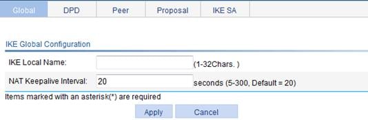
2. Configure global IKE parameters, as described in Table 1.
3. Click Apply.
|
Item |
Description |
|
IKE Local Name |
Enter a name for the local security gateway. If the local device acts as the IKE negotiation initiator and uses the ID type of FQDN or the user FQDN of the security gateway for IKE negotiation, you must configure this parameter on the local device. Then, the local device sends its gateway name as identification to its peer and the peer uses the locally configured remote gateway name to authenticate the local device. Make sure that the local gateway name configured here is identical to the remote gateway name configured on its peer. By default, the device name is used as the local gateway name. |
|
NAT Keepalive Interval |
Set the interval at which the ISAKMP SA sends NAT keepalive packets to its peer. NAT mappings on a NAT gateway may get aged. If no packet traverses an IPsec tunnel in a certain period of time, the NAT mapping will be deleted, disabling the tunnel beyond the NAT gateway from transferring data. To prevent NAT mappings from being aged, an ISAKMP SA sends to its peer NAT keepalive packets at a certain interval to keep the NAT session alive. |
Configuring an IKE proposal
1. From the navigation tree, select VPN > IKE.
2. Click the Proposal tab.
The IKE proposal list page appears.
The IKE Proposal Configuration page appears.
Figure 5 Adding an IKE proposal

4. Configure the IKE proposal parameters, as described in Table 2.
5. Click Apply.
|
Item |
Description |
|
IKE Proposal Number |
Enter the IKE proposal number. The number also stands for the priority of the IKE proposal, with a smaller value meaning a higher priority. During IKE negotiation, the system matches IKE proposals in order of proposal number, starting from the smallest one. |
|
Authentication Method |
Select the authentication method to be used by the IKE proposal. Options include: · Preshared Key—Uses the pre-shared key method. · RSA Signature—Uses the RSA digital signature method. |
|
Authentication Algorithm |
Select the authentication algorithm to be used by the IKE proposal. Options include: · SHA1—Uses HMAC-SHA1. · MD5—Uses HMAC-MD5. |
|
Encryption Algorithm |
Select the encryption algorithm to be used by the IKE proposal. Options include: · DES-CBC—Uses the DES algorithm in CBC mode and 56-bit keys for encryption. · 3DES-CBC—Uses the 3DES algorithm in CBC mode and 168-bit keys for encryption. · AES-128—Uses the AES algorithm in CBC mode and 128-bit keys for encryption. · AES-192—Uses the AES algorithm in CBC mode and 192-bit keys for encryption. · AES-256—Uses the AES algorithm in CBC mode and 256-bit keys for encryption. |
|
DH Group |
Select the DH group to be used in key negotiation phase 1. Options include: · Group1—Uses the 768-bit Diffie-Hellman group. · Group2—Uses the 1024-bit Diffie-Hellman group. · Group5—Uses the 1536-bit Diffie-Hellman group. · Group14—Uses the 2048-bit Diffie-Hellman group. |
|
SA Lifetime |
Enter the ISAKMP SA lifetime of the IKE proposal. Before an SA expires, IKE negotiates a new SA. As soon as the new SA is set up, it takes effect immediately and the old one will be cleared automatically when it expires.
If the SA lifetime expires, the system automatically updates the ISAKMP SA. DH calculation in IKE negotiation takes time, especially on low-end devices. Set the lifetime greater than 10 minutes to prevent the SA update from influencing normal communication. |
Configuring IKE DPD
1. From the navigation tree, select VPN > IKE.
2. Click the DPD tab.
The DPD detector list page appears.

The Add IKE DPD page appears.
Figure 7 Adding an IKE DPD detector

4. Configure the IKE DPD parameters, as described in Table 3.
5. Click Apply.
|
Item |
Description |
|
DPD Name |
Enter a name for the IKE DPD. |
|
DPD Query Triggering Interval |
Enter the interval after which DPD is triggered if no IPsec protected packets is received from the peer. |
|
DPD Packet Retransmission Interval |
Enter the interval after which DPD packet retransmission will occur if no DPD response is received. |
Configuring an IKE peer
1. From the navigation tree, select VPN > IKE.
2. Click the Peer tab.
The IKE peer list page appears.

The Add IKE Peer page appears.
Figure 9 Adding an IKE peer

4. Configure the IKE peer parameters, as described in Table 4.
5. Click Apply.
|
Item |
Description |
|
Peer Name |
Enter a name for the IKE peer. |
|
IKE Negotiation Mode |
Select the IKE negotiation mode in phase 1, which can be Main or Aggressive.
· If you configure one end of an IPsec tunnel to obtain an IP address dynamically, the IKE negotiation mode must be Aggressive. In this case, SAs can be established as long as the username and password are correct. · The specified negotiated mode is used when the local peer is the negotiation initiator. When acting as the responder, the negotiation mode of the initiator is used. |
|
Local ID Type |
Select the local ID type for IKE negotiation phase 1. Options include: · IP Address—Uses an IP address as the ID in IKE negotiation. · FQDN—Uses the FQDN type as the ID in IKE negotiation. If this option is selected, type a name string without any at sign (@) for the local security gateway, for example, foo.bar.com. · User FQDN—Uses a user FQDN type as the ID in IKE negotiation. If this option is selected, type a name string with an at sign (@) for the local security gateway, for example, [email protected].
In main mode, only the ID type of IP address can be used in IKE negotiation and SA establishment. |
|
Local IP Address |
Enter the IP address of the local security gateway. By default, it is the primary IP address of the interface referencing the security policy. Configure this item when you want to specify a special address for the local security gateway.
Normally, you do not need to specify the local IP address unless you want to specify a special address, such as the loopback interface address. For the local peer to act as the initiator, you must configure the remote security gateway name or IP address, so that the initiator can find the remote peer during the negotiation. |
|
Remote Gateway Address |
Enter the IP address or host name of the remote security gateway. · IP Address—Specify an IP address or a range of IP addresses for the remote gateway. If the local end is the initiator of IKE negotiation, it can have only one remote IP address and its remote IP address must match the local IP address configured on its peer. If the local end is the responder of IKE negotiation, it can have more than one remote IP address and one of its remote IP addresses must match the local IP address configured on its peer. · Hostname—Enter the host name of the remote gateway, which is the only identifier of the IPsec peer in the network. The host name can be resolved into an IP address by the DNS server. If host name is used, the local end can serve as the initiator of IKE negotiation. |
|
Remote Gateway Name |
Enter the name of the remote security gateway. If the local ID type configured for the IKE negotiation initiator is FQDN or user FQDN, the initiator sends its gateway name (IKE Local Name) to the responder for identification. The responder then uses the locally configured remote gateway name to authenticate the initiator. Make sure that the remote gateway name configured here is identical to the local gateway name (IKE Local Name) configured on its peer. |
|
Pre-Shared Key PKI Domain |
To use the authentication method of pre-shared key, select Pre-Shared Key and enter consistent pre-shared keys in the Key and Confirm Key fields. To use the authentication method of RSA signature, select PKI Domain and then select the PKI domain to which the certificate belongs in the following list. Available PKI domains are those configured on the page you enter by selecting VPN > Certificate Manager > Domain from the navigation tree. |
|
Enable DPD |
Select the IKE DPD to be applied to the IKE peer. |
|
Enable the NAT traversal function |
Enable the NAT traversal function for IPsec/IKE. The NAT traversal function must be enabled if a NAT security gateway exists in an IPsec/IKE VPN tunnel.
To save IP addresses, ISPs often deploy NAT gateways on public networks to allocate private IP addresses to users. In this case, one end of an IPsec/IKE tunnel may have a public address while the other end may have a private address, and NAT traversal must be configured at the private network side to set up the tunnel. |
Viewing IKE SAs
1. From the navigation tree, select VPN > IKE.
2. Click the IKE SA tab.
The IKE SA list page appears.
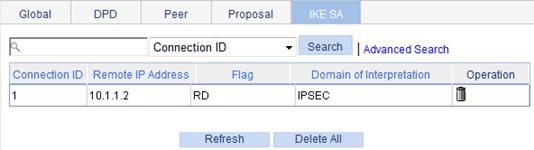
You can click Delete All to remove all ISAKMP SAs. To clear a local IPsec SA, the local end must send a Delete Message to the remote end over the corresponding ISAKMP SA. The message notifies the remote end to delete the IPsec SA. If the corresponding ISAKMP SA does not exist, the local end cannot notify the remote end to clear the IPsec SA.
Table 5 Field description
|
Field |
Description |
|
Connection ID |
Identifier of the ISAKMP SA. |
|
Remote IP Address |
Remote IP address of the SA. |
|
Flag |
Status of the SA. Possible values include: · RD—Ready. The SA has already been established and is ready for use. · ST—Stayalive. The local end is the tunnel negotiation initiator. · RL—Replaced. The tunnel has been replaced and will be cleared soon. · FD—Fading. The soft lifetime expires but the tunnel is still in use. The tunnel will be deleted when the hard lifetime expires. · TO—Timeout. The SA has received no keepalive packets after the last keepalive timeout. If no keepalive packets are received before the next keepalive timeout, the SA will be deleted.
IKE maintains the link status of an ISAKMP SA by keepalive packets. Generally, if the peer is configured with the keepalive timeout, you must configure the keepalive packet transmission interval on the local end. If the peer receives no keepalive packet during the timeout interval, the ISAKMP SA will be tagged with the TIMEOUT tag (if it does not have the tag), or be deleted along with the IPsec SAs it negotiated (when it has the tag already). |
|
Domain of Interpretation |
Interpretation domain to which the SA belongs. |
IKE configuration example
Network requirements
As shown in Figure 11, configure an IPsec tunnel between AC 1 and AC 2 to protect traffic between subnet 10.1.1.0/24 and subnet 10.1.2.0/24.
On AC 1, configure an IKE proposal that uses the sequence number 10 and the authentication algorithm MD5. AC 2 uses the default IKE proposal.
Configure the pre-shared key authentication method.

Configuring AC 1
1. Configure IP addresses for the interfaces, and assign the interfaces to security zones. (Details not shown.)
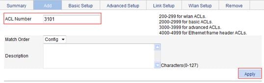
2. Create ACL 3101:
a. From the navigation tree, select QoS > ACL IPv4.
b. Click the Add tab.
c. Enter the ACL number 3101, and select the match order Config.
d. Click Apply.
Figure 12 Creating ACL 3101
e. Click the Advanced Setup tab.
f. Select the ACL 3101.
g. Select Permit from the Action list.
h. Select Source IP Address, and enter 10.1.1.0 and 0.0.0.255 as the source IP address and mask.
i. Select Destination IP Address, and enter 10.1.2.0 and 0.0.0.255 as the destination IP address and mask.
j. Click Apply.
Figure 13 Configuring a rule to allow packets from subnet 10.1.1.0/24 to subnet 10.1.2.0/24

3. Configure an IKE peer named peer:
a. From the navigation tree, select VPN > IKE.
b. Click the Peer tab.
c. Click Add.
b. Enter the peer name peer.
c. Select the negotiation mode Main.
d. Enter the remote gateway IP address 2.2.2.2.
e. Select Pre-Shared Key, and enter the pre-shared key abcde in the Key and Confirm Key fields.
f. Click Apply.
Figure 14 Configuring an IKE peer named peer

4. Create an IKE proposal numbered 10:
a. From the navigation tree, select VPN > IKE.
b. Click the Proposal tab.
c. Click Add.
c. Enter the IKE proposal number 10.
d. Select the authentication method Preshared Key.
e. Select the authentication algorithm MD5.
f. Set the SA lifetime to 5000 seconds.
g. Click Apply.
Figure 15 Creating an IKE proposal numbered 10

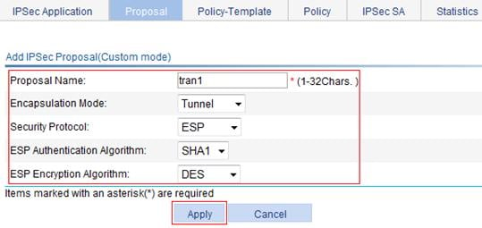
5. Create an IPsec proposal named tran1:
a. From the navigation tree, select VPN > IPSec.
b. Click the Proposal tab.
c. Click Add.
d. From the IPSec Proposal Configuration Wizard page, select Custom mode.
e. Enter the IPsec proposal name tran1.
f. Select the packet encapsulation mode Tunnel.
g. Select the security protocol ESP.
h. Select the authentication algorithm SHA1.
i. Select the encryption algorithm DES.
j. Click Apply.
Figure 16 Creating an IPsec proposal named tran1
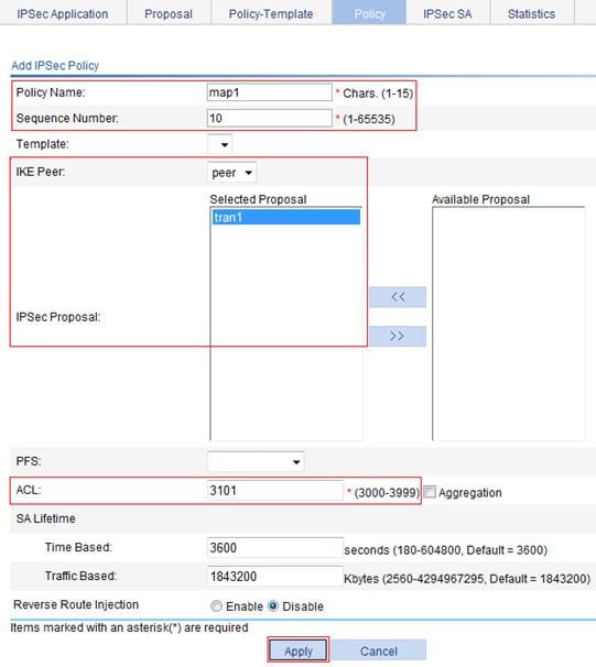
6. Create an IPsec policy named map1:
a. From the navigation tree, select VPN > IPSec.
b. Click the Policy tab.
c. Click Add.
d. Enter the IPsec policy name map1.
e. Enter the sequence number 10.
f. Select the IKE peer peer.
g. Select the IPsec proposal tran1 from the Available Proposal list, and click <<.
h. Enter the ACL number 3101.
i. Click Apply.
Figure 17 Creating an IPsec proposal named map1
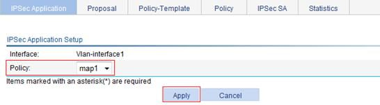
7. Apply the IPsec policy to VLAN-interface 1:
a. From the navigation tree, select VPN > IPSec.
The IPSec Application page appears.
b. Click the icon for interface Vlan-interface1.
c. Select policy map1.
d. Click Apply.
Figure 18 Applying the IPsec policy to interface VLAN-interface 1

8. Configure a static route to Host 2:
a. From the navigation tree, select Network > IPv4 Routing.
b. Click the Add tab.
c. Enter 10.1.2.0 as the destination IP address.
d. Enter 255.255.255.0 as the mask.
e. Enter 2.2.2.2 as the next hop.
f. Click Apply.
Figure 19 Configuring a static route to Host B

Configuring AC 2
1. Configure IP addresses for the interfaces, and assign the interfaces to security zones. (Details not shown.)
2. Create ACL 3101:
a. From the navigation tree, select QoS > ACL IPv4.
b. Click the Add tab.
c. Enter the ACL number 3101, and select the match order Config.
d. Click Apply.
e. Click the Advanced Setup tab.
f. Select Permit from the Action list.
g. Select Source IP Address, and enter 10.1.2.0 and 0.0.0.255 as the source IP address and mask.
h. Select Destination IP Address, and enter 10.1.1.0 and 0.0.0.255 as the destination IP address and mask.
i. Click Apply.
3. Configure an IKE peer named peer:
a. From the navigation tree, select VPN > IKE.
b. Click the Peer tab.
c. Click Add.
d. Enter the peer name peer.
e. Select the negotiation mode Main.
f. Enter the remote gateway IP address 1.1.1.1.
g. Select Pre-Shared Key, and enter the pre-shared key abcde in the Key and Confirm Key fields.
h. Click Apply.
4. Create an IPsec proposal named tran1:
a. From the navigation tree, select VPN > IPSec.
b. Click the Proposal tab.
c. Click Add.
d. From the IPSec Proposal Configuration Wizard page, select Custom mode.
e. Enter the IPsec proposal name tran1.
f. Select the packet encapsulation mode Tunnel.
g. Select the security protocol ESP.
h. Select the authentication algorithm SHA1.
i. Select the encryption algorithm DES.
j. Click Apply.
5. Create an IPsec policy named map1:
a. From the navigation tree, select VPN > IPSec.
b. Click the Policy tab.
c. Click Add.
d. Enter the IPsec policy name map1.
e. Enter the sequence number 10.
f. Select the IKE peer peer.
g. Select the IPsec proposal tran1 from the Available Proposal list, and click <<.
h. Enter the ACL number 3101.
i. Click Apply.
6. Apply the IPsec policy to VLAN-interface 1:
a. From the navigation tree, select VPN > IPSec.
The IPSec Application page appears.
b. Click the icon for interface Vlan-interface1.
c. Select policy map1.
d. Click Apply.
7. Configure a static route to Host 1:
a. From the navigation tree, select Network > IPv4 Routing.
b. Click Add.
c. Enter 10.1.1.0 as the destination IP address.
d. Enter 255.255.255.0 as the mask.
e. Enter 1.1.1.1 as the next hop.
f. Click Apply.
Verifying the configuration
After you complete the configuration, a packet destined to subnet 10.1.2.0/24 or 10.1.1.0/24 from AC 1 or AC 2 triggers IKE negotiation.
AC 1 is configured with IKE proposal 10, which uses the authentication algorithm of MD5. AC 2 uses the default IKE proposal, which uses the default authentication algorithm of SHA. Because AC 2 has no proposal matching proposal 10 of AC 1, the two devices use the default IKE proposal. The two devices do not need to have the same ISAKMP SA lifetime, and they will negotiate one instead.
Configuring IPsec
Overview
IP Security (IPsec) is a security framework defined by IETF for securing IP communications. It is a Layer 3 VPN technology that transmits data in a secure tunnel established between two endpoints.
IPsec guarantees the confidentiality, integrity, and authenticity of data and provides anti-replay service at the IP layer in an insecure network environment:
· Confidentiality—The sender encrypts packets before transmitting them over the Internet.
· Data integrity—The receiver verifies the packets received from the sender to ensure they are not tampered with during transmission.
· Data origin authentication—The receiver verifies the authenticity of the sender.
· Anti-replay—The receiver examines packets, and drops outdated or repeated packets.
IPsec delivers these benefits:
· Reduced key negotiation overheads and simplified maintenance by supporting the IKE protocol. IKE provides automatic key negotiation and automatic IPsec security association (SA) setup and maintenance.
· Good compatibility. IPsec can be applied to all IP-based application systems and services without any modification to them.
· Encryption on a per-packet rather than per-flow basis. This allows for flexibility and greatly enhances IP security.
IPsec comprises a set of protocols for IP data security, including AH, ESP, IKE, and algorithms for authentication and encryption. AH and ESP provides security services and IKE performs key exchange. For more information about IKE, see "Configuring IKE."
Basic concepts
Security protocols
IPsec comes with two security protocols:
· AH (protocol 51)—Provides data origin authentication, data integrity, and anti-replay services. For these purposes, an AH header is added to each IP packet. AH is suitable for transmitting non-critical data because it cannot prevent eavesdropping even though it works fine in preventing data tampering. AH supports authentication algorithms such as MD5 and SHA-1.
· ESP (protocol 50)—Provides data encryption in addition to origin authentication, data integrity, and anti-replay services. ESP works by inserting an ESP header and an ESP trailer in IP packets. Unlike AH, ESP encrypts data before encapsulating the data to ensure data confidentiality. ESP supports encryption algorithms such as DES, 3DES, and AES, and authentication algorithms such as MD5 and SHA-1. The authentication function is optional to ESP.
Both AH and ESP provide authentication services, but the authentication service provided by AH is stronger. In practice, you can choose either or both security protocols. When both AH and ESP are used, an IP packet is encapsulated first by ESP and then by AH.
Security association
A security association is an agreement negotiated between two communicating parties called IPsec peers. It comprises a set of parameters for data protection, including security protocols, encapsulation mode, authentication and encryption algorithms, and privacy keys and their lifetime. SAs can be set up manually or through IKE.
An SA is unidirectional. At least two SAs are needed to protect data flows in a bidirectional communication. Moreover, if two peers want to use both AH and ESP to protect data flows between them, they construct an independent SA for each protocol.
An SA is uniquely identified by a triplet, which consists of the security parameter index (SPI), destination IP address, and security protocol (AH or ESP).
An SPI is a 32-bit number for uniquely identifying an SA. It is transmitted in the AH/ESP header. A manually configured SA requires an SPI to be specified manually for it. An IKE created SA will have an SPI generated at random.
A manually configured SA never ages out. An IKE created SA has a specified period of lifetime, which comes in two types:
· Time-based lifetime—Defines how long an SA can be valid after it is created.
· Traffic-based lifetime—Defines the maximum traffic that an SA is allowed to process.
The SA becomes invalid when either of the lifetime timers expires. Before the SA expires, IKE negotiates a new SA, which takes over immediately after its creation.
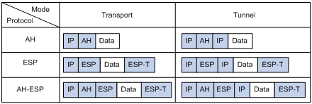
Encapsulation modes
IPsec supports the following IP packet encapsulation modes:
· Tunnel mode—IPsec protects the entire IP packet (the IP header and the payload). It uses the entire IP packet to calculate an AH or ESP header, and then encapsulates the original IP packet and the AH or ESP header with a new IP header. If you use ESP, an ESP trailer is also encapsulated. Tunnel mode typically is used for protecting gateway-to-gateway communications.
· Transport mode—IPsec protects only the IP payload. It uses only the IP payload to calculate the AH or ESP header, and inserts the calculated header between the original IP header and payload. If you use ESP, an ESP trailer is also encapsulated. The transport mode typically is used for protecting host-to-host or host-to-gateway communications.
Figure 20 shows how the security protocols encapsulate an IP packet in different encapsulation modes.
Figure 20 Encapsulation by security protocols in different modes
Authentication algorithms and encryption algorithms
· Authentication algorithms
IPsec uses hash algorithms to perform authentication. A hash algorithm produces a fixed-length digest for an arbitrary-length message. IPsec peers calculate message digests for each packet. If the resulting digests are identical, the packet is considered intact.
IPsec supports the following hash algorithms for authentication:
¡ MD5—Takes a message of arbitrary length as input and produces a 128-bit message digest.
¡ SHA-1—Takes a message of a maximum length less than the 64th power of 2 in bits as input and produces a 160-bit message digest.
Compared with SHA-1, MD5 is faster but less secure.
· Encryption algorithms
IPsec mainly uses symmetric encryption algorithms, which encrypt and decrypt data by using the same keys. The following encryption algorithms are available for IPsec on the device:
¡ DES—Encrypts a 64-bit plain text block with a 56-bit key. DES is the least secure but the fastest algorithm. It is sufficient for general security requirements.
¡ 3DES—Encrypts plain text data with three 56-bit DES keys. The key length totals up to 168 bits. It provides moderate security strength and is slower than DES.
¡ AES—Encrypts plain text data with a 128-bit, 192-bit, or 256-bit key. AES provides the highest security strength and is slower than 3DES.
IPsec SA setup modes
There are two IPsec SA setup modes:
· Manual mode—In this mode, you must manually configure and maintain all SA settings. Advanced features like periodical key update are not available. However, this mode implements IPsec independently of IKE.
· ISAKMP mode—In this mode, IKE negotiates and maintains IPsec SAs for IPsec automatically.
If the number of IPsec tunnels in your network is small, use the manual mode. If the number of IPsec tunnels is large, use the ISAKMP mode.
The Web interface supports only the ISAKMP mode.
IPsec tunnel
An IPsec tunnel is a bidirectional channel created between two peers. An IPsec tunnel comprises one or more pairs of SAs.
IPsec RRI
With IPsec Reverse Route Inject (RRI), an IPsec tunnel gateway can automatically add static routes destined for its peer IPsec tunnel gateways to a routing table.
IPsec RRI frees you from the tedious work of manually configuring and maintaining static routes for IPsec tunnels. For example, if you enable RRI on Device A in Figure 21, Device A can automatically create a static route to branch network 192.168.2.0/24 for the IPsec protected traffic from the headquarters to the branch. You do not need to add the route manually.
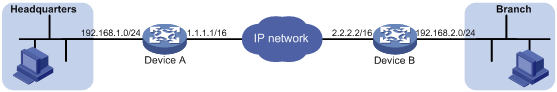
You can advertise the static routes created by IPsec RRI in the internal network. IPsec RRI can quickly create new routes for forwarding IPsec VPN traffic when an active link fails in a load balanced or stateful failover environment, or when IPsec VPN traffic cannot reach the peer gateway through the default local gateway.
IPsec RRI dynamically creates static routes based on IPsec SAs. In each static route, the destination address is the address of a protected branch network, and the next hop is the user-specified remote peer address or the remote tunnel endpoint's address learned during IPsec SA negotiation.
In an MPLS L3VPN network, an RRI-configured IPsec VPN gateway can add static routes into the IP routing table of the VPN instance that is bound to the interface applied with an IPsec policy.
IPsec RRI creates static routes when the IPsec SAs are established, and deletes the static routes when the IPsec SAs are deleted.
IPsec stateful failover
|
|
IMPORTANT: Support for this feature depends on the device model. For more information, see "About the H3C Access Controllers Web-Based Configuration Guide." |
The IPsec stateful failover function enables hot backup of IPsec service data between two devices and is usually deployed on two redundant gateways at the headquarters to improve the availability of IPsec service.
The IPsec stateful failover function must work with the stateful failover feature and the VRRP feature.
The two devices in IPsec stateful failover must join the same VRRP group to act as a single virtual device. They use the virtual IP address of the virtual device to communicate with remote devices.
The IPsec stateful failover function can operate only in standard VRRP mode. In this mode, the master processes and forwards IPsec traffic, and the backup device only synchronizes IPsec service data with the master. When the master fails, the backup immediately takes over to forward IPsec traffic. This switchover process is transparent to remote devices. No extra configuration is required on remote devices and no IPsec re-negotiation is required after the switchover.
Figure 22 IPsec stateful failover
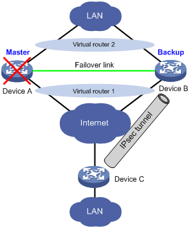
As shown in Figure 22, Device A and Device B form an IPsec stateful failover system and Device A is elected the master in the VRRP group. When Device A works normally, it establishes an IPsec tunnel to Device C, and synchronizes its IPsec service data to Device B. The synchronized IPsec service data includes the IKE SA, IPsec SAs, anti-replay sequence number and window, SA lifetime in bytes, and DPD packet sequence number. Based on the IPsec service data, Device B creates standby IKE SA and standby IPsec SAs to back up the active IKE SA and active IPsec SAs on Device A. When Device A fails, the VRRP mechanism switches IPsec traffic from Device A to Device B. Because Device B has an instant copy of Device A's IPsec service data, Device B can immediately process IPsec traffic to provide nonstop IPsec service.
Protocols and standards
· RFC 2401, Security Architecture for the Internet Protocol
· RFC 2402, IP Authentication Header
· RFC 2406, IP Encapsulating Security Payload
· RFC 4552, Authentication/Confidentiality for OSPFv3
· RFC 4301, Security Architecture for the Internet Protocol
· RFC 4302, IP Authentication Header
· RFC 4303, IP Encapsulating Security Payload (ESP)
Configuration guidelines
When you configure IPsec, follow these guidelines:
· Typically, IKE uses UDP port 500 for communication, and AH and ESP use the protocol numbers 51 and 50, respectively. You must make sure flows of these protocols are not denied on the interfaces with IKE or IPsec configured.
· If you enable both IPsec and QoS on an interface, traffic of an IPsec SA may be put into different queues by QoS, causing some packets to be sent out of order. As IPsec performs anti-replay operation, packets outside the anti-replay window in the inbound direction may be discarded, resulting in packet loss. When using IPsec together with QoS, make sure they use the same classification rules. IPsec classification rules depend on the referenced ACL rules.
Configuration considerations
You configure IPsec tunnels on the device by configuring IPsec polices. The IPsec policies use ACLs to identify protected traffic, and take effect after being applied to physical interfaces.
Configure IPsec policies by using the following steps:
1. Configure ACLs for identifying the data flows to be protected by IPsec.
2. Configure IPsec proposals to specify the security protocols, authentication and encryption algorithms, and encapsulation mode. An IPsec proposal applies to data flows associated with it.
3. Configure IPsec policies to associate data flows with IPsec proposals and specify the SA negotiation mode, the start and end points of the IPsec tunnels, the privacy keys, and the SA lifetime.
4. Apply the IPsec policies to interfaces.
Recommended configuration procedure
Configuring ACLs
For more information about ACL configuration, see "QoS > ACL IPv4," and "QoS > ACL IPv6."
If you enable both IPsec and QoS on an interface, traffic of an IPsec SA may be put into different queues by QoS, causing some packets to be sent out of order. Because IPsec performs anti-replay operation, packets outside the anti-replay window in the inbound direction may be discarded, resulting in packet loss. When using IPsec together with QoS, make sure that they use the same classification rules. IPsec classification rules depend on the referenced ACL rules. For more information about QoS classification rules, see "Configuring QoS."
When defining ACL rules for IPsec, follow these guidelines:
· Make sure that only the data flows to be protected by IPsec are defined in permit statements. If a packet is protected at the entry of the IPsec tunnel but not at the exit of the IPsec tunnel, it will be dropped.
· Avoid statement conflicts in the scope of IPsec policy groups. When creating a deny statement, be careful with its matching scope and matching order relative to permit statements. The policies in an IPsec policy group have different match priorities. ACL rule conflicts between them are prone to cause mistreatment of packets. For example, when configuring a permit statement for an IPsec policy to protect an outbound traffic flow, you must avoid the situation that the traffic flow matches a deny statement in a higher priority IPsec policy. Otherwise, the packets will be sent out as normal packets; if they match a permit statement at the receiving end, they will be dropped by IPsec.
Use of the Permit/Deny Actions in ACLs
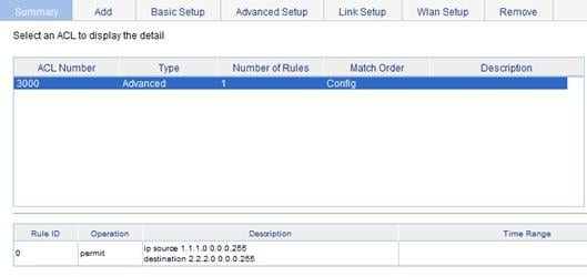
IPsec uses ACLs to identify data flows. An ACL is a collection of ACL rules. Each ACL rule is a deny or permit statement. A permit statement identifies a data flow protected by IPsec, and a deny statement identifies a data flow that is not protected by IPsec. IPsec uses referenced ACL to match against packets. The matching process stops once a match is found or ends with no match hit. The packet is handled as follows:
· Each ACL rule matches both the outbound traffic and the returned inbound traffic. Suppose there is a rule as shown in Figure 23. This rule matches both traffic from 1.1.1.0 to 2.2.2.0 and returned traffic from 2.2.2.0 to 1.1.1.0.
Figure 23 An ACL referenced in an IPsec policy
· In the outbound direction, if a permit statement is matched, IPsec considers the packet as requiring protection and continues to process it. If a deny statement is matched or no match is found, IPsec considers the packet as not requiring protection and delivers it to the next function module.
· In the inbound direction, if the packet is an IPsec packet and matches a permit statement, IPsec receives and processes the packet. If the packet is not an IPsec packet and matches a permit statement, it is discarded.
The following uses a configuration example to show how a statement conflict causes packet drop. In this example, only the ACL-related configurations are presented.
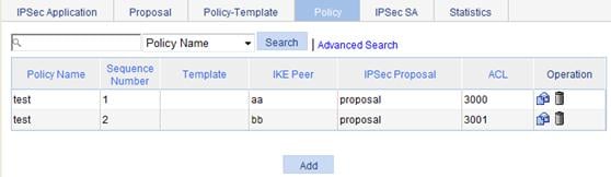
Device A connects the segment 1.1.2.0/24 and Device B connects the segment 3.3.3.0/24. On Device A, apply the IPsec policy group test to the outbound interface to Device B. The IPsec policy group contains two policies, test 1 and test 2. The ACLs referenced by the two policies each contain a rule that matches traffic from 1.1.2.0/24 to 3.3.3.0/24. The one referenced in policy test 1 is a deny statement and the one referenced in policy test 2 is a permit statement. Because test 1 is matched prior to test 2, traffic from 1.1.2.0/24 to 3.3.3.0/24 will match the deny statement and sent as normal traffic. When the traffic arrives at Device B, it will be dropped if it matches a permit statement in the ACL referenced in the applied IPsec policy.
The configurations on Device A are shown in Figure 24, Figure 25, and Figure 26.
Figure 24 ACL 3000 configuration on Device A

Figure 25 ACL 3001 configuration on Device A
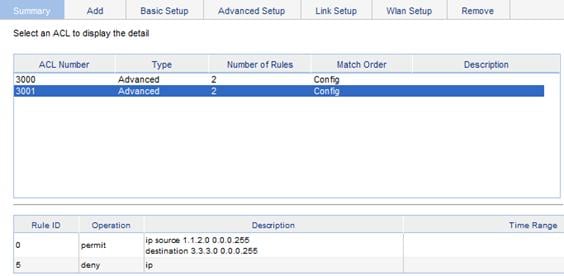
Figure 26 IPsec policy configuration on Device A
The configurations on Device B are shown in Figure 27 and Figure 28.
Figure 27 ACL 3001 configuration on Device B
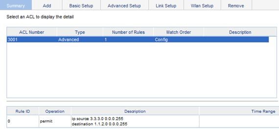
Figure 28 IPsec policy configuration on Device B

Mirror image ACLs
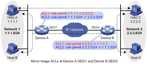
To make sure that SAs can be set up and the traffic protected by IPsec locally can be processed correctly at the remote peer, on the remote peer, create a mirror image ACL rule for each ACL rule created at the local peer. As shown in Figure 29, ACL rules on Device B are mirror images of the rules on Device A. This ensures that SAs can be created successfully for the traffic between Host A and Host C and the traffic between Network 1 and Network 2.
If the ACL rules on the peers do not form mirror images of each other, SAs can be set up only when both of the following requirements are met:
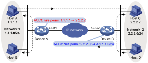
· The range specified by an ACL rule on one peer is covered by its counterpart ACL rule on the other peer. As shown in Figure 30, the range specified by the ACL rule configured on Device A is covered by its counterpart on Device B.
· The peer with the narrower rule initiates SA negotiation. If a wider ACL rule is used by the SA initiator, the negotiation request may be rejected because the matching traffic is beyond the scope of the responder. As shown in Figure 30, the SA negotiation initiated by Host A to Host C is accepted, but the SA negotiation from Host C to Host B or from Host D to Host A is rejected.
Figure 30 Non-mirror image ACLs
Protection modes
Data flows can be protected in the following modes:
· Standard mode—One tunnel is used to protect one data flow. The data flow permitted by each ACL rule is protected by one tunnel that is established separately for it.
· Aggregation mode—One tunnel is used to protect all data flows permitted by all the rules of an ACL. This mode applies to only scenarios that use IKE for negotiation.
Configuring an IPsec proposal
The Web interface provides two modes for configuring an IPsec proposal: suite mode and custom mode. The suite mode allows you to select a pre-defined encryption suite, and the custom mode allows you to configure IPsec proposal parameters discretionarily.
Configuring an IPsec proposal in suite mode
1. From the navigation tree, select VPN > IPSec.
2. Click the Proposal tab.
The IPsec proposal list page appears.

The IPSec Proposal Configuration Wizard page appears.
Figure 32 IPsec proposal configuration wizard page

4. Click Suite mode.
Figure 33 IPsec proposal configuration in suite mode
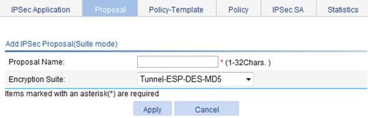
5. Enter a name for the IPsec proposal.
6. Select an encryption suite for the proposal.
An encryption suite specifies the IP packet encapsulation mode, security protocol, and authentication and encryption algorithms to be used. Available encryption suites include:
¡ Tunnel-ESP-DES-MD5—Uses the ESP security protocol, the DES encryption algorithm, and the MD5 authentication algorithm.
¡ Tunnel-ESP-3DES-MD5—Uses the ESP security protocol, the 3DES encryption algorithm, and the MD5 authentication algorithm.
¡ Tunnel-AH-MD5-ESP-DES—Uses the ESP and AH security protocols successively, making ESP use the DES encryption algorithm and perform no authentication and making AH use the MD5 authentication algorithm.
¡ Tunnel-AH-MD5-ESP-3DES—Uses the ESP and AH security protocols successively, making ESP use the 3DES encryption algorithm and perform no authentication, and making AH use the MD5 authentication algorithm.
All these suites use the tunnel mode for IP packet encapsulation.
7. Click Apply.
Configuring an IPsec proposal in custom mode
1. From the navigation tree, select VPN > IPSec.
2. Click the Proposal tab.
The IPsec proposal list page as shown in Figure 31 appears.
3. Click Add.
The IPsec proposal configuration wizard page as shown in Figure 32 appears.
4. Click Custom mode.
Figure 34 IPsec proposal configuration in custom mode
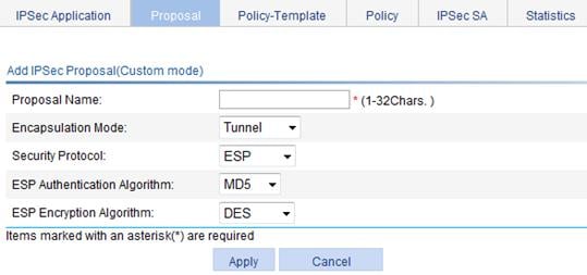
5. Configure the IPsec proposal parameters, as described in Table 6.
6. Click Apply.
|
Item |
Description |
|
Proposal Name |
Enter a name for the IPsec proposal. |
|
Encapsulation Mode |
Select an IP packet encapsulation mode for the IPsec proposal. Options include: · Tunnel—Uses the tunnel mode. · Transport—Uses the transport mode. |
|
Security Protocol |
Select a security protocol setting for the proposal. Options include: · AH—Uses the AH protocol. · ESP—Uses the ESP protocol. · AH-ESP—Uses ESP first and then AH. |
|
AH Authentication Algorithm |
Select an authentication algorithm for AH when the security protocol setting is AH or AH-ESP. Available authentication algorithms include MD5 and SHA1. |
|
ESP Authentication Algorithm |
Select an authentication algorithm for ESP when the security protocol setting is ESP or AH-ESP. You can select MD5 or SHA1, or leave it null so the ESP performs no authentication.
The ESP authentication algorithm and ESP encryption algorithm cannot be both null. |
|
ESP Encryption Algorithm |
Select an encryption algorithm for ESP when the security protocol is ESP or AH-ESP. Options include: · DES—Uses the DES algorithm and 56-bit keys for encryption. · 3DES—Uses the 3DES algorithm and 168-bit keys for encryption. · AES128—Uses the AES algorithm and 128-bit keys for encryption. · AES192—Uses the AES algorithm and 192-bit keys for encryption. · AES256—Uses the AES algorithm and 256-bit keys for encryption. · Leave it null so the ESP performs no encryption.
· Higher security means increased complexity and decreased speed. DES is sufficient for general security requirements. Use 3DES if you require high confidentiality and security. · The ESP authentication and encryption algorithms cannot be both null. |
Configuring an IPsec policy template
1. From the navigation tree, select VPN > IPSec.
2. Click the Policy-Template tab.
The IPsec policy template list page appears.
Figure 35 IPsec policy template list

The Add IPSec Template page appears.
Figure 36 Adding an IPsec policy template

4. Configure an IPsec policy template, as described in Table 7.
5. Click Apply.
|
Item |
Description |
|
|
Template Name |
Enter a name for the IPsec policy template. |
|
|
Sequence Number |
Enter a sequence number for the IPsec policy template. In an IPsec policy template group, an IPsec policy template with a smaller sequence number has a higher priority. |
|
|
IKE Peer |
Select an IKE peer for the IPsec policy template. You configure IKE peers by selecting VPN > IKE from the navigation tree. |
|
|
IPSec Proposal |
Select up to six IPsec proposals for the IPsec policy template. IPsec SAs can be set up only when the IPsec peers have at least one matching IPsec proposal. If no matching IPsec proposal is available, the IPsec SAs cannot be established, and the packets that need to be protected are discarded. |
|
|
PFS |
Enable and configure the PFS feature or disable the feature. Options include: · dh-group1—Uses the 768-bit Diffie-Hellman group. · dh-group2—Uses the 1024-bit Diffie-Hellman group. · dh-group5—Uses the 1536-bit Diffie-Hellman group. · dh-group14—Uses the 2048-bit Diffie-Hellman group.
· dh-group14, dh-group5, dh-group2, and dh-group1 are in descending order of security and calculation time. · When IPsec uses an IPsec policy configured with PFS to initiate negotiation, an additional key exchange is performed in phase 2 for higher security. · Two peers must use the same Diffie-Hellman. Otherwise, negotiation will fail. |
|
|
ACL |
Select an ACL for identifying protected traffic. The specified ACL must be created already and contains at least one rule. ACL configuration supports VPN multi-instance. Make sure that this ACL has been created and contains at least one rule. You can use an ACL to identify traffic between VPN instances. |
|
|
SA Lifetime |
Time Based |
Enter the time-based and traffic-based SA lifetime values.
When negotiating IPsec SAs, IKE uses the smaller one between the lifetime set locally and the lifetime proposed by the peer. |
|
Traffic Based |
||
|
Reverse Route Injection |
Enable or disable IPsec RRI. When enabling IPsec RRI, you can specify a next hop and change the preference of the static routes. After an outbound IPsec SA is created, IPsec RRI automatically creates a static route to the peer private network. You do not have to manually configure the static route.
· If you enable IPsec RRI and do not configure the static route, the SA negotiation must be initiated by the remote gateway. · IPsec RRI creates static routes when IPsec SAs are set up, and delete the static routes when the IPsec SAs are deleted. · To view the static routes created by IPsec RRI, select Network > IPv4 Routing from the navigation tree. |
|
|
Next Hop |
Specify a next hop for the static routes. If you do not specify any next hop, the remote tunnel endpoint's address learned during IPsec SA negotiation is used. |
|
|
Priority |
Change the preference of the static routes. Change the route preference for equal-cost multipath routing or route backup. If multiple routes to the same destination have the same preference, traffic is balanced among them. If multiple routes to the same destination have different preference values, the route with the highest preference forwards traffic and all other routes are backup routes. |
|
Configuring an IPsec policy
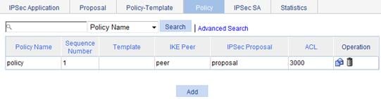
1. From the navigation tree, select VPN > IPSec.
2. Click the Policy tab.
The IPsec policy list page appears.
The Add IPSec Policy page appears.
Figure 38 Adding an IPsec policy

4. Configure an IPsec policy, as described in Table 8.
5. Click Apply.
|
Item |
Description |
|
|
Policy Name |
Enter a name for the IPsec policy. |
|
|
Sequence Number |
Enter a sequence number for the IPsec policy. In an IPsec policy group, an IPsec policy with a smaller sequence number has a higher priority. |
|
|
Template |
Select an IPsec policy template.
If you select an IPsec policy template, all subsequent configuration items except the aggregation setting are unavailable. |
|
|
IKE Peer |
Select an IKE peer for the IPsec policy. You configure IKE peers by selecting VPN > IKE from the navigation tree. |
|
|
IPSec Proposal |
Select up to six IPsec proposals for the IPsec policy. IPsec SAs can be set up only when the IPsec peers have at least one matching IPsec proposal. If no matching IPsec proposal is available, the IPsec SAs cannot be established and the packets that need to be protected are discarded. |
|
|
PFS |
Enable and configure the PFS feature or disable the feature. Options include: · dh-group1—Uses the 768-bit Diffie-Hellman group. · dh-group2—Uses the 1024-bit Diffie-Hellman group. · dh-group5—Uses the 1536-bit Diffie-Hellman group. · dh-group14—Uses the 2048-bit Diffie-Hellman group.
· dh-group14, dh-group5, dh-group2, and dh-group1 are in descending order of security and calculation time. · When IPsec uses an IPsec policy configured with PFS to initiate negotiation, an additional key exchange is performed in phase 2 for higher security. · Two peers must use the same Diffie-Hellman. Otherwise, negotiation will fail. |
|
|
ACL |
Select an ACL for identifying protected traffic. Make sure that this ACL has been created and contains at least one rule. You can use an ACL to identify traffic between VPN instances. |
|
|
Aggregation |
Select this option if you are using one tunnel to protect all data flows permitted by the ACL. If you do not select the aggregation mode, the standard mode applies and one tunnel is set up for each data flow permitted by the ACL. This configuration item is available after you specify an ACL.
The two ends of a tunnel must operate in the same mode. |
|
|
SA Lifetime |
Time Based |
Enter the time-based and traffic-based SA lifetime values.
When negotiating IPsec SAs, IKE uses the smaller one between the lifetime set locally and the lifetime proposed by the peer. |
|
Traffic Based |
||
|
Reverse Route Injection |
Enable or disable IPsec RRI. When enabling IPsec RRI, you can specify a next hop and change the preference of the static routes. After an outbound IPsec SA is created, IPsec RRI automatically creates a static route to the peer private network. You do not have to manually configure the static route.
· If you enable IPsec RRI and do not configure the static route, the SA negotiation must be initiated by the remote gateways. · IPsec RRI creates static routes when IPsec SAs are set up, and delete the static routes when the IPsec SAs are deleted. · To view the static routes created by IPsec RRI, select Network > IPv4 Routing from the navigation tree. |
|
|
Next Hop |
Specify a next hop for the static routes. If you do not specify any next hop, the remote tunnel endpoint's address learned during IPsec SA negotiation is used. |
|
|
Priority |
Change the preference of the static routes. Change the route preference for equal-cost multipath routing or route backup. If multiple routes to the same destination have the same preference, traffic is balanced among them. If multiple routes to the same destination have different preference values, the route with the highest preference forwards traffic and all other routes are backup routes. |
|
Applying an IPsec policy group
1. From the navigation tree, select VPN > IPSec.
The page for the IPSec Application tab appears.
Figure 39 IPsec application list

2. Click the icon for an interface.
The IPSec Application Setup page appears.
Figure 40 IPsec application configuration page

3. Select an IPsec policy for the interface.
4. Click Apply.
Viewing IPsec SAs
1. From the navigation tree, select VPN > IPSec.
2. Click the IPSec SA tab.
The IPsec SA list page appears.
Figure 41 IPsec SA list

Table 9 Field description
|
Field |
Description |
|
Source IP |
IP address of the local end of the IPsec SA. |
|
Destination IP |
IP address of the remote end of the IPsec SA. |
|
SPI |
SPI of the IPsec SA. |
|
Security Protocol |
Security protocol that the IPsec SA uses. |
|
Authentication Algorithm |
Authentication algorithm that the security protocol uses. |
|
Encryption Algorithm |
Encryption algorithm that the security protocol uses. |
Viewing packet statistics
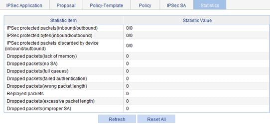
1. From the navigation tree, select VPN > IPSec.
2. Click the Statistics tab.
The packet statistics page appears.
IPsec configuration example
Network requirements
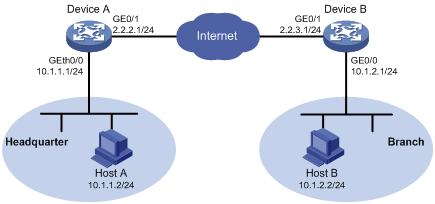
As shown in Figure 43, an enterprise branch accesses the headquarters through IPsec VPN. Configure the IPsec VPN as follows:
· Configure an IPsec tunnel between AC 1 and AC 1 to protect traffic between the headquarters subnet 10.1.1.0/24 and the branch subnet 10.1.2.0/24.
· Configure the tunnel to use the security protocol ESP, encryption algorithm DES, and authentication algorithm SHA-1.
· Enable IPsec RRI on AC 1, so AC 1 can automatically create a static route from the headquarters to the branch when the IPsec SA is established. Specify the next hop as 2.2.2.2.
Configuring AC 1
1. Configure IP addresses for the interfaces, and assign the interfaces to target zones. (Details not shown.)
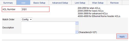
2. Define ACL 3101 to permit packets from subnet 10.1.1.0/24 to subnet 10.1.2.0/24:
a. From the navigation tree, select QoS > ACL IPv4.
b. Click the Add tab.
c. Enter the ACL number 3101, and select the match order Config.
d. Click Apply.
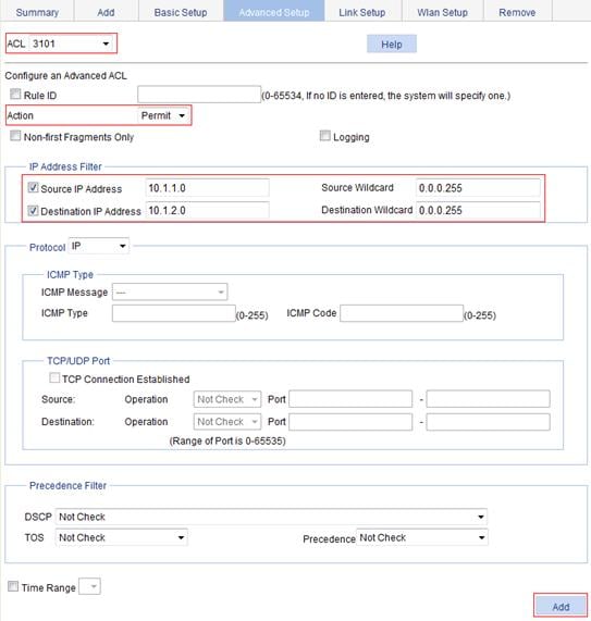
e. Click the Advanced Setup tab.
f. Select the ACL number 3101.
g. Select Permit from the Action list.
h. Select Source IP Address, and enter 10.1.1.0 and 0.0.0.255 as the source IP address and mask.
i. Select Destination IP Address, and enter 10.1.2.0 and 0.0.0.255 as the destination IP address and mask.
j. Click Apply.
Figure 45 Configuring a rule to permit packets from 10.1.1.0/24 to 10.1.2.0/24
3. Configure an IPsec proposal named tran1:
a. From the navigation tree, select VPN > IPSec.
b. Click the Proposal tab.
c. Click Add.
d. On the page that appears, select Custom mode.
e. Enter the IPsec proposal name tran1.
f. Select the packet encapsulation mode Tunnel.
g. Select the security protocol ESP.
h. Select the authentication algorithm SHA1.
i. Select the encryption algorithm DES.
j. Click Apply.
Figure 46 Configuring IPsec proposal tran1

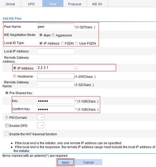
4. Configure the IKE peer:
a. From the navigation tree, select VPN > IKE.
b. Click the Peer tab.
c. Click Add.
d. Enter the peer name peer.
e. Select the negotiation mode Main.
f. Enter the remote gateway IP address 2.2.3.1.
g. Select Pre-Shared Key, and enter abcde for both the Key and Confirm Key fields.
h. Click Apply.
Figure 47 Configuring an IKE peer
5. Configure an IPsec policy:
a. From the navigation tree, select VPN > IPSec.
b. Click the Policy tab.
c. Click Add.
d. Enter the policy name map1.
e. Enter the sequence number 10.
f. Select the IKE peer peer.
g. Select the IPsec proposal tran1 and click <<.
h. Enter the ACL number 3101.
i. Select Enable for RRI.
j. Enter the next hop address 2.2.2.2.
k. Click Apply.
Figure 48 Configuring an IPsec policy

6. Apply the IPsec policy to VLAN-interface 1:
a. From the navigation tree, select VPN > IPSec.
The page for the IPSec Application tab appears.
b. Click the ![]() icon of
interface Vlan-interface 1.
icon of
interface Vlan-interface 1.
c. Select the policy of map1.
d. Click Apply.
Figure 49 Applying IPsec policy to VLAN-interface 1
Configuring Device B
The configuration steps on Device B are similar to those on Device A. The configuration pages are not shown.
1. Configure IP addresses for the interfaces, and assign the interfaces to the target zones. (Details not shown.)
2. Define an ACL to permit traffic from subnet 10.1.2.0/24 to subnet 10.1.1.0/24:
a. From the navigation tree, select QoS > ACL IPv4.
b. Click the Add tab.
c. Enter the ACL number 3101, and select the match order Config.
d. Click Apply.
e. Click the Advanced Setup tab.
f. Select the ACL number 3101.
g. Select Permit from the Action list.
h. Select Source IP Address, and enter 10.1.2.0 and 0.0.0.255 as the source IP address and mask.
i. Select Destination IP Address, and enter 10.1.1.0 and 0.0.0.255 as the destination IP address and mask.
j. Click Apply.
3. Configure a static route to Host 1:
a. From the navigation tree, select Network > IPv4 Routing.
b. Click the Add tab.
c. Enter the destination IP address 10.1.1.0 and mask 255.255.255.0.
d. Select the outbound interface Vlan-interface1.
e. Click Apply.
4. Configure an IPsec proposal named tran1:
a. From the navigation tree, select VPN > IPSec.
b. Click the Proposal tab.
c. Click Add.
d. From the IPSec Proposal Configuration Wizard page, select Custom mode.
e. Enter the IPsec proposal name tran1.
f. Select the packet encapsulation mode Tunnel.
g. Select the security protocol ESP.
h. Select the authentication algorithm SHA1.
i. Select the encryption algorithm DES.
j. Click Apply.
5. Configure IKE peer peer:
a. From the navigation tree, select VPN > IKE.
b. Click the Peer tab.
c. Click Add.
d. Enter the peer name peer.
e. Select the negotiation mode Main.
f. Enter the remote gateway IP address 2.2.2.1.
g. Select Pre-Shared Key, and enter abcde for both the Key and Confirm Key fields.
h. Click Apply.
6. Configure IPsec policy map1:
a. From the navigation tree, select VPN > IPSec.
b. Click the Policy tab.
c. Click Add.
d. Enter the policy name map1.
e. Enter the sequence number 10.
f. Select the IKE peer peer.
g. Select the IPsec proposal tran1 and click <<.
h. Enter the ACL number 3101.
i. Click Apply.
7. Apply IPsec policy map1 to VLAN-interface 1:
a. From the navigation tree, select VPN > IPSec.
The page for the IPSec Application tab appears.
b. Click the ![]() icon of
interface Vlan-interface 1.
icon of
interface Vlan-interface 1.
c. Select the policy of map1.
d. Click Apply.
Verifying the configuration
After you complete the configuration, packets to be exchanged between subnet 10.1.1.0/24 and subnet 10.1.2.0/24 triggers the negotiation of SAs by IKE. After IKE negotiation succeeds and the IPsec SAs are established, a static route to subnet 10.1.2.0/24 through 2.2.2.2 is added to the routing table on AC 1, and traffic between subnet 10.1.1.0/24 and subnet 10.1.2.0/24 is protected by IPsec.