- Table of Contents
-
- H3C Access Controllers Web-Based Configuration Guide(E3703P61 R2509P61 R3709P61 R2609P61 R3509P61)-6W103
- 00-Preface
- 01-About
- 02-Web overview
- 03-Login
- 04-Quick Start
- 05-Summary
- 06-Device
- 07-Network
- 08-AP Configuration
- 09-Wireless Service
- 10-WLAN Roaming Configuration
- 11-Radio Configuration
- 12-Authentication
- 13-Security
- 14-QoS Configuration
- 15-Advanced Settings
- 16-Stateful Failover Configuration
- 17-VPN
- 18-SSL VPN Configuration
- Related Documents
-
| Title | Size | Download |
|---|---|---|
| 08-AP Configuration | 927.97 KB |
Configuring auto-AP authentication
Converting auto APs to configured APs
Configuring IP address match criteria for an AP group
Configuring AP-based client access control
Auto-AP authentication configuration example
Configuring APs
AC-AP tunnel
As shown in Figure 1, an AC and an AP establish a data tunnel to forward data packets and a control tunnel to forward control packets used for AP configuration and management. The AC can automatically configure and manage APs based on the information provided by the administrator.

Auto AP
The auto AP feature enables an AC to automatically associate with APs. It can greatly reduce your workload when you deploy a wireless network with many APs.
You can enable auto AP in the following ways:
· Specify an auto-AP template and enable the auto-AP function.
After you create an auto-AP template on the AP > AP Setup page and enable the auto-AP function, the AC automatically associates with the APs of the model specified in the template, names the APs by using their MAC addresses, and assigns configurations in the template to APs. Clients can associate with auto APs but the administrator cannot change the configuration of auto APs.
· Enable the auto-AP function.
After you enable the auto-AP function, the AC automatically associates with all APs and names the APs by using their MAC addresses. Clients can associate with the auto APs but the administrator cannot change the configuration of the auto APs.
AP group
Overview
AP group enables you to configure multiple APs at a time, which reduces your workload.
If you do not create any AP groups, the system takes the AP group named default group as the default AP group. You can modify but not delete the default AP group. All APs created belong to the default AP group by default.
You can add APs with the same configurations or in the same subnet to the same AP group. The APs use the configuration of the AP group. If you add an auto AP template into a non-default AP group, the auto APs getting online through the template belong to the group. The auto APs use the configuration of the AP group to which the auto AP template belongs.
When you delete an AP from an AP group (equal to adding the AP to the default AP group) or add an AP to an AP group, the AP restarts, and clears its configuration except the serial number. After the AP is added to the new AP group, the AP uses the configuration of the new AP group.
The following operations might fail on some member APs:
· Select 5 GHz wireless services.
· Select 2.4 GHz wireless services.
· Enable a 5 GHz radio.
· Enable a 2.4 GHz radio.
· Set a working mode.
· Set a country/region code.
Client access control
Some wireless service providers need to control the access positions of clients. For example, as shown in Figure 2, to meet security or billing needs, it is required to connect wireless clients 1 and 2 to the wired network through AP 1 or AP 2, and connect client 3 through AP 3. To achieve this, you can configure the AP groups that the clients can be associated with and then apply the AP groups in a user profile. For more information about user profile, see "Configuring users."
Figure 2 Client access control

Configuring an AP
Creating an AP
1. Select AP > AP Setup from the navigation tree.
2. Click Add.

3. Create the AP as described in Table 1.
4. Click Apply.
|
Item |
Description |
|
AP Name |
Set the AP name. |
|
Model |
AP model. |
|
Serial ID |
Specify the serial ID: · Auto—Use the auto serial ID function together with the auto AP function. For more information about configuring auto AP, see "Configuring auto AP." · Manual—Enter an AP serial ID. By default, Auto is used. |
Setting AP parameters
1. Select AP > AP Setup from the navigation tree.
2. Click the ![]() icon for the target
AP.
icon for the target
AP.

3. Configure the AP as described in Table 2.
4. Click Apply.
|
Item |
Description |
|
AP Name |
Rename the AP. |
|
Country/Region Code |
Select a country/region code. By default, no country/region code is configured for an AP, and the global country/region code applies. If both country/region code and global country/region code are configured, the AP uses its own country/region code. For how to configure the global country/region code, see "Configuring advanced settings."
Some ACs and APs have fixed country/region codes, whichever is used is determined as follows: · An AC's fixed country/region code cannot be changed, and all managed APs whose country/region codes are not fixed must use the AC's fixed country/region code. · An AP's fixed country/region code cannot be changed and the AP can only use the country/region code. If an AC and a managed AP use different fixed country/region codes, the AP uses its own fixed country/region code. |
|
Radio Number |
Select the number of the radios on the AP. The value depends on the AP model. |
|
Radio Type |
Select the radio type, which can be one of the following values: · 802.11a. · 802.11b. · 802.11g. · 802.11n (2.4 GHz). · 802.11n (5 GHz). The value depends on the AP model and radio type. |
|
Serial ID |
Specify the serial ID: · Auto—Use the auto serial ID function together with the auto AP function. For how to configure auto AP, see "Configuring auto AP." · Manual—Enter an AP serial ID.
A serial ID uniquely identifies an AP. If the AP has connected to the AC, changing or deleting its serial ID renders the tunnel down and the AP needs to discover the AC to connect again. |
|
Description |
Description for the AP. |
Configuring advanced settings
1. Select AP > AP Setup from the navigation tree.
2. Click the ![]() icon for the target AP.
icon for the target AP.
3. On the page that appears, expand Advanced Setup.
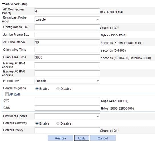
4. Configure advanced settings for the AP as described in Table 3.
5. Click Apply.
|
Item |
Description |
|
|
AP Connection Priority |
AP connection priority. Specify the AP connection priority on the AC. A greater value represents a high priority. This option needs to be used together with the AC backup function. For more information about AC backup, see "Configuring advanced settings." |
|
|
Broadcast Probe reply |
· Enable—Enable the AP to respond to broadcast probe requests. The AP will respond to broadcast probe requests with the SSID null. · Disable—Disable the AP from responding to broadcast probe requests. The AP will respond to broadcast probe requests with the specified SSID. By default, this option is enabled. |
|
|
Configuration File |
Specify a name for the configuration file (the file must exist in the storage medium of the AC) and map the specified configuration file to the AP. The configuration file takes effect when the tunnel is in Run state. When the configuration file takes effect, the AP uses the commands in the configuration file, but does not save the configuration. When local forwarding is enabled, you can use the configuration file to configure the AP. For example, when you configure a user profile when local forwarding is enabled, you must write the user profile, QoS policy, and ACL commands to the configuration file, and download the configuration file to the AP. For more information about local forwarding, see "Configuring access service."
The commands in the configuration file must be in their complete form. |
|
|
Jumbo Frame Size |
Allow the AP to send jumbo frames to the AC and set the maximum size of jumbo frames. When this function is enabled, the AP can send frames whose size does not exceed the maximum size to the AC. If this field is not specified, the AP cannot send jumbo frames to the AC. By default, the AP cannot send jumbo frames to the AC. |
|
|
AP Echo Interval |
Set the interval for sending echo requests. There is a keep-live mechanism between AP and AC, to confirm whether or not the tunnel is working. An AP periodically sends echo requests to an AC. The AC responds to echo requests by sending echo responses. If the AC does not receive any echo requests within three echo intervals, or the AP does not receive any echo responses within three echo intervals, the AC or AP terminates the tunnel. |
|
|
Client Alive Time |
Set the client keep alive interval. The keep-alive mechanism is used to detect clients segregated from the system due to reasons such as power failure or crash, and disconnect them from the AP. By default, the client keep-alive function is disabled. H3C recommends that you enable the client keep-alive function for the AP because information about clients that do not exist occupies AC memory and decreases AC performance. |
|
|
Client Free Time |
Maximum interval for which the link between the AP and a client can be idle. A connection that remains idle for the specified period of time is removed. |
|
|
Backup AC IPv4 Address |
Set the IPv4 address of the backup AC for the AP. |
· You can set both the IPv4 and IPv6 addresses of the backup AC for the AP. · If you configure the global backup AC information both in Advanced > AC Backup and AP > AP Setup, the configuration in AP > AP Setup takes precedence. For more information about AC backup, see "Configuring advanced settings." |
|
Backup AC IPv6 Address |
Set the IPv6 address of the backup AC for the AP. |
|
|
Remote AP |
Remote AP provides a wireless solution for remote branches and offices. It enables you to configure and control remote APs from the headquarters over the Internet without deploying an AC in each office or branch. As shown in the figure below, the AC manages the remote APs over the Internet. The AP automatically enables local forwarding (whether or not local forwarding is configured on the AC) to provide wireless access for logged-in clients when the tunnel between the AP and AC is terminated. However, it does not allow new clients. When a tunnel is established between the AP and AC again, the AP automatically switches to centralized forwarding mode and logs off all clients on the remote AP.
· Enable—Enable the remote AP function. · Disable—Disable the remote AP function. By default, the remote AP function is disabled.
· If an AP establishes tunnels with both the primary AC and a backup AC, it uses the backup tunnel to provide wireless access for logged-in clients when the primary tunnel fails. For more information about AC backup, see "Configuring advanced settings." · The remote AP and mesh functions cannot be used simultaneously. |
|
|
Band Navigation |
· Enable—Enable band navigation. · Disable—Disable band navigation. By default, band navigation is disabled. |
|
|
AP CAR |
Enable CAR for the AP to avoid frequent reboots caused by excessive traffic. Select this box to configure the CIR and CBS for the AP. By default, CAR is not enabled for an AP. |
|
|
CIR |
Committed information rate, in kbps. |
|
|
CBS |
Committed burst size, in bytes. When AP CAR is enabled, the CBS is the number of bytes transmitted in 500 ms at the rate of CIR. For example, if the CIR is 100, the CBS is 50000 bytes by default. |
|
|
Firmware Update |
Configure the AP firmware update function. You can configure the AP firmware update function on the Advanced > AP, AP > AP Group, or AP > AP Setup page. You can update specified APs by configuring AP firmware update functions on different pages. For more information, see "Configuring advanced settings." |
|
|
Bonjour Gateway |
· Enable—Enable Bonjour gateway for the AP. · Disable—Disable Bonjour gateway for the AP. By default, Bonjour gateway is enabled for the AP. Bonjour gateway takes effect only after you enable it both globally and for an AP. You can enable Bonjour gateway for the AP on the AP > AP Setup or AP > AP Group page, and enable Bonjour gateway globally on the Advanced Setup > Bonjour Gateway page. |
|
|
Bonjour Policy |
Apply the specified Bonjour policy. For more information, see "Configuring advanced settings." |
|

Configuring auto AP
You can enable an AP to connect to an AC by configuring the serial ID of the AP, specifying an auto-AP template, or enabling the auto AP function. The priorities of these configurations are in descending order. For example, if you configure the serial ID of an AP and enable the auto AP function, the AP gets online as a configured AP.
Enabling auto AP
You can enable auto AP in the following ways:
· Specify an auto-AP template and enable the auto-AP function.
a. On the page for adding an AP, select the AP model and select Auto from the Serial ID list.
Do not use the MAC address of an AP as the AP name because the AC names auto APs by using their MAC addresses.
b. Enable the auto AP function.
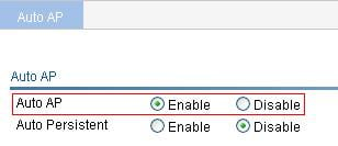
· Enable the auto-AP function.
a. Select AP > Auto AP from the navigation tree.
Figure 6 Configuring auto AP

b. Enable auto AP as described in Table 4.
c. Click Apply.
|
Item |
Description |
|
Auto AP |
· Enable—Enable the auto AP function. You must also select Auto from the Serial ID list on the AP setup page to use the auto AP function. · Disable—Disable the auto AP function. By default, the auto AP function is disabled.
For network security, disable the auto-AP function when all APs have connected to the AC. |
Clients can associate with the auto APs, but you cannot change the configuration of an auto AP.
Configuring auto-AP authentication
The auto-AP authentication function enables you to control and manage auto APs. It only takes effect for auto APs. APs in this section refer to auto APs.
Configuring auto-AP authentication
Auto-AP authentication has two modes:
· Local auto-AP authentication
In local authentication mode, the AC directly authenticates APs by serial ID or by MAC address, and uses the ACL option to specify the ACL rules for authenticating auto APs.
Assume you adopt local authentication by serial ID. When an auto AP connects to the AC, the AC uses the serial ID of the AP to match ACL rules. If the serial ID matches a permit rule, the auto AP passes the authentication and connects to the AC. If the serial ID matches a deny rule, the auto AP fails the authentication and cannot connect to the AC. If the serial ID does not match any rule, the AP is an unauthenticated AP. The ACL can be manually configured or imported from a file.
· Remote auto-AP authentication
In remote authentication mode, the AC contacts a remote authentication server to authenticate auto APs. The AC uses the serial ID or MAC address of an auto AP as the username and password and sends them to the authentication server. If the remote authentication succeeds, the AC accepts the AP. If not, the AC denies the AP.
The "unauthenticated AP" status is only available for local authentication. For remote authentication, the authentication result can only be "authentication failed" or "authentication succeeded."
To configure auto-AP authentication:
1. Select AP > Auto AP from the navigation tree.
Figure 7 Configuring auto-AP authentication
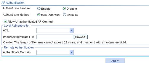
2. Configure auto-AP authentication as described in Table 5.
3. Click Apply.
|
Item |
Description |
|
|
AP Authentication |
· Enable—Enable the auto-AP authentication function. · Disable—Disable the auto-AP authentication function. By default, auto APs are not authenticated.
· Auto-AP authentication only takes effect on auto APs. · Auto-AP authentication does not take effect on online auto APs. |
|
|
Authenticate Method |
· MAC Address—The AC authenticates APs by MAC address. · Serial ID—The AC authenticates APs by serial ID. By default, the AC authenticates APs by MAC address. |
|
|
Allow Unauthenticated AP Connect |
· If you select this option, the AC accepts unauthenticated auto APs, but the auto APs cannot provide WLAN services. · If you do not select this option, the AC denies unauthenticated auto APs. By default, the AC accepts unauthenticated auto APs, but the auto APs cannot provide WLAN services. |
|
|
Local Authentication |
ACL |
Select an ACL number from the list for auto-AP authentication. Before you select an ACL number, create ACL rules on the QoS > ACL IPv4 page. For more information about ACL, see "Configuring QoS." |
|
Import Authenticate File |
Import a file for auto-AP authentication, and the system then generates corresponding ACL rules. · In the file, the MAC addresses must be in the format of HH-HH-HH-HH-HH-HH, separated by commas. The serial IDs must be in the format of serial-id1, serial-id2, serial-id3, separated by commas. · Before you execute this command, use the wlan ap-authentication acl command to specify an ACL number. The ACL rules generated will be added to the specified ACL. · When generating ACL rules, the system automatically assigns a rule ID. This rule ID is the nearest higher multiple of the numbering step to the current highest rule ID, starting from 0. For example, if the rule numbering step is 5 and the current highest rule ID is 28, the rule is numbered 30. The value range for a WLAN-AP ACL rule number is 0 to 65534. A number exceeding 65534 causes error and operation failure. · The file must have an extension of .txt. |
|
|
Remote Authentication |
Authenticate Domain |
Specify an authentication domain for auto-AP authentication. |
To re-authenticate an online auto AP, click Reset on the page shown in Figure 9 to log off the auto AP.
Enabling unauthenticated auto APs to pass authentication and provide WLAN services
Whether an unauthenticated AP can connect to the AC is determined by the Allow Unauthenticated AP Connect option. If you select this option, you can click Accept to enable the unauthenticated AP to pass authentication and provide WLAN services, or click Reject to disable the unauthenticated AP from passing authentication and providing WLAN services.
Figure 8 Enabling unauthenticated auto APs to pass authentication and provide WLAN services
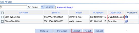
· Click Accept to change the status of an auto AP to Permitted and add the MAC address or serial ID of the auto AP to the specified ACL number. The system generates a permit rule.
· Click Reject to deny the access of an unauthenticated auto AP and add the MAC address or serial ID of the auto AP to the specified ACL number. The system generates a deny rule.
You can only perform the Accept or Reject operation on unauthenticated auto APs.
Displaying auto AP status
Click Refresh and you can view the auto AP status on the page shown in Figure 9. This page displays only unauthenticated and permitted auto APs.

Converting auto APs to configured APs
You can convert unauthenticated and authenticated auto APs to configured APs through the following ways. Configured APs are the same as APs that go online by serial ID and you can modify the parameters of the APs on the AP > AP Setup page.
Renaming an AP
1. To modify the auto AP name, click the ![]() icon in the Operation column.
icon in the Operation column.
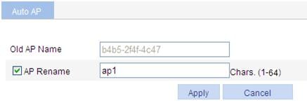
2. Select AP Rename, and enter a new AP name.
3. Click Apply.
Converting an auto AP to a configured AP
The configured APs are named by their MAC addresses.
To convert an auto AP to a configured AP:
1. Select the boxes for the target auto APs when auto APs appear on the Web interface of the AC.
2. Click Persistent.
Figure 11 Converting an auto AP to a configured AP

Enabling converting auto APs to configured APs
1. Select AP > Auto AP from the navigation tree.
2. Click Enable to the right of Auto Persistent.
3. Click Apply.
Figure 12 Enabling converting auto APs to configured APs

Table 6 Configuration items
|
Item |
Description |
|
Auto Persistent |
· Enable—Enable the function. · Disable—Disable the function. By default, this function is disabled. This option takes effect only for auto APs that go online. To convert APs that have been online to configured APs, you can only use the previous two methods. |
Configuring an AP group
Support for this feature and the number of AP groups depends on the device model. For more information, see "About the H3C Access Controllers Web-Based Configuration Guide."
Creating an AP group
1. Select AP > AP Group from the navigation tree.
2. Click Add.
Figure 13 Creating an AP group

3. Enter an AP group name, which cannot be a, al, or all.
4. Click Apply.
Configuring IP address match criteria for an AP group
Perform this task to manage APs by matching IP addresses.
Configuration guidelines
· The IP address match criteria take effect when an AP requests to associate with the AC. Any change of the criteria does not affect associated APs.
· An AP that associates with the AC by matching IP address does not support VRRP even if it disassociates and then associates with the AC again. To enable the AP to support VRRP, manually add it to another AP group where the members are not in the same subnet as the AP.
· An AP (configured or auto) that has been manually added to an AP group is always in the group even if its IP address matches the subnet of another AP group.
· For an auto AP that is already in the default group default_group, if its IP address matches the subnet of a non-default AP group, the AC adds it to this AP group.
Configuration procedure
1. Select AP > AP Group from the navigation tree.
2. Click the ![]() icon for the target AP group.
icon for the target AP group.
Figure 14 Configuring the IP address match criteria for an AP group

3. Configure the IP address match criteria as described in Table 7.
4. Click Apply.
|
Item |
Description |
|
IPv4 Address /Mask Length |
When an AP requests to associate with the AC, the AC matches the IP address of the AP against the subnets of the AP groups. If its IP address matches the subnet of a group, the AP is added to the group.
The IP address ranges of different AP groups cannot overlap. |
|
IPv6 Address/Prefix Length |
Adding an AP to an AP group
1. Select AP > AP Group from the navigation tree.
2. Click the ![]() icon for the target AP group.
icon for the target AP group.
Figure 15 Adding an AP into an AP group
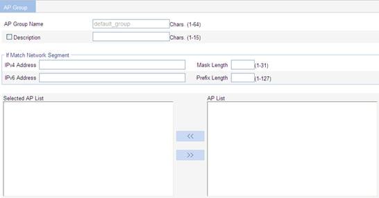
3. Configure the AP group as described in Table 8.
4. Click Apply.
|
Item |
Description |
|
AP Group Name |
Display the name of the selected AP group. |
|
Description |
Select this option to configure a description for the AP group. |
|
Selected AP List |
Add an AP to an AP group. · To add the APs to the Selected AP List, click the APs to be added to the AP group, and click the << button in the AP List area. · To delete the selected APs from the AP group, select the APs to be deleted in the Selected AP List, and click the >> button. Create the APs to be added in AP List by selecting AP > AP Setup first.
· When you delete an AP from an AP group (equal to adding the AP to the default AP group) or add an AP to an AP group, the AP clears its configuration except the serial number. After the AP is added to the new AP group, the AP uses the configuration of the new AP group. · By default, an auto AP connected to the AC by the auto AP function belongs to the same AP group with the AP template. An auto AP cannot be added into other AP groups before being converted to configured AP. |
Configuring an AP group
You can configure an AP on the AP > AP Setup page, or configure multiple APs on the AP > AP Group page. New configurations override the existing ones.
The following operations might fail on some member APs:
· Select 5 GHz wireless services.
· Select 2.4 GHz wireless services.
· Enable a 5 GHz radio.
· Enable a 2.4 GHz radio.
· Set a working mode.
· Set a country/region code
Configuring basic settings
1. Select AP > AP Group from the navigation tree.
2. Click the ![]() icon for the target AP group.
icon for the target AP group.
Figure 16 Configuring basic settings

3. Configure the AP group as described in Table 9.
4. Click Apply.
|
Item |
Description |
|
AP Group Name |
Name of the specified AP group. |
|
Description |
Select this option to configure a description for the AP group. |
|
Bind a wireless service to the 5 GHz radio. You can bind a wireless service to the radio of the AP on the AP > AP Group page and then on the Wireless Service > Access Service page. However, the total number of wireless services bound to the radio on the two pages cannot exceed the maximum number of wireless services allowed by the radio. |
|
|
Selected 2.4GHz Wireless Service List |
Bind a wireless service to the 2.4 GHz radio. You can bind a wireless service to the radio of the AP on the AP > AP Group page and then on the Wireless Service > Access Service page. However, the total number of wireless services bound to the radio on the two pages cannot exceed the maximum number of wireless services allowed by the radio. |
|
· Enable—Enable the 5 GHz radio. · Disable—Disable the 5 GHz radio. By default, the 5 GHz radio is disabled. An AP examines the configuration before it uses the configuration of the AP group to which it belongs. An AP might fail to implement the configuration due to configuration conflicts such as a disconnected uplink with uplink detection enabled. |
|
|
2.4GHz Radio |
· Enable—Enable the 2.4 GHz radio. · Disable—Disable the 2.4 GHz radio. By default, the 2.4 GHz radio is disabled. An AP examines the configuration before inheritance. An AP might fail to implement the configuration because of configuration conflicts such as a disconnected uplink with uplink detection enabled. |
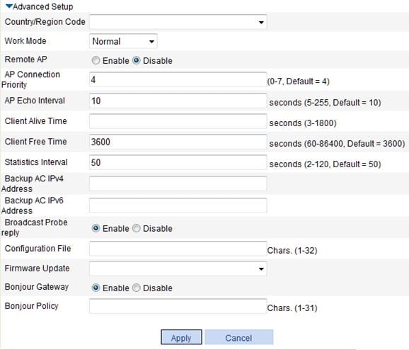
Configuring advanced settings
Figure 17 Configuring advanced settings
|
Item |
Description |
|
For more information about the configurations of items not listed in the table, see Table 2 and Table 3. A member AP uses the country/region code of the AP group even if the AP does not support the code. In such cases, the AP uses the global country/region code. |
|
|
Work Mode |
Configure the work mode. · Normal—An AP operating in normal mode transmits but does not monitor user data. · Monitor—The AP operates as a monitoring AP but not access AP. An AP in monitor mode disables all WLAN services, and monitors all 802.11 frames. · Hybrid—An AP in hybrid mode transmits and monitors user data.
Support for the number of APs supporting the monitor mode varies with device models. The number of APs operating in monitor mode cannot exceed the upper limit for the AC. For example, if an AC supports 32 APs to operate in monitor mode and there has existed 30 APs in the monitor mode, only the first two APs in an AP group can be configured to operate in the monitor mode. |
|
Statistics Interval |
Configure the interval at which an AP sends statistics reports. The statistics report covers radio decryption error, radio statistics, and so on. |
|
Firmware Update |
Configure the AP firmware update function. You can configure the AP firmware update function on the Advanced > AP, AP > AP Group, or AP > AP Setup page. You can update specified APs by configuring AP firmware update functions on different pages. For more information, see "Configuring advanced settings." |
Configuring a venue
Figure 18 Configuring a venue
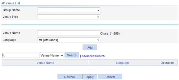
Table 11 Configuration items
|
Item |
Description |
|
Group Name |
Specify the group name for the venue in Hotspot 2.0. |
|
Venue Type |
Specify the venue type in Hotspot 2.0. |
|
Venue Name |
Specify the venue name. |
|
Language |
Specify the language code. |
Configuring AP-based client access control
To configure client access control, you need to create an AP group and add APs into the group.
Configuring a user profile
1. Select Authentication > Users from the navigation tree.
2. Click User Profile.
3. Click Add.
Figure 19 Setting the user profile name
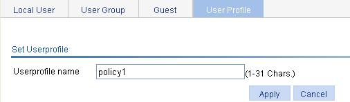
4. Specify a name for the user profile.
5. Click Apply.
The user profile configuration page appears.
Figure 20 Configuring a user profile

6. Configure the user profile as described in Table 12.
7. Click Apply.
For more information about user profile, see "Configuring users."
|
Item |
Description |
|
AP Group list permitted |
Specify the AP groups permitted in the user profile. Select the AP groups in the AP group list and click the << button to add them to the Selected AP group list. The available AP groups are AP groups you configured on the page you enter by selecting AP > AP Group. For more information, see "Configuring an AP group". |
8. On the user profile management page, select the user profile to be enabled.
9. Click Enable.
AP configuration examples
Auto AP configuration example
Network requirement
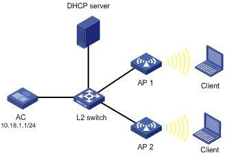
To simplify AP configuration, configure the auto AP function to enable the AP with the model WA2220X-AG to automatically connect to the AC. Configure the AP to obtain an IP address through a DHCP server and to provide clear-type wireless service with the SSID service1.
Configuring the AC
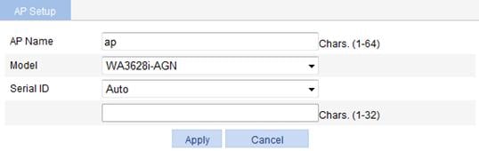
1. Create an AP:
a. Select AP > AP Setup from the navigation tree.
b. Click Add.
c. On the page that appears, set the AP name to ap, select the AP model WA3628i-AGN, select the serial ID auto, and click Apply.
2. Configure wireless service:
a. Select Wireless Service > Access Service from the navigation tree.
b. Click Add.
c. On the page that appears, set the service name to service1, select the wireless service type Clear, and click Apply.
Figure 23 Creating a wireless service

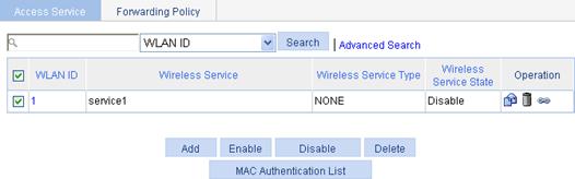
3. Enable the wireless service:
a. Select Wireless Service > Access Service from the navigation tree.
b. Select the service1 box.
c. Click Enable.
Figure 24 Enabling the wireless service
4. Bind an AP to a wireless service:
a. Select Wireless Service > Access Service from the navigation tree.
b. Click the ![]() icon for the
wireless service service1 to enter the page for
binding an AP.
icon for the
wireless service service1 to enter the page for
binding an AP.
c. Select the box to the left of the target AP.
d. Click Bind.

e. Select AP > AP Setup from the navigation tree. You can see that the AP is in IDLE state.
Figure 26 AP status before auto AP is enabled

5. Enable 802.11gn radio:
a. Select Radio > Radio Setup from the navigation tree.
b. Select the box to the left of the target AP.
c. Click Enable.
Figure 27 Enabling 802.11gn radio

6. Enable auto AP:
a. Select AP > Auto AP from the navigation tree.
b. Select Enable from the Auto AP list.
c. Click Apply.
d. After enabling auto AP, click Refresh to view the auto AP.
Figure 29 Viewing the auto AP

Verifying the configuration
· Select AP > AP Setup from the navigation tree.
You can see that the AP is in run state.
· The client can successfully associate with the AP and access the WLAN network.
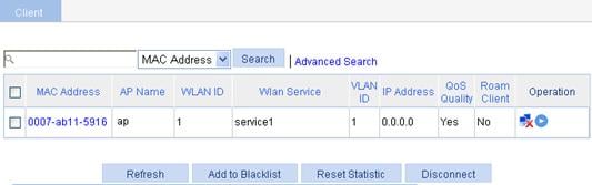
· You can view the online clients on the page you enter by selecting Summary > Client from the navigation tree.
Figure 30 Viewing the online clients
Auto-AP authentication configuration example
Network requirements
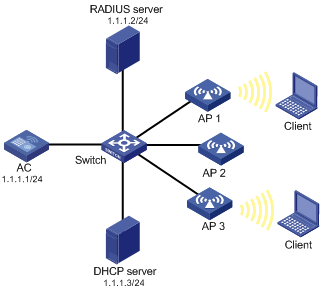
As shown in Figure 31, enable the auto-AP function, and configure auto-AP authentication on the AC to permit AP 1 and deny AP 2. Use the DHCP server to assign IP addresses to authenticated APs. Use the RADIUS server to authenticate the unauthenticated AP (AP 3 in this example).
The serial IDs of AP 1, AP 2, and AP 3 are 210235A42QB095000761, 210235A42QB095000762, and 210235A42QB095000763, respectively.
Configuring the AC
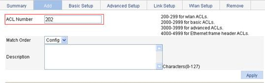
1. Create ACL 202:
a. Select QoS > ACL IPv4 from the navigation tree.
b. Click Add.
c. Type ACL ID 202.
d. Click Apply.
Figure 32 Creating ACL 202
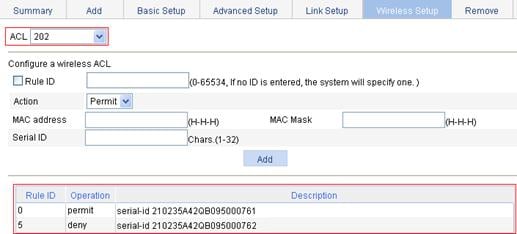
2. Configure a permit rule to allow AP 1 with the serial ID 210235A42QB095000761 and a deny rule to deny AP 2 with the serial ID 210235A42QB095000762.
a. Select QoS > ACL IPv4 from the navigation tree.
b. Click the Wireless Setup tab.
c. Select 202 from the ACL list and add two ACL rules as shown in Figure 33.
d. Click Apply.
Figure 33 Configuring ACL rules
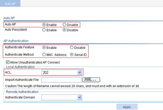
3. Configure the auto AP function:
a. Select AP > Auto AP from the navigation tree.
b. Select Enable for Auto AP.
c. Select Enable for Authenticate Feature, and Serial ID for Authenticate Method.
d. Select 202 from the ACL list.
e. Click Apply.
Figure 34 Configuring auto AP
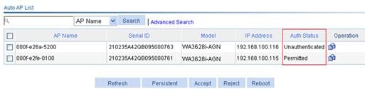
4. Display the auto AP status:
To display auto AP status, click Refresh.
Figure 35 Displaying auto AP status
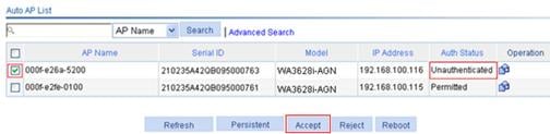
5. Enable the unauthenticated auto AP to pass authentication and provide WLAN services:
a. Select the box to the left of the target AP.
b. Click Accept.
Figure 36 Enabling the unauthenticated auto AP to pass authentication and provide WLAN services
Verifying the configuration
· AP 1 matches the permit rule, so it can connect to the AC.
· AP 2 matches the deny rule, so it cannot connect to the AC.
· AP 3 does not match any rule, so it is authenticated by the remote RADIUS server. If it passes the authentication, it can connect to the AC to provide WLAN services.