- Table of Contents
-
- H3C S5500-SI Series Ethernet Switches Operation Manual-Release 1205-(V1.03)
- 00-1Cover
- 00-2Overview
- 01-Login Operation
- 02-Basic System Configuration and Maintenance Operation
- 03-File System Management Operation
- 04-VLAN Operation
- 05-QinQ-BPDU TUNNEL Operation
- 06-Port Correlation Configuration Operation
- 07-MAC Address Table Management Operation
- 08-MSTP Operation
- 09-IP Address and Performance Operation
- 10-IPv6 Configuration Operation
- 11-Routing Overview Operation
- 12-IPV4 Routing Operation
- 13-IPv6 Routing Operation
- 14-802.1x-HABP-MAC Authentication Operation
- 15-AAA-RADIUS-HWTACACS Operation
- 16-Multicast Protocol Operation
- 17-ARP Operation
- 18-DHCP Operation
- 19-ACL Operation
- 20-QoS Operation
- 21-Port Mirroring Operation
- 22-Cluster Operation
- 23-SNMP-RMON Operation
- 24-NTP Operation
- 25-DNS Operation
- 26-Information Center Operation
- 27-NQA Operation
- 28-SSH Terminal Service Operation
- 29-UDP Helper Operation
- 30-SSL-HTTPS Operation
- 31-PKI Operation
- 32-PoE-PoE Profile Operation
- 33-Appendix
- Related Documents
-
| Title | Size | Download |
|---|---|---|
| 32-PoE-PoE Profile Operation | 270 KB |
Table of Contents
1.3 Configuring the PoE Interface
1.3.1 Configuring a PoE Interface through the Command Line
1.3.2 Configuring PoE Interfaces through a PoE Configuration File
1.4 Configuring PD Power Management
1.5 Configuring a Power Alarm Threshold for the PSE
1.6 Upgrading PSE Processing Software Online
1.7 Configuring a PD Disconnection Detection Mode
1.8 Enabling the PSE to Detect Nonstandard PDs
1.9 Displaying and Maintaining PoE
1.10 PoE Configuration Example
Chapter 1 PoE Configuration
1.1 PoE Overview
1.1.1 Introduction to PoE
Power over Ethernet (PoE) means that power sourcing equipment (PSE) supplies power to powered devices (PD) such as IP telephone, wireless LAN access point, and web camera from Ethernet interfaces through twisted pair cables.
I. Advantages
l Reliable: Power is supplied in a centralized way so that it is very convenient to provide a backup power supply.
l Easy to connect: A network terminal requires only one Ethernet cable, but no external power supply.
l Standard: In compliance with IEEE 802.3af, a globally uniform power interface is adopted.
l Promising: It can be applied to IP telephones, wireless LAN access points, portable chargers, card readers, web cameras, and data collectors.
II. Composition
A PoE system consists of PoE power, PSE, and PD.
l PoE power
The whole PoE system is powered by the PoE power, which includes external PoE power and internal PoE power.
& Note:
The support for the PoE power type depends on the device model.
l PSE
PSE is a card or subcard. PSE manages its own PoE interfaces independently. PSE examines the Ethernet cables connected to PoE interfaces, searches for the devices that comply with the specification, classifies them, and supplies power to them. When detecting a PD is unplugged, the PSE stops supplying the power to the PD.
An Ethernet interface with the PoE capability is called PoE interface. Currently, a PoE interface can be an FE or GE interface.
l PD
A PD is a device accepting power from the PSE. There are standard PDs and nonstandard PDs. A standard PD refers to the one that complies with IEEE 802.3af. The PD that is being powered by the PSE can be connected to other power supply unit for redundancy backup.
1.1.2 Protocol Specification
The protocol specification related to PoE is IEEE 802.3af.
1.2 PoE Configuration Tasks
Complete these tasks to configure PoE:
|
Task |
Remarks |
|
Required |
|
|
Optional |
|
|
Optional |
|
|
Optional |
|
|
Optional |
|
|
Optional |
1.3 Configuring the PoE Interface
You can configure a PoE interface in either of the following two ways:
l Adopt the command line.
l Configure a PoE configuration file and apply the file to the specified PoE interface(s).
Usually, you can adopt the command line to configure a single PoE interface, and adopt a PoE configuration file to batch configure PoE interfaces.
![]() Caution:
Caution:
You can adopt either mode to configure, modify, or delete a PoE configuration parameter under the same PoE interface.
The PSE applies power to a PoE interface in two modes. For a device with only signal cables, power is supplied over signal cables. An S5500-SI switch cannot provide power supply through spare cables. So you need to use an intermediate device for an S5500-SI switch to provide power supply to devices that can only be powered by spare cables.
To clearly identify the PD connected to a PoE interface, you can give a PD description.
1.3.1 Configuring a PoE Interface through the Command Line
Follow these steps to configure a PoE interface through the command line:
|
To do… |
Use the command… |
Remarks |
|
Enter system view |
system-view |
— |
|
Enter PoE interface view |
interface interface-type interface-number |
— |
|
Enable PoE |
poe enable |
Required By default, PoE is disabled on the PoE interface. |
|
Configure the maximum power for the PoE interface |
poe max-power max-power |
Optional By default, the maximum power on the PoE interface is 15,400 milliwatts. |
|
Configure the PoE mode for the PoE interface |
poe mode signal |
Optional By default, the PoE mode is signal (power over signal cables). |
|
Configure a description for the PD connected to the PoE interface |
poe pd-description string |
Optional |
1.3.2 Configuring PoE Interfaces through a PoE Configuration File
A PoE configuration file is used to batch configure PoE interfaces with the same attributes to simplify operations. This configuration method is a supplement to the common command line configuration.
Commands in a PoE configuration file are called configurations.
Follow these steps to configure PoE interfaces through a PoE configuration file:
|
To do… |
Use the command… |
Remarks |
|
|
Enter system view |
system-view |
— |
|
|
Create a PoE configuration file and enter PoE configuration file view |
poe-profile profile-name [ index ] |
Required |
|
|
Enable PoE for the PoE interface |
poe enable |
Required By default, PoE is disabled on a PoE interface. |
|
|
Configure the maximum power for the PoE interface |
poe max-power max-power |
Optional By default, the maximum power on the PoE interface is 15,400 milliwatts. |
|
|
Configure the PoE mode for the PoE interface |
poe mode signal |
Optional By default, the PoE mode is signal (power over signal cables). |
|
|
Return to system view |
quit |
— |
|
|
Apply the PoE configuration file to the PoE interface(s) |
Apply the PoE configuration file to one or more PoE interfaces |
apply poe-profile { index index | name profile-name } interface interface-range |
Use either approach |
|
Apply the PoE configuration file to the current PoE interface in PoE interface view |
interface interface-type interface-number |
||
|
apply poe-profile { index index | name profile-name } |
|||
![]() Caution:
Caution:
l After a PoE configuration file is applied to a PoE interface, other PoE configuration files can not take effect on this PoE interface.
l If a PoE configuration file is already applied to a PoE interface, you must execute the undo apply poe-profile command to remove the application to the interface before deleting or modifying the PoE configuration file.
l If you have configured a PoE interface through the command line, you cannot configure it through a PoE configuration file again. If you want to reconfigure the interface through a PoE configuration file, you must first remove the command line configuration on the PoE interface.
l You must use the same mode (command line or PoE configuration file) to configure the poe max-power max-power and poe priority { critical | high | low } commands.
1.4 Configuring PD Power Management
The power priority of a PD depends on the priority of the PoE interface. The priority levels of PoE interfaces include critical, high and low in descending order. Power supply to a PD is subject to PD power management policies.
all PSEs implement the same PD power management policies. When the PSE supplies power to a PD,
l By default, no power will be supplied to a new PD if the PSE power is overloaded.
l Under the control of a priority policy, the PD with a lower priority is first powered off to guarantee the power supply to the new PD with a higher priority when the PSE power is overloaded.
If the guaranteed remaining PSE power (maximum PSE power – power allocated to the critical PoE interface, regardless of whether PoE is enabled for the PoE interface) is lower than the maximum power of the PoE interface, you will fail to set the priority of the PoE interface to critical. Otherwise, you can succeed in setting the priority to critical, this PoE interface will preempt the power of other PoE interfaces with a lower priority level. In the latter case, the PoE interfaces whose power is preempted will be powered off, but their configurations will remain unchanged. When you change the priority of a PoE interface from critical to a lower level, the PDs connecting to other PoE interfaces will have an opportunity of seizing power.
I. Configuration prerequisites
Enable PoE for PoE interfaces.
II. Configuration procedure
Follow these steps to configure PD power management:
|
To do… |
Use the command… |
Remarks |
|
|
Enter system view |
system-view |
— |
|
|
Configure the power priority for a PoE interface. |
Configure the power priority for the PoE interface in PoE interface view |
interface interface-type interface-number |
Use either approach. By default, the power priority of a PoE interface is low. |
|
poe priority { critical | high | low } |
|||
|
Configure the power priority for the PoE interface in PoE configuration file view |
poe-profile profile-name [ index ] |
||
|
poe priority { critical | high | low } |
|||
|
Configure a PD power management priority policy |
poe pd-policy priority |
Optional By default, no PD power management priority policy is configured. |
|
1.5 Configuring a Power Alarm Threshold for the PSE
l When the current power utilization of the PSE is above or below the alarm threshold for the first time, the system will send a Trap message.
l When the PSE starts or stops supplying power to a PD, the system will send a Trap message, too.
Follow these steps to configure a power alarm threshold for the PSE:
|
To do… |
Use the command… |
Remarks |
|
Enter system view |
system-view |
— |
|
Configure a power alarm threshold for the PSE |
poe utilization-threshold utilization-threshold-value |
Optional By default, the power alarm threshold for the PSE is 80%. |
1.6 Upgrading PSE Processing Software Online
You can upgrade the PSE processing software online in either of the following modes:
l Refresh mode
Normally, you can upgrade the PSE processing software in the Refresh mode through the command line.
l Full mode
When an exception, such as interruption (power failure) or error, occurs during the upgrade in Refresh mode, you can upgrade the PSE processing software in Full mode.
& Note:
When the PSE processing software is damaged (in this case, you can execute none of PoE commands successfully), you can upgrade the PSE software processing software in Full mode to restore the PSE function. Online PSE processing software upgrade may be unexpectedly interrupted (for example, an error results in device reboot). If you fail to upgrade the PSE processing software in Full mode after reboot, you can power off the device and restart it before upgrading it again. After upgrade, restart the device manually to make the original PoE configurations take effect. The support for this upgrade method depends on the device model.
Follow these steps to upgrade the PSE processing software online:
|
To do… |
Use the command… |
Remarks |
|
Enter system view |
system-view |
— |
|
Upgrade the PSE processing software online |
poe update { full | refresh } filename |
Optional |
1.7 Configuring a PD Disconnection Detection Mode
Follow these steps to configure a PD disconnection detection mode:
|
To do… |
Use the command… |
Remarks |
|
Enter system view |
system-view |
— |
|
Configure a PD disconnection detection mode |
poe disconnect { ac | dc } |
Optional The default PD disconnection detection mode depends on the device model. |
![]() Caution:
Caution:
If you adjust the PD disconnection detection mode when the device is running, the connected PDs will be powered off. Therefore, be cautious to do so!
1.8 Enabling the PSE to Detect Nonstandard PDs
There are standard PDs and nonstandard PDs. Usually, the PSE can detect only standard PDs and supply power to them. The PSE can detect nonstandard PDs and supply power to them only after the PSE is enabled to detect nonstandard PDs.
Follow these steps to enable the PSE to detect nonstandard PDs:
|
To do… |
Use the command… |
Remarks |
|
Enter system view |
system-view |
— |
|
Enable the PSE to supply power to the detected nonstandard PDs |
poe legacy enable |
Optional By default, the PSE is disabled from supplying power to the detected nonstandard PDs. |
1.9 Displaying and Maintaining PoE
|
To do… |
Use the command… |
Remarks |
|
Display the mapping between ID, module, and slot of all PSEs. |
display poe device |
Available in any view |
|
Display the power state and information of the specified PoE interface |
display poe interface [ interface-type interface-number ] |
Available in any view |
|
Display the power information of a PoE interface(s) |
display poe interface power [ interface-type interface-number ] |
Available in any view |
|
Display the information of PSE |
display poe pse [ pse-id ] |
Available in any view |
|
Display the power state and information of PoE interfaces connected with the PSE |
display poe interface [ interface-type interfece-number ] |
Available in any view |
|
Display the power of all PoE interfaces connected with the PSE |
display poe interface power [ interface-type interface-number ] |
Available in any view |
|
Display all information of the configurations and applications of the PoE configuration file |
display poe-profile [ index index | name profile-name ] |
Available in any view |
|
Display all information of the configurations and applications of the PoE configuration file applied to the specified PoE interface |
display poe-profile interface interface-type interface-number |
Available in any view |
1.10 PoE Configuration Example
I. Network requirements
l GigabitEthernet1/0/1 and GigabitEthernet1/0/2 are connected to IP telephones.
l GigabitEthernet1/0/5 and GigabitEthernet1/0/6 are connected to access point (AP) devices.
l The power priority of GigabitEthernet1/0/2 is critical.
l The power of the AP device connected to GigabitEthernet1/0/5 does not exceed 9,000 milliwatts.
II. Network diagram
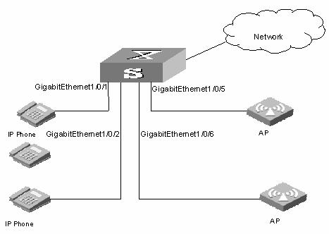
Figure 1-1 Network diagram for PoE
III. Configuration procedure
# Enable PoE on GigabitEthernet1/0/1, GigabitEthernet1/0/2, GigabitEthernet1/0/5, and GigabitEthernet1/0/6.
<Sysname> system-view
[Sysname] interface gigabitethernet 1/0/1
[Sysname-GigabitEthernet1/0/1] poe enable
[Sysname-GigabitEthernet1/0/1]quit
[Sysname] interface gigabitethernet 1/0/2
[Sysname-GigabitEthernet1/0/2] poe enable
[Sysname-GigabitEthernet1/0/2]quit
[Sysname] interface gigabitethernet 1/0/5
[Sysname-GigabitEthernet1/0/5] poe enable
[Sysname-GigabitEthernet1/0/5]quit
[Sysname] interface gigabitethernet 1/0/6
[Sysname-GigabitEthernet1/0/6] poe enable
# Set the power priority level of GigabitEthernet1/0/2 to critical.
<Sysname> sytem view
[Sysname] interface gigabitethernet 1/0/2
[Sysname-GigabitEthernet1/0/2] poe priority critical
# Set the maximum power of GigabitEthernet1/0/5 to 9,000 milliwatts.
[Sysname] interface gigabitethernet 1/0/5
[Sysname-GigabitEthernet1/0/5] poe max-power 9000
1.11 Troubleshooting PoE
Symptom: Setting the priority of a PoE interface to critical fails.
Analysis:
l The guaranteed remaining power of the PSE is lower than the maximum power of the PoE interface.
l The priority of the PoE interface is already set.
Solution:
l In the former case, you can solve the problem by increasing the maximum PSE power, or by reducing the maximum power of the PoE interface when the guaranteed remaining power of the PSE cannot be modified.
l In the latter case, you should first remove the priority already configured.
Symptom: Applying a PoE configuration file to a PoE interface fails.
Analysis:
l Some configurations in the PoE configuration file are already configured.
l Some configurations in the PoE configuration file do not meet the configuration requirements of the PoE interface.
l Another PoE configuration file is already applied to the PoE interface.
Solution:
l In case 1, you can solve the problem by removing the original configurations of those configurations.
l In case 2, you need to need to modify some configurations in the PoE configuration file.
l In case 3, you need to remove the application of the undesired PoE configuration file to the PoE interface.
Symptom: Provided that parameters are valid, configuring an AC input under-voltage threshold fails.
Analysis:
The AC input under-voltage threshold is greater than or equal to the AC input over-voltage threshold.
Solution:
You can drop the AC input under-voltage threshold below the AC input over-voltage threshold.