- Table of Contents
-
- 04-Network Connectivity Configuration Guide
- 00-Preface
- 01-About the network connectivity configuration guide
- 02-MAC address table configuration
- 03-Ethernet link aggregation configuration
- 04-Port isolation configuration
- 05-VLAN configuration
- 06-Loop detection configuration
- 07-Spanning tree configuration
- 08-LLDP configuration
- 09-Layer 2 forwarding configuration
- 10-PPP configuration
- 11-ARP configuration
- 12-IP addressing configuration
- 13-DHCP configuration
- 14-DHCPv6 configuration
- 15-DNS configuration
- 16-NAT configuration
- 17-EoGRE configuration
- 18-IP performance optimization configuration
- 19-IPv6 basics configuration
- 20-Basic IP routing configuration
- 21-Static routing configuration
- 22-IPv6 static routing configuration
- 23-Multicast overview
- 24-IGMP snooping configuration
- 25-MLD snooping configuration
- Related Documents
-
| Title | Size | Download |
|---|---|---|
| 17-EoGRE configuration | 152.39 KB |
Contents
EoGRE-in-UDP encapsulation format
EoGRE tunnel operating principle
Restrictions: Hardware compatibility with EoGRE
Restrictions and guidelines: EoGRE configuration
Configuring an IPv4 EoGRE tunnel
Display and maintenance commands for EoGRE
Example: Configuring an IPv4 EoGRE tunnel
Hosts at both ends of an EoGRE tunnel cannot ping each other
Configuring EoGRE
About EoGRE
Ethernet over GRE (EoGRE) is a tunneling protocol that can encapsulate the Ethernet protocol into a virtual point-to-point tunnel over an IP network. Ethernet frames are encapsulated at one tunnel end and de-encapsulated at the other tunnel end.
EoGRE supports EoGRE tunnel mode and EoGRE-in-UDP tunnel mode. Set the tunnel mode to EoGRE-in-UDP only if Layer 2 Ethernet packets are forwarded across a Layer 3 network with NAT traversal.
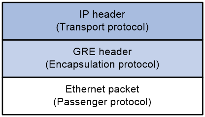
EoGRE encapsulation format
As shown in Figure 1, an EoGRE-tunneled packet includes the following parts:
· Ethernet packet—Ethernet packet to be encapsulated and transmitted.
· GRE header—Header that is added to the Ethernet packet to change the Ethernet packet to an EoGRE packet. The header includes the Protocol Type and Flags fields. GRE is called the encapsulation protocol.
· Delivery header—Header that is added to the EoGRE packet to deliver it to the tunnel end. The delivery protocol (or transport protocol) is the network layer protocol that transfers EoGRE packets.
The device supports EoGRE tunnels with IPv4 as the transport protocol. When the transport protocol is IPv4, the EoGRE tunnel mode is IPv4 EoGRE.
Figure 1 EoGRE encapsulation format
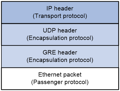
EoGRE-in-UDP encapsulation format
As shown in Figure 2, an EoGRE-tunneled packet in UDP encapsulation includes the following parts:
· Ethernet packet—Ethernet packet to be encapsulated and transmitted.
· GRE header—Header that is added to the Ethernet packet to change the Ethernet packet to an EoGRE packet. The header includes the Protocol Type and Flags fields and other extended fields. If the Flags field is set to 1, the EoGRE packet carries extended fields. If the Flags field is set to 0, the EoGRE packet does not carry extended fields. The extended fields include the Network Policy ID and AP MAC fields. The AP MAC can be the bridge MAC address or BSSID of the local device. GRE is called the encapsulation protocol.
· UDP header—Header that is added to the EoGRE packet to change the EoGRE packet to a UDP packet. The header includes the source and destination port numbers. The source port number is 4754. The destination port number by default is 4754, which is user configurable. UDP is called the encapsulation protocol.
· Delivery header—Header that is added to the UDP packet to deliver it to the tunnel end. The delivery protocol (or transport protocol) is the network layer protocol that transfers UDP packets.
The device supports UDP-encapsulated EoGRE tunnels with IPv4 as the transport protocol. When the transport protocol is IPv4, the EoGRE tunnel mode is IPv4 EoGRE-in-UDP.
Figure 2 EoGRE-in-UDP encapsulation format
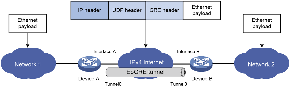
EoGRE tunnel operating principle
As shown in Figure 3 and Figure 4, an Ethernet packet traverses an IPv4 network through an EoGRE tunnel as follows:
1. After receiving an Ethernet packet from the interface connected to Network 1, Device A processes the packet as follows:
a. Looks up the MAC address table to identify that the Ethernet packet will be forwarded out of Interface A.
b. Searches for the EoGRE tunnel interface mapped to Interface A. In this example, EoGRE tunnel interface Tunnel 0 is mapped to the interface.
c. Submits the Ethernet packet to the outgoing interface, which is EoGRE tunnel interface Tunnel 0.
2. Upon receiving the packet, the EoGRE tunnel interface first encapsulates the packet with a GRE header. If the tunnel mode is EoGRE-in-UDP, the tunnel interface then encapsulates the packet with a UDP header. Finally, the tunnel interface encapsulates the packet with an IPv4 header. In the IPv4 header:
¡ The source address is the tunnel's source address (the IP address of Interface A on Device A).
¡ The destination address is the tunnel's destination address (the IP address of Interface B on Device B).
3. Device A looks up the routing table according to the destination address in the IPv4 header, and forwards the IPv4 packet out of the physical interface (Interface A) of the EoGRE tunnel.
4. When the IPv4 packet arrives at the EoGRE tunnel destination Device B, Device B checks the destination address. Because the destination is Device B itself and the protocol number in the IPv4 header is 6558 (represents that the inner packet is a Layer 2 packet), Device B submits the packet to EoGRE for de-encapsulation.
5. For EoGRE tunnel mode, EoGRE first removes the IPv4 header and GRE header, and then submits the Ethernet packet to Layer 2 forwarding for further processing. For EoGRE-in-UDP tunnel mode, EoGRE first removes the IPv4 header, UDP header, and GRE header, and then submits the Ethernet packet to Layer 2 forwarding for further processing.
Figure 3 Ethernet networks interconnected through an EoGRE tunnel
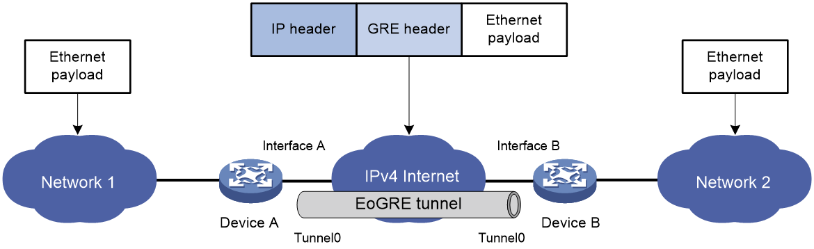
Figure 4 Ethernet networks interconnected through a UDP-encapsulated EoGRE tunnel
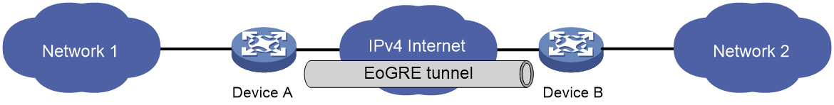
EoGRE application scenario
EoGRE applies to scenarios where two Layer 2 Ethernet networks communicate with each other over a Layer 3 network. As shown in Figure 5, Network 1 and Network 2 are Ethernet networks. Establish an EoGRE tunnel between Device A and Device B to interconnect Network 1 and Network 2. The two Ethernet networks can reach each other at Layer 2 over the Layer 3 backbone network.
Figure 5 EoGRE application scenario
Protocols and standards
· RFC 1701, Generic Routing Encapsulation (GRE)
· RFC 1702, Generic Routing Encapsulation over IPv4 networks
· RFC 2784, Generic Routing Encapsulation (GRE)
Restrictions: Hardware compatibility with EoGRE
|
Hardware series |
Model |
EoGRE compatibility |
|
WA7200 series |
WA7220 WA7220-HI WA7220H WA7226-C WA7230 WA7230-LI |
No |
|
WA7300 series |
WA7320i WA7322H-HI WA7330X WA7338-HI |
No |
|
WA7500 series |
WA7538 WA7539 |
Yes |
|
WA7600 series |
WA7638 |
No |
Restrictions and guidelines: EoGRE configuration
· EoGRE encapsulation and de-encapsulation can decrease the forwarding efficiency of tunnel-end devices.
· You must configure the tunnel source address and destination address at both ends of a tunnel. The tunnel source (or destination) address at one end must be the tunnel destination (or source) address at the other end.
· As a best practice, do not configure the same tunnel source and destination addresses for local tunnel interfaces that use the same tunnel mode.
Configuring an IPv4 EoGRE tunnel
Configuring a Layer 2 VEB interface
1. Enter system view.
system-view
2. Create a Layer 2 virtual Ethernet bridge (VEB) interface and enter its view.
interface ve-bridge number
3. Set the port link type to trunk.
port link-type trunk
4. Assign the VEB interface to a list of VLANs.
port trunk permit vlan vlan-id-list
Configuring an EoGRE tunnel
1. Enter system view.
system-view
2. Create an IPv4 EoGRE tunnel interface and enter its view.
interface tunnel number mode { eogre }
You must configure the same tunnel mode on both ends of a tunnel. Otherwise, packet delivery might fail.
3. (Optional.) Configure an IP address for the tunnel interface based on the Ethernet protocol.
For information about assigning an IPv4 address to an interface, see "Configuring IP addressing.
By default, no IP address is configured for a tunnel interface.
4. Configure a source address or source interface for the tunnel.
source { ip-address | interface-type interface-number }
By default, no source address or interface is configured for a tunnel.
If you configure a source address, the tunnel interface uses the source address as the source address of encapsulated packets.
If you configure a source interface, the tunnel interface uses the primary IP address of the source interface as the source address of encapsulated packets.
5. Configure a destination address for the tunnel.
destination ip-address
By default, no destination address is configured for a tunnel.
The destination address is the address of the physical interface that the tunnel remote end uses to receive packets from the EoGRE tunnel.
The tunnel local end uses this address as the destination address of encapsulated packets.
The tunnel destination address and the IP address of the tunnel interface must be in different subnets.
6. Map a VEB interface to the EoGRE tunnel interface.
map bridge ve-bridge number
By default, no VEB interface is mapped to an EoGRE tunnel interface.
7. (Optional.) Specify the destination UDP port in EoGRE packets.
eogre udp-port port-value
By default, the destination UDP port in EoGRE packets is 4754.
8. (Optional.) Configure EoGRE packets to carry GRE extended fields.
eogre carry network-policy-id id-value mac-address { bridge | bssid }
By default, no GRE extended fields are configured to be carried in EoGRE packets.
9. (Optional.) Enable EoGRE keepalive, and set the keepalive interval and keepalive number.
keepalive [ interval [ times ] ]
By default, EoGRE keepalive is disabled.
EoGRE keepalive relies on NQA. Make sure NQA client is enabled on the device.
10. (Optional.) Set the ToS for tunneled packets.
tunnel tos tos-value
By default, the ToS of tunneled packets is 0.
11. (Optional.) Set the MTU of the tunnel interface.
mtu size
The default settings are as follows:
¡ If the tunnel interface has never been up, the MTU is 64000 bytes.
¡ If the tunnel interface is up, its MTU is identical to the outgoing interface's MTU minus the length of the tunnel headers. The outgoing interface is automatically obtained through routing table lookup based on the tunnel destination address.
Display and maintenance commands for EoGRE
Execute display commands in any view and reset commands in user view.
|
Task |
Command |
Remarks |
|
Display information about tunnel interfaces. |
display interface [ tunnel [ number ] ] [ brief [ description | down ] ] |
For more information about the commands, see tunneling commands in Layer 3—IP Services Command Reference. |
|
Clear tunnel interface statistics. |
reset counters interface [ tunnel [ number ] ] |
For more information about this command, see tunneling commands in Layer 3—IP Services Command Reference. |
EoGRE configuration examples
Example: Configuring an IPv4 EoGRE tunnel
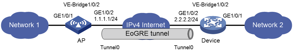
Network configuration
As shown in Figure 6, the AP and Device are connected to Network 1 and Network 2, respectively. Establish an IPv4 EoGRE tunnel between the AP and Device to interconnect Network 1 and Network 2.
Prerequisites
Configure an IP address for each interface, and make sure the AP and Device can reach each other.
Procedure
1. Configure the AP:
# Create a Layer 2 VEB interface.
<AP> system-view
[AP] interface ve-bridge 1/0/2
[AP-VE-Bridge1/0/2] quit
# Create tunnel interface Tunnel 0 and set the tunnel mode to IPv4 EoGRE.
[AP] interface tunnel 0 mode eogre
# Configure the source address of the tunnel as the IP address of GigabitEthernet 1/0/2 on the AP.
[AP-Tunnel0] source 1.1.1.1
# Configure the destination address of the tunnel as the IP address of GigabitEthernet 1/0/2 on Device.
[AP-Tunnel0] destination 2.2.2.2
# Map VEB interface VE-Bridge 1/0/2 to the tunnel interface.
[AP-Tunnel0] map bridge ve-bridge 1/0/2
[AP-Tunnel0] quit
2. Configure Device:
# Create a Layer 2 VEB interface.
<Device> system-view
[Device] interface ve-bridge 1/0/2
[Device-VE-Bridge1/0/2] quit
# Create tunnel interface Tunnel 0 and set the tunnel mode to IPv4 EoGRE.
[Device] interface tunnel 0 mode eogre
# Configure the source address of the tunnel as the IP address of GigabitEthernet 1/0/2 on Device.
[Device-Tunnel0] source 2.2.2.2
# Configure the destination address of the tunnel as the IP address of GigabitEthernet 1/0/2 on the AP.
[Device-Tunnel0] destination 1.1.1.1
# Map VEB interface VE-Bridge 1/0/2 to the tunnel interface.
[Device-Tunnel0] map bridge ve-bridge 1/0/2
[Device-Tunnel0] quit
Verifying the configuration
# Display tunnel interface information on the AP.
[AP] display interface tunnel 0
Tunnel0
Current state: UP
Line protocol state: UP
Description: Tunnel0 Interface
Bandwidth: 64kbps
Maximum transmission unit: 64000
Internet protocol processing: Disabled
Tunnel source 1.1.1.1, destination 2.2.2.2
Tunnel keepalive disabled
Tunnel TTL 255
Tunnel protocol/transport EoGRE/IP
Last clearing of counters: Never
Last 300 seconds input rate: 0 bytes/sec, 0 bits/sec, 0 packets/sec
Last 300 seconds output rate: 0 bytes/sec, 0 bits/sec, 0 packets/sec
Input: 0 packets, 0 bytes, 0 drops
Output: 0 packets, 0 bytes, 0 drops
# Display tunnel interface information on Device.
[Device] display interface tunnel 0
Tunnel0
Current state: UP
Line protocol state: UP
Description: Tunnel0 Interface
Bandwidth: 64kbps
Maximum transmission unit: 64000
Internet protocol processing: Disabled
Tunnel source 2.2.2.2, destination 1.1.1.1
Tunnel keepalive disabled
Tunnel TTL 255
Tunnel protocol/transport EoGRE/IP
Last clearing of counters: Never
Last 300 seconds input rate: 0 bytes/sec, 0 bits/sec, 0 packets/sec
Last 300 seconds output rate: 0 bytes/sec, 0 bits/sec, 0 packets/sec
Input: 0 packets, 0 bytes, 0 drops
Output: 0 packets, 0 bytes, 0 drops
# Verify that Network 1 can ping Network 2 successfully. (Details not shown.)
Troubleshooting EoGRE
The key to configuring EoGRE is to keep the configuration consistent. Most faults can be located by using the debugging gre or debugging tunnel command. This section analyzes one type of fault for illustration, with the scenario shown in Figure 7.

Hosts at both ends of an EoGRE tunnel cannot ping each other
Symptom
The interfaces at both ends of the tunnel are configured correctly and can ping each other, but interfaces on Network 1 and Network 2 cannot ping each other.
Solution
To resolve the issue:
1. Execute the display ip routing-table command on Device A and Device B to view whether Device A has a route over tunnel 0 to Network 2 and whether Device B has a route over tunnel 0 to Network 1.
2. If such a route does not exist, execute the ip route-static command in system view to add the route.
3. If the issue persists, contact H3C Support.