- Table of Contents
-
- 04-Network Connectivity Configuration Guide
- 00-Preface
- 01-About the network connectivity configuration guide
- 02-MAC address table configuration
- 03-Ethernet link aggregation configuration
- 04-Port isolation configuration
- 05-VLAN configuration
- 06-Loop detection configuration
- 07-Spanning tree configuration
- 08-LLDP configuration
- 09-Layer 2 forwarding configuration
- 10-PPP configuration
- 11-ARP configuration
- 12-IP addressing configuration
- 13-DHCP configuration
- 14-DHCPv6 configuration
- 15-DNS configuration
- 16-NAT configuration
- 17-EoGRE configuration
- 18-IP performance optimization configuration
- 19-IPv6 basics configuration
- 20-Basic IP routing configuration
- 21-Static routing configuration
- 22-IPv6 static routing configuration
- 23-Multicast overview
- 24-IGMP snooping configuration
- 25-MLD snooping configuration
- Related Documents
-
| Title | Size | Download |
|---|---|---|
| 10-PPP configuration | 275.19 KB |
Interaction process for PPPoE user onboarding
PPPoE MTU and MRU negotiation method
PPPoE client tasks at a glance
Configuring a dialer interface
Display and maintenance commands for PPPoE
Display and maintenance commands for PPPoE server
Display and maintenance commands for PPPoE client
Example: Configuring a PPPoE client in permanent mode
Example: Configuring a PPPoE client in on-demand mode
Example: Configuring a PPPoE client in diagnostic mode
Configuring PPPoE
About PPPoE
Point-to-Point Protocol over Ethernet (PPPoE) extends PPP by transporting PPP frames encapsulated in Ethernet over point-to-point links.
PPPoE specifies the methods for establishing PPPoE sessions and encapsulating PPP frames over Ethernet. PPPoE requires a point-to-point relationship between peers instead of a point-to-multipoint relationship as in multi-access environments such as Ethernet. PPPoE provides Internet access for the hosts in an Ethernet through a remote access device and implement access control, authentication, and accounting on a per-host basis. Integrating the low cost of Ethernet and scalability and management functions of PPP, PPPoE gained popularity in various application environments, such as residential access networks.
For more information about PPPoE, see RFC 2516.
PPPoE network structure
PPPoE uses the client/server model. The PPPoE client initiates a connection request to the PPPoE server. After session negotiation between them is complete, a session is established between them, and the PPPoE server provides access control, authentication, and accounting to the PPPoE client.
PPPoE network structures are classified into router-initiated and host-initiated network structures depending on the starting point of the PPPoE session.
Router-initiated network structure
As shown in Figure 1, in the router-initiated network structure, a PPPoE session is established between two devices, and all user endpoints transmit data through this PPPoE session. In this network structure, the PPPoE client is located in the intranet, and the PPPoE server is provided by the carrier. A user endpoint does not require the installation of PPPoE client dialup software. Typically, an enterprise uses a shared account to access the network.
Figure 1 Router-initiated network structure
Host-initiated network structure
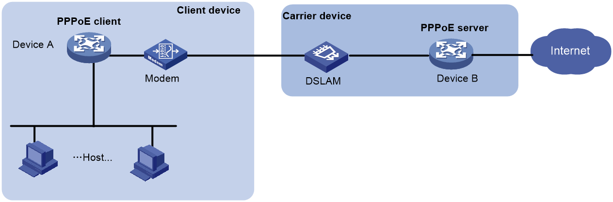
As shown in Figure 2, each user endpoint must have PPPoE client dialup software installed in the host-initiated network structure. These endpoints act as PPPoE clients, and establish individual PPPoE sessions with the PPPoE server of the carrier. This approach benefits carriers by enabling effective accounting and management control of users.
Figure 2 Host-initiated network structure

PPPoE packet structure
The format of PPPoE packets carries PPP packets in Ethernet frames. The encapsulation structure of the packets is as shown in Figure 3.
Figure 3 PPPoE packet structure
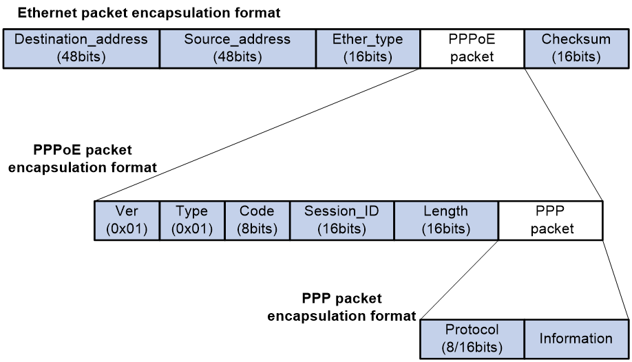
Table 1 Fields in the PPPoE packets
|
Field |
Description |
|
Destination address |
An Ethernet unicast destination address or Ethernet broadcast address (0xffffffffffff): · In the discovery phase, the field value is a unicast or broadcast address. The PPPoE client uses a broadcast address to find the PPPoE server, and then uses a unicast address after determining the PPPoE server. · In the session phase, this field must be the unicast address of the peer end determined during the discovery phase. |
|
Source_address |
Ethernet MAC address of the source device. |
|
Ether_type |
Set to 0x8863 (discovery phase) or 0x8864 (session phase). |
|
Ver |
4 bits long. This field represents the PPPoE version number. The value is 0x1. |
|
Type |
4 bits long. This field represents the PPPoE type. The value is 0x1. |
|
Code |
8 bits. This field represents the PPPoE packet type. Possible values include: · 0x00—Session data. · 0x09—PADI packet. · 0x07—PADO or PADT packet. · 0x19—PADR packet. · 0x65—PADS packet. |
|
Session_ID |
16 bits long. The value is fixed for a given PPP session and, in fact, defines a PPP session along with the Ethernet Source_address and Destination_address fields. The value of 0xffff is reserved for future use and must not be used. |
|
Length |
16 bits long. This field defines the length of the PPPoE payload. It does not include the length of the Ethernet or PPPoE headers. |
|
PPP packet |
For the PPP packet structure, see the frame format for PPP packet encapsulation in basic PPP concepts. |
Interaction process for PPPoE user onboarding
The PPPoE user onboarding process involves two phases: PPPoE negotiation and PPP negotiation. PPP negotiation includes LCP negotiation, PAP/CHAP authentication, NCP negotiation, and other phases.
PPPoE negotiation
In the PPPoE negotiation phase, the device assigns a session ID for the user's PPPoE access. A session ID uniquely identifies a virtual PPPoE link between the user and the device. The negotiation process of PPPoE is as shown in Figure 4.
1. The user broadcasts a PPPoE Active Discovery Initiation (PADI) packet, which contains the type of service the user wants.
2. Upon receiving this PADI packet, all access concentrators on the Ethernet (such as the device in the diagram) compare the requested service with their own capabilities. The device that can provide the service responds with a PPPoE Active Discovery Offer (PADO) packet.
3. The user might receive PADO packets from different devices. The user selects a device from the returned PADO packets based on certain conditions and sends to the device a non-broadcast session request packet, PPPoE Active Discovery Request (PADR). The PADR packet has the required service information encapsulated.
4. The selected device starts to enter the PPP session phase after receiving the PADR packet. The device will generate a session ID to uniquely identify the PPPoE session between the device and the host. The device includes this specific session ID in a session confirmation packet, PPPoE Active Discovery Session-confirmation (PADS), and sends the PADS packet to the user. If no errors occur, the device enters the PPP session phase. When the user receives the PADS packet, the user also enters the PPP session phase if no errors occur.
Figure 4 PPPoE negotiation process

PPP negotiation
PPP negotiation includes LCP negotiation, PAP/CHAP authentication, NCP negotiation, and other phases.
LCP negotiation
After the PPP negotiation phase starts, the LCP negotiation process starts first. The LCP negotiation process is as shown in Figure 5.
1. The user and the device send an LCP Configure-Request packet to each other.
2. After receiving the Configure-Request packet from the peer end, the local end responds appropriately based on the negotiation option support in the packet. For more information, see Table 2. If both ends have responded with a Configure-Ack packet, the LCP link has been successfully established. If not, both ends will continue to send requests.
¡ If the peer end responds with a Configure-Ack packet within the configured LCP negotiation interval and negotiation times, the LCP link has been successfully established.
¡ If the peer end has not responded with a Configure-Ack packet after the set LCP negotiation times, LCP negotiation will be terminated.
3. After the LCP link is successfully established, the device will periodically send LCP Echo-Requests to the user and then receive the Echo-Replies from the peer to detect whether the LCP link is normal and maintain the LCP connection.
Figure 5 Basic LCP negotiation process

Table 2 Response packet type list
|
Response packet type |
Description |
|
Configure-Ack |
If the end fully supports the LCP options of the peer end, the end responds with a Configure-Ack packet that fully carries the options in the request of the peer end. |
|
Configure-Nak |
If the end supports the negotiation options of the peer end but does not accept the negotiated content, the end responds with a Configure-Nak packet filled with the expected content. For example, if the MRU value of the peer is 1500 and the local end expects the MRU value of 1492, the local end will fill in 1492 in the Configure-Nak packet. |
|
Configure-Reject |
If the end does not support the negotiation options of the peer end, the end responds with a Configure-Reject packet carrying the unsupported options. |
Authentication phase
After the LCP negotiation is completed, the PPP link enters the authentication phase. Two authentication methods are supported: PAP authentication and CHAP authentication.
· PAP authentication
PAP is a two-way handshake protocol that authenticates a user by using a username and password. PAP transmits the username and password in plain text. Therefore, PAP is suitable for environments with relatively low network security requirements. The PAP authentication process is as shown in Figure 6.
a. The authenticatee sends the username and password to the authenticator.
b. The authenticator checks for this user in the user table at this end.
¡ If the user exists, the authenticator identifies whether the authentication password is correct.
- If the password is correct, the authenticator sends an Authenticate-ACK packet to the peer end to notify the peer end that it is allowed to enter the next phase of negotiation.
- If the password is not correct, the authenticator sends an Authenticate-NAK packet to the peer to notify the peer of authentication failure.
¡ If the user does not exist, the authentication will fail.
|
|
NOTE: After authentication failure, the link will not be directly closed. The link will be closed only when the number of authentication failures reaches a certain value. |
Figure 6 PAP authentication process

· CHAP authentication
CHAP is a three-way handshake protocol. CHAP transmits only the username rather than the user password over the network, so it is more secure than PAP. The authentication process of CHAP is as shown in Figure 7.
a. The authenticator initiates the authentication request, and sends a packet (Challenge) with a random number to the authenticatee and also sends the username to the authenticatee.
b. Upon receiving the authentication request from the authenticator, the authenticatee first identifies whether a CHAP password is configured on the local interface.
- If a CHAP password is configured, the authenticatee uses the hash algorithm to calculate a hash value based on the packet ID, configured password, and random number in the packet. Then, the authenticatee sends this hash value and the authenticatee's username (Response) back to the authenticator.
- If no CHAP password is configured, the authenticatee looks up the password corresponding to the username in the user table at this end based on the authenticator username in this packet. The authenticatee uses the hash algorithm to calculate a hash value based on the packet ID, the user's password, and the random number in the packet. The authenticatee sends the obtained hash value and the authenticatee's username back to the authenticator. (Response).
c. The authenticator uses the hash algorithm to calculate a hash value based on the packet ID, its saved password for the authenticatee, and the random number in the Challenge packet. The authenticator then compares the calculated hash value with the hash value in the Response packet. If the comparison result is consistent, authentication succeeds. If the comparison result is inconsistent, authentication fails.
Figure 7 CHAP authentication process

NCP negotiation
The main function of NCP negotiation is to negotiate network layer parameters of PPP packets, such as IPCP and IPv6CP, among which IPCP is the most common protocol. PPPoE users mainly obtain their IP addresses or IP address ranges for accessing the network through the IPCP protocol.
As shown in Figure 8, the NCP process is similar to the LCP process. When users and devices exchange Configure-Request packets and respond with Configure-Ack packets, NCP negotiation succeeds and users can normally access the network.
Figure 8 Basic NCP negotiation process

The following section will describe the commonly used IPCP and IPv6CP protocols in NCP negotiation.
· IPCP
The IPCP negotiation process is performed based on the PPP state machine. After both parties negotiate and they exchange configuration information through Configure-Request, Configure-Ack, and Configure-Nak packets, the IPCP state changes from initial (or closed) state to opened state finally. The condition for the IPCP state to become opened is that both the sender and receiver have sent and received Ack packets.
During the IPCP negotiation process, the negotiation packet can contain multiple options (parameters), such as IP address, gateway, and mask. The rejection or denial of each option does not affect the successful negotiation of IPCP, and IPCP also supports negotiation without options.
· IPv6CP
IPv6 Control Protocol (IPv6CP) is a network control protocol. IPv6CP is mainly responsible for configuring settings on both ends of a point-to-point link, enabling and disabling the IPv6 protocol module, and negotiating parameters such as interface ID and IPv6 compression protocol. IPv6CP uses the same packet exchange mechanism as the Link Control Protocol (LCP). However, the IPv6CP packets can be exchanged only when PPP reaches the network layer protocol phase. IPv6CP packets received before this phase will be dropped.
In the current software version, the IPv6CP negotiation options only support interface IDs and do not support the IPv6 compression protocols.
In an IPv6 network, PPP users and IPoE users both need to use the ND protocol or DHCPv6 protocol to allocate global unicast addresses and configuration information. The IA_PD option of the DHCPv6 protocol is used to allocate IPv6 prefixes to LAN interfaces in routed mode on CPEs.
PPPoE MTU and MRU negotiation method
During the interaction process of PPPoE user onboarding, the values of interface MTU and MRU will be negotiated, and then both sides will send and receive packets. The main negotiation methods include the following types.
The PPPoE connection is enabled to negotiate the MRU according to relevant standards
PPPoE discovery phase:
· If the user packet carries the PPP-Max-Payload field and the value is greater than 1492, the value will be compared with the MTU value on the BAS interface minus 8. The smaller value will be used as the negotiated value and named PPP_MRU_Max. This negotiated value is not the final MTU negotiation result, but one of the reference values.
· If the PPP-Max-Payload field carried in the user packet is less than or equal to 1492, PPP_MRU_Max takes the default value of 1492 as one of the reference values.
· If the user packet does not carry the PPP-Max-Payload field, then PPP_MRU_Max is set to 0 and not used as one of the reference values.
LCP negotiation phase:
· If the user carries the MRU field in the Config-Request packet during the LCP phase, the following rules apply:
¡ If the MRU carried in the user packet is equal to the PPP_MRU_Max negotiated in the PPPoE discovery phase, the MRU carried in the user packet will be used as the final MTU for the user.
¡ If the MRU carried in the user packet is not equal to the PPP_MRU_Max negotiated in the PPPoE discovery phase or the PPP_MRU_Max is 0, the MRU carried in the user packet will be compared with the MTU value on the VT interface minus 8. The smaller value will be used as the final MTU for the user.
· If the user's Config-Request packet during the LCP phase does not carry the MRU field, 1492 will be compared with the MTU value on the VT interface minus 8. The smaller value will be used as the final MTU for the user.
The PPPoE connection is disabled from negotiating the MRU according to relevant standards
PPPoE discovery phase:
· If the user packet carries the PPP-Max-Payload field, the smaller value between this value and the MTU on the BAS interface is used as the negotiated value and named PPP_MRU_Max. This value is not the final MTU negotiation result, but one of the reference values.
· If the user packet does not carry the PPP-Max-Payload field, the value for PPP_MRU_Max is the default value 0 and is not used as a reference value.
LCP negotiation phase:
· If the user includes the MRU field in the Config-Request packet during the LCP phase, the value will be compared with the MTU on the VT interface. The smaller value will be taken as the final MTU for the user.
· If the user does not include the MRU field in the Config-Request packet during the LCP phase, the following rules apply:
¡ If the user does not negotiate PPP_MRU_Max during the PPPoE discovery phase, the MTU on the VT interface will be used as the final MTU for the user.
¡ If PPP_MRU_Max is negotiated in the PPPoE discovery phase, the smaller value of the MTU on the VT interface and PPP-Max-Payload is used as the final MTU for the user.
Configuring a PPPoE client
Operation mode
A PPPoE session can operate in one of the following modes:
· Permanent mode—A PPPoE session is established immediately when the line is physically up. This type of session remains until the physical link comes down or until the session is disconnected.
· On-demand mode—A PPPoE session is established when there is a demand for data transmission instead of when the line is physically up. It is terminated when idled for a specific period of time.
· Diagnostic mode—A PPPoE session is established immediately after the device configurations finish. The device automatically terminates the PPPoE session and then tries to re-establish a PPPoE session at a pre-configured interval. By establishing and terminating PPPoE sessions periodically, you can monitor the operating status of the PPPoE link.
The PPPoE session operating mode is determined by your configuration on the dialer interface:
· Permanent mode—Used when you set the link idle time to 0 by using the dialer timer idle command and do not configure the dialer diagnose command.
· On-demand mode—Used when you set the link idle time to a non-zero value by using the dialer timer idle command and do not configure the dialer diagnose command.
· Diagnostic mode—Used when you configure the dialer diagnose command.
PPPoE client tasks at a glance
To configure a PPPoE client, perform the following tasks:
1. Configuring a dialer interface
2. Configuring a PPPoE session
3. (Optional.) Resetting a PPPoE session
Configuring a dialer interface
About this task
Before establishing a PPPoE session, you must first create a dialer interface and configure bundle DDR on the interface. Each PPPoE session uniquely corresponds to a dialer bundle, and each dialer bundle uniquely corresponds to a dialer interface. A PPPoE session uniquely corresponds to a dialer interface.
Procedure
1. Enter system view.
system-view
2. Create a dialer group and configure a dial rule.
dialer-group group-number rule { ip | ipv6 } { deny | permit | acl { acl-number | name acl-name } }
Configure this command only when the PPPoE session operates in on-demand mode.
3. Create a dialer interface and enter its view.
interface dialer number
4. Assign an IP address to the interface.
ip address { address mask | ppp-negotiate }
By default, no IP address is configured.
5. Enable bundle DDR on the interface.
dialer bundle enable
By default, bundle DDR is disabled.
6. Associate the interface with the dial rule by associating the interface with the corresponding dialer group.
dialer-group group-number
By default, a dialer interface is not assigned to any dialer group.
Configure this command only when the PPPoE session operates in on-demand mode.
7. Configure the link-idle timeout timer.
dialer timer idle idle [ in | in-out ]
The default setting is 120 seconds.
When this timer is set to 0 seconds, the PPPoE session operates in permanent mode. Otherwise, the PPPoE session operates in on-demand mode.
8. Configure the DDR application to operate in diagnostic mode.
dialer diagnose [ interval interval ]
By default, the DDR application operates in non-diagnostic mode.
Execute this command only when the PPPoE session operates in diagnostic mode.
9. (Optional.) Set the auto-dial interval.
dialer timer autodial autodial-interval
The default setting is 300 seconds.
DDR starts the auto-dial timer after the link is disconnected and originates a new call when the auto-dial timer expires.
As a best practice, set a shorter auto-dial interval for DDR to soon originate a new call.
10. (Optional.) Set the MTU for the dialer interface
mtu size
By default, the MTU on a dialer interface is 1500 bytes.
The dialer interface fragments a packet that exceeds the configured MTU, and adds a 2-byte PPP header and a 6-byte PPPoE header to each fragment. You should modify the MTU of a dialer interface to make sure the total length of any fragment packet is less than the MTU of the physical interface.
11. (Optional.) Set the TCP MSS for the dialer interface.
tcp mss value
By default, the TCP MSS is not set for an interface.
Typically, the TCP MSS is the IP MTU of the outgoing interface minus 40. For the dialer interface of a PPPoE client application, you must modify its TCP MSS to 1452. Then, the total length of a packet will not exceed the MTU of the interface of the corresponding PPPoE session after a 2-byte PPP header, 6-byte PPPoE header, and 40-byte IP header are added to the packet.
For more information this command, see IP performance optimization commands in Network Connectivity Command Reference.
Configuring a PPPoE session
About this task
After a PPPoE session is successfully established, the system automatically creates a VA interface for exchanging packets with the peer. To display information about VA interfaces, execute the display interface virtual-access command. VA interfaces cannot be manually configured.
After the PPPoE session is terminated, the corresponding VA interface is automatically deleted.
Procedure
1. Enter system view.
system-view
2. Enter interface view.
interface interface-type interface-number
3. Create a PPPoE session and specify a dialer bundle for the session.
pppoe-client dial-bundle-number number [ no-hostuniq ]
The number argument in this command must take the same value as the configured dialer interface number.
Resetting a PPPoE session
About this task
After you reset a PPPoE session in permanent mode, the device establishes a new PPPoE session when the autodial timer expires.
After you reset a PPPoE session in on-demand mode, the device establishes a new PPPoE session when there is a demand for data transmission.
Procedure
To reset a PPPoE session, execute the following command in user view:
reset pppoe-client { all | dial-bundle-number number }
Display and maintenance commands for PPPoE
Display and maintenance commands for PPPoE server
Execute display commands in any view and reset commands in user view.
|
Task |
Command |
|
Display PPPoE server negotiation packet statistics. |
display pppoe-server packet statistics |
|
Display packet statistics for PPPoE sessions. |
display pppoe-server session packet [ interface interface-type interface-number ] |
|
Display summary information for PPPoE sessions. |
display pppoe-server session summary [ interface interface-type interface-number ] |
|
Display information about blocked users. |
display pppoe-server throttled-mac [ interface interface-type interface-number ] |
|
Display VA pool information. |
display pppoe-server va-pool |
|
Clear PPPoE sessions. |
reset pppoe-server { all | interface interface-type interface-number | virtual-template number } |
|
Clear PPPoE server negotiation packet statistics. |
reset pppoe-server packet statistics |
Display and maintenance commands for PPPoE client
Execute display commands in any view and reset commands in user view.
|
Task |
Command |
|
Display summary information for a PPPoE session. |
display pppoe-client session summary [ dial-bundle-number number ] |
|
Display the protocol packet statistics for a PPPoE session. |
display pppoe-client session packet [ dial-bundle-number number ] |
|
Clear the protocol packet statistics for a PPPoE session. |
reset pppoe-client session packet [ dial-bundle-number number ] |
PPPoE configuration examples
Example: Configuring a PPPoE client in permanent mode
Network configuration
As shown in Figure 9, Router serves as a PPPoE server. Configure AP as a PPPoE client operating in permanent mode.

Procedure
1. Configure Router as the PPPoE server:
# Configure an IP address for Virtual-Template 1 and specify an IP address for the peer.
<Router> system-view
[Router] interface virtual-template 1
[Router-Virtual-Template1] ip address 1.1.1.1 255.0.0.0
[Router-Virtual-Template1] remote address 1.1.1.2
# Configure Virtual-Template 1 to authenticate the peer by using PAP.
[Router-Virtual-Template1] ppp authentication-mode pap domain dm1
[Router-Virtual-Template1] quit
# Enable the PPPoE server on Ten-GigabitEthernet 1/0/1, and bind the interface to Virtual-Template 1.
[Router] interface ten-gigabitethernet 1/0/1
[Router-Ten-GigabitEthernet1/0/1] pppoe-server bind virtual-template 1
[Router-Ten-GigabitEthernet1/0/1] quit
# Configure a PPPoE user.
[Router] local-user user1 class network
[Router-luser-network-user1] password simple 123456TESTplat&!
[Router-luser-network-user1] service-type ppp
[Router-luser-network-user1] quit
# Configure local AAA for the PPP users in ISP domain dm1.
[Router] domain dm1
[Router-isp-dm1] authentication ppp local
[Router-isp-dm1] accounting ppp local
[Router-isp-dm1] authorization ppp local
[Router-isp-dm1] quit
2. Configure AP as the PPPoE client:
# Create dialer group 1 and configure a dial rule for it.
<AP> system-view
[AP] dialer-group 1 rule ip permit
# Enable bundle DDR on Dialer 1.
[AP] interface dialer 1
[AP-Dialer1] dialer bundle enable
# Associate Dialer 1 with dialer group 1.
[AP-Dialer1] dialer-group 1
# Configure Dialer 1 to obtain an IP address through PPP negotiation.
[AP-Dialer1] ip address ppp-negotiate
# On Dialer 1, configure the PAP username and password sent from AP to Router as user1 and 123456TESTplat&! when AP is authenticated by Router by using PAP.
[AP-Dialer1] ppp pap local-user user1 password simple 123456TESTplat&!
[AP-Dialer1] quit
# Configure a PPPoE session that corresponds to dialer bundle 1 (dialer bundle 1 corresponds to Dialer 1).
[AP] interface vlan-interface 1
[AP-Vlan-interface1] pppoe-client dial-bundle-number 1
[AP-Vlan-interface1] quit
# Configure the PPPoE session to operate in permanent mode.
[AP] interface dialer 1
[AP-Dialer1] dialer timer idle 0
# Set the DDR auto-dial interval to 60 seconds.
[AP-Dialer1] dialer timer autodial 60
[AP-Dialer1] quit
# Configure a static route.
[AP] ip route-static 1.1.1.1 255.0.0.0 dialer 1
Verifying the configuration
# Display summary information about the PPPoE session established between AP and Router (PPPoE server).
[AP-Dialer1] display pppoe-client session summary
Bundle ID Interface VA RemoteMAC LocalMAC State
1 1 Vlan1 VA0 00e0-1400-4300 00e0-1500-4100 SESSION
Example: Configuring a PPPoE client in on-demand mode
Network configuration
As shown in Figure 10, Router serves as a PPPoE server. Configure AP as a PPPoE client operating in on-demand mode, and set the link idle-timeout timer to 150 seconds.

Procedure
1. Configure Router as the PPPoE server:
# Configure an IP address for Virtual-Template 1 and specify an IP address for the peer.
<Router> system-view
[Router] interface virtual-template 1
[Router-Virtual-Template1] ip address 1.1.1.1 255.0.0.0
[Router-Virtual-Template1] remote address 1.1.1.2
# Configure Virtual-Template 1 to authenticate the peer by using PAP.
[Router-Virtual-Template1] ppp authentication-mode pap domain dm1
[Router-Virtual-Template1] quit
# Enable the PPPoE server on Ten-GigabitEthernet 1/0/1, and bind the interface to Virtual-Template 1.
[Router] interface ten-gigabitethernet 1/0/1
[Router-Ten-GigabitEthernet1/0/1] pppoe-server bind virtual-template 1
[Router-Ten-GigabitEthernet1/0/1] quit
# Configure a PPPoE user.
[Router] local-user user1 class network
[Router-luser-network-user1] password simple 123456TESTplat&!
[Router-luser-network-user1] service-type ppp
[Router-luser-network-user1] quit
# Configure local AAA for the PPP users in ISP domain dm1.
[Router] domain dm1
[Router-isp-dm1] authentication ppp local
[Router-isp-dm1] accounting ppp local
[Router-isp-dm1] authorization ppp local
[Router-isp-dm1] quit
2. Configure AP as the PPPoE client.
# Create dialer group 1 and configure a dial rule for it.
<AP> system-view
[AP] dialer-group 1 rule ip permit
# Enable bundle DDR on Dialer 1.
[AP] interface dialer 1
[AP-Dialer1] dialer bundle enable
# Associate Dialer 1 with dialer group 1.
[AP-Dialer1] dialer-group 1
# Configure Dialer 1 to obtain an IP address through PPP negotiation.
[AP-Dialer1] ip address ppp-negotiate
# On Dialer 1, configure the PAP username and password sent from AP to Router as user1 and 123456TESTplat&! when AP is authenticated by Router by using PAP.
[AP-Dialer1] ppp pap local-user user1 password simple 123456TESTplat&!
[AP-Dialer1] quit
# Configure a PPPoE session that corresponds to dialer bundle 1 (dialer bundle 1 corresponds to Dialer 1).
[AP] interface vlan-interface 1
[AP-Vlan-interface1] pppoe-client dial-bundle-number 1
[AP-Vlan-interface1] quit
# Configure a static route.
[AP] ip route-static 1.1.1.1 255.0.0.0 dialer 1
# Set the link-idle timeout timer to 150 seconds.
[AP] interface dialer 1
[AP-Dialer1] dialer timer idle 150
[AP-Dialer1] quit
Verifying the configuration
# Display summary information about the PPPoE session established between AP and Router (PPPoE server).
[AP-Dialer1] display pppoe-client session summary
Bundle ID Interface VA RemoteMAC LocalMAC State
1 1 Vlan1 VA0 00e0-1400-4300 00e0-1500-4100 SESSION
Example: Configuring a PPPoE client in diagnostic mode
Network configuration
As shown in Figure 11, Router serves as a PPPoE server. Configure AP as a PPPoE client operating in diagnostic mode, and set the diagnostic interval to 200 seconds.

Procedure
1. Configure Router as the PPPoE server:
# Configure an IP address for Virtual-Template 1 and specify an IP address for the peer.
<Router> system-view
[Router] interface virtual-template 1
[Router-Virtual-Template1] ip address 1.1.1.1 255.0.0.0
[Router-Virtual-Template1] remote address 1.1.1.2
# Configure Virtual-Template 1 to authenticate the peer by using PAP.
[Router-Virtual-Template1] ppp authentication-mode pap domain dm1
[Router-Virtual-Template1] quit
# Enable the PPPoE server on Ten-GigabitEthernet 1/0/1, and bind the interface to Virtual-Template 1.
[Router] interface gigabitethernet 1/0/
[Router-Ten-GigabitEthernet1/0/1] pppoe-server bind virtual-template 1
[Router-Ten-GigabitEthernet1/0/1] quit
# Configure a PPPoE user.
[Router] local-user user1 class network
[Router-luser-network-user1] password simple 123456TESTplat&!
[Router-luser-network-user1] service-type ppp
[Router-luser-network-user1] quit
# Configure local AAA for the PPP users in ISP domain dm1.
[Router] domain dm1
[Router-isp-dm1] authentication ppp local
[Router-isp-dm1] accounting ppp local
[Router-isp-dm1] authorization ppp local
[Router-isp-dm1] quit
2. Configure AP as the PPPoE client.
# Create dialer group 1 and configure a dial rule for it.
<AP> system-view
[AP] dialer-group 1 rule ip permit
# Enable bundle DDR on Dialer 1.
[AP] interface dialer 1
[AP-Dialer1] dialer bundle enable
# Associate Dialer 1 with dialer group 1.
[AP-Dialer1] dialer-group 1
# Configure Dialer 1 to obtain an IP address through PPP negotiation.
[AP-Dialer1] ip address ppp-negotiate
# On Dialer 1, configure the PAP username and password sent from AP to Router as user1 and 123456TESTplat&! when AP is authenticated by Router by using PAP.
[AP-Dialer1] ppp pap local-user user1 password simple 123456TESTplat&!
[AP-Dialer1] quit
# Configure a PPPoE session that corresponds to dialer bundle 1 (dialer bundle 1 corresponds to Dialer 1).
[AP] interface vlan-interface 1
[AP-Vlan-interface1] pppoe-client dial-bundle-number 1
[AP-Vlan-interface1] quit
# Configure the PPPoE session to operate in diagnostic mode, and set the diagnostic interval to 200 seconds.
[AP] interface dialer 1
[AP-Dialer1] dialer diagnose interval 200
# Set the DDR auto-dial interval to 10 seconds.
[AP-Dialer1] dialer timer autodial 10
Verifying the configuration
# Display summary information about the PPPoE session established between AP and Router (PPPoE server).
[AP-Dialer1] display pppoe-client session summary
Bundle ID Interface VA RemoteMAC LocalMAC State
1 1 Vlan1 VA0 00e0-1400-4300 00e0-1500-4100 SESSION