- Table of Contents
-
- H3C Servers UniSystem Configuration Examples-6W102
- 01-UniSystem Bulk HDM&BIOS Import Configuration Examples
- 02-H3C UniSystem Cloning Installation Configuration Examples
- 03-UniSystem SMTP Configuration Examples
- 04-H3C UniSystem Cluster Creation Configuration Examples
- 05-H3C UniSystem SNMP Configuration Examples
- 06-H3C UniSystem RAID Configuration Examples
- 07-H3C UniSystem Rack Server Deployment Configuration Examples
- 08-UniSystem Bulk Component Update Configuration Examples
- 09-H3C UniSystem Server Inspection Configuration Example
- 10-H3C Unisystem REPO Acquisition and Use Configuration Examples
- 11-H3C UniSystem LDAP Management Configuration Example
- 12-H3C UniSystem Secure Erase Configuration Examples
- 13-H3C UniSystem Intelligent Version Management Configuration Examples
- 14-H3C UniSystem Bulk IP Settings Configuration Examples
- Related Documents
-
| Title | Size | Download |
|---|---|---|
| 07-H3C UniSystem Rack Server Deployment Configuration Examples | 973.29 KB |
H3C UniSystem
Rack Server Deployment Configuration Examples
Copyright © 2025 New H3C Technologies Co., Ltd. All rights reserved.
No part of this manual may be reproduced or transmitted in any form or by any means without prior written consent of New H3C Technologies Co., Ltd.
Except for the trademarks of New H3C Technologies Co., Ltd., any trademarks that may be mentioned in this document are the property of their respective owners.
The information in this document is subject to change without notice.
Introduction
|
|
NOTE: Starting from version 2.59, FIST software has been renamed as UniSystem. |
The following information describes the auto bulk deployment of rack servers through UniSystem. UniSystem enables automatic delivery of server templates to rack servers through a switch port. This can realize automatic deployment of servers, configuration of RAID, HDM, and BIOS, and installation of OS.
Prerequisites
Procedures and information in the examples might be slightly different depending on the software or hardware version of the products.
The configuration was created and verified in a lab environment, and all the servers and software were started with the factory default configuration. When you are working on a live network, make sure you understand the potential impact of every command on your network.
The following information is provided based on the assumption that you have basic knowledge of the UniSystem server template.
Configuration example
Network requirement
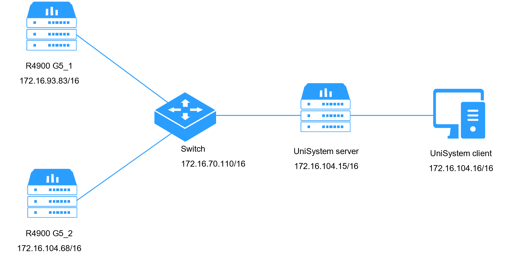
As shown in Figure 1, deploy UniSystem on a PC as the UniSystem server, and use another PC as the UniSystem client. Connect the Ethernet ports of the two PCs and two R4900 G5 servers to a switch on the same LAN, and configure IP addresses so that the UniSystem client, UniSystem server, and server devices can communicate normally. The server template should be applied automatically when two R4900 G5 servers are incorporated by UniSystem. For the detailed networking information, see Table 1.
Figure 1 UniSystem network diagram
|
Devices roles |
Device information |
Remarks |
|
UniSystem server |
UniSystem IP address |
172.16.104.15/16 |
|
Default UniSystem administrator account |
admin |
|
|
Default UniSystem administrator password |
Password@_ |
|
|
UniSystem client |
OS IP address |
172.16.104.16/16 |
|
Switch |
Switch model |
H3C S6800-54QT |
|
Switch management IP address |
172.16.70.110 |
|
|
Switch administrator account |
admin |
|
|
Switch administrator password |
123456 |
|
|
R4900 G5 server_1 |
Server model |
H3C UniServer R4900 G5 |
|
HDM IP address |
172.16.93.83/16 |
|
|
Storage controller model |
RAID-LSI-9361-8i(2G)-1-X |
|
|
R4900 G5 server_2 |
Server model |
H3C UniServer R4900 G5 |
|
HDM IP address |
172.16.104.68/16 |
|
|
Storage controller model |
RAID-LSI-9361-8i(2G)-1-X |
Analysis
1. Create a server template.
2. Bind the server template to the switch port connected to the HDM port of the server.
3. Add the servers in the off state to UniSystem and verify that the server template is applied automatically.
Software versions used
This configuration example was created and verified on UniSystem-2.40.
Restrictions and guidelines
· When you configure the server template, the server model, HDM version, BIOS version, and hardware configuration must match the actual environment of the target server to which the template is applied. Otherwise, the server template cannot be applied successfully.
· Make sure that the HDM management port of the server is connected to the switch port bound with the server template.
Procedures
Logging in to UniSystem
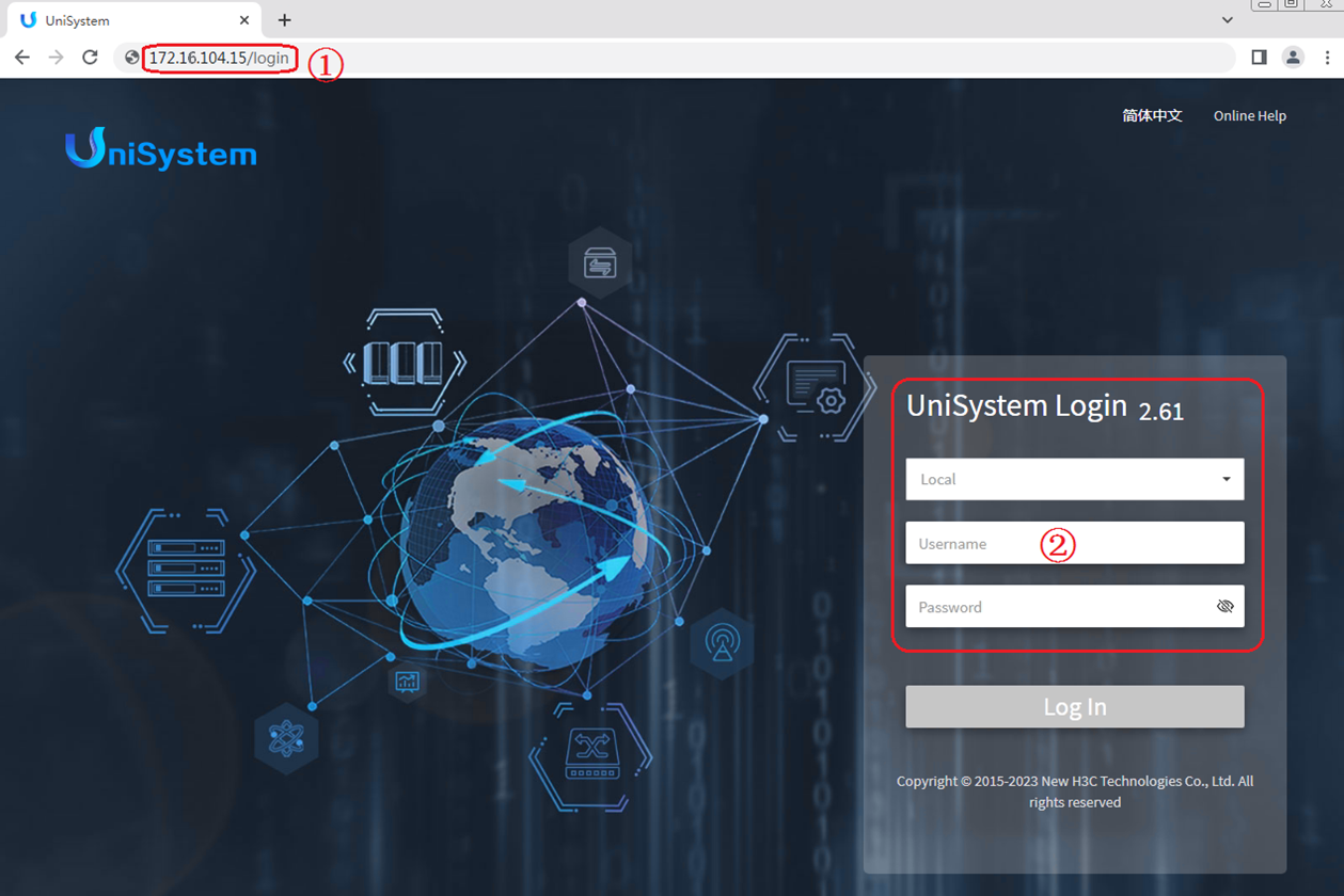
1. As shown in Figure 2 (1), open the browser on UniSystem client, and enter the UniSystem server address (https://172.16.104.15).
2. As shown in Figure 2 (2), enter the default username admin and password Password@_ on the login interface.
3. Click Log In.
Uploading an OS image
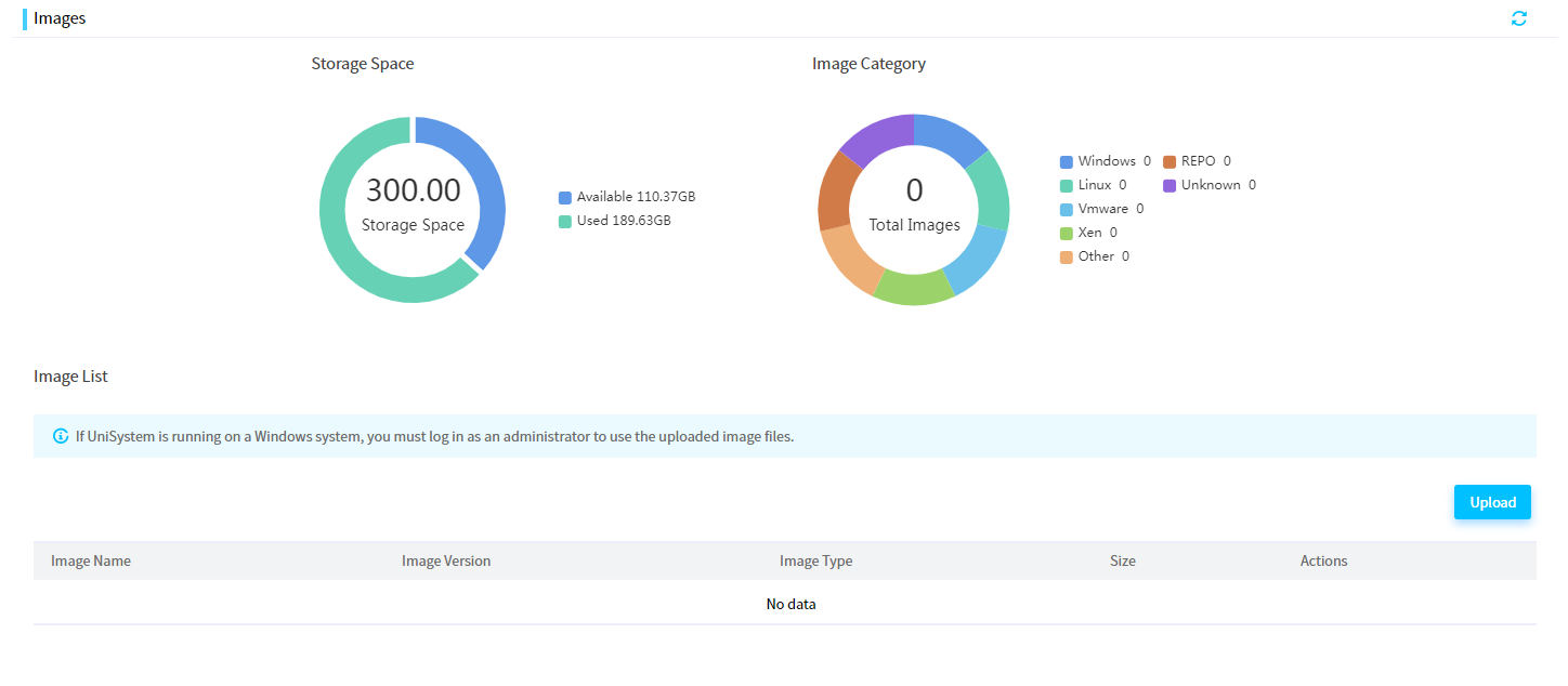
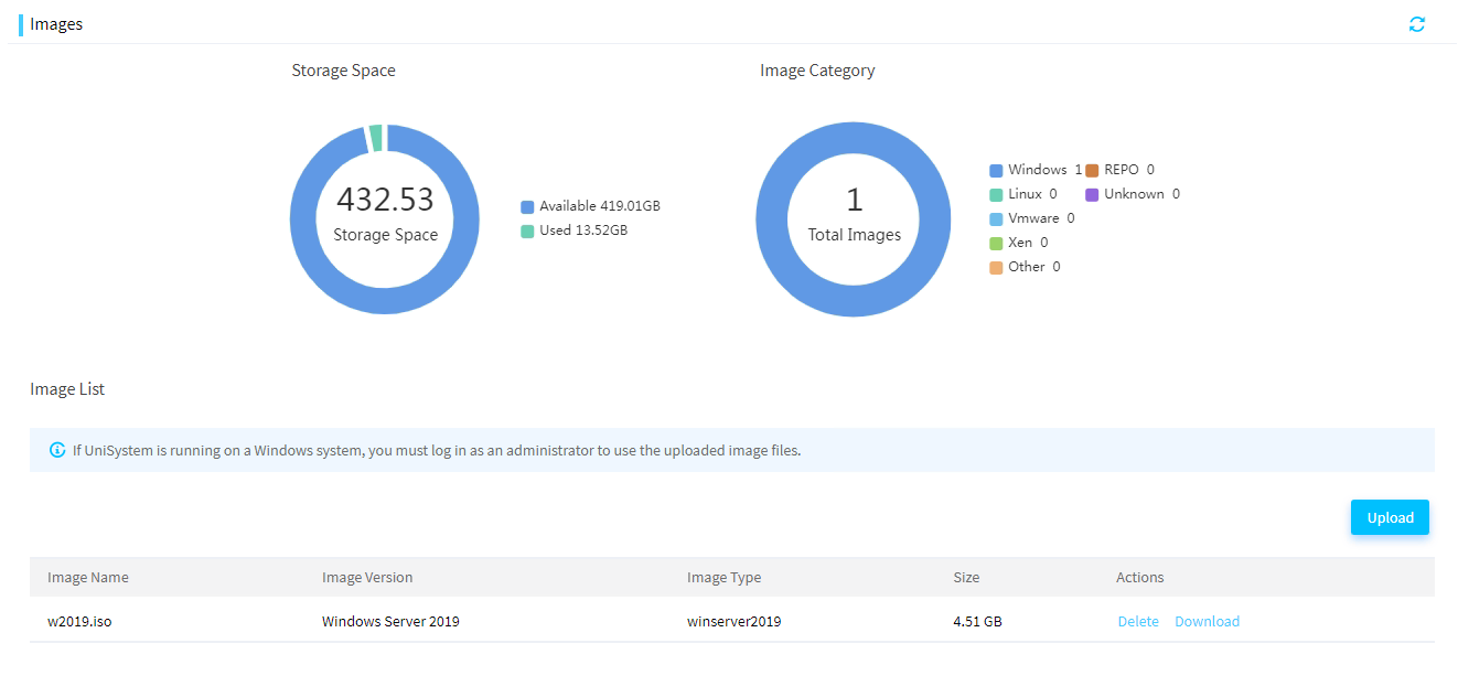
1. Click Menu > Templates > Images, as shown in Figure 2. Click Upload.
Figure 3 Images
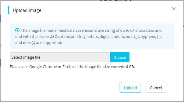
2. As shown in Figure 4, in the dialog box that opens, click Browse to select the OS image file.
3. Click Upload to upload the OS image file to the UniSystem server.
4. After the image is uploaded, you can view it on the Images page, as shown in Figure 5.
Creating a server template
1. Click Menu > Templates > Server Templates to navigate to the page.
2. Click Add.
3. As shown in Figure 6, in the Basic Info column, enter the server template name and server template description (optional), and select the server model in the drop-down box.
4. As shown in Figure 6, in the HDM Settings column and BIOS Settings column, click Select Template to select the exported HDM/BIOS template.
Figure 6 Adding a server template

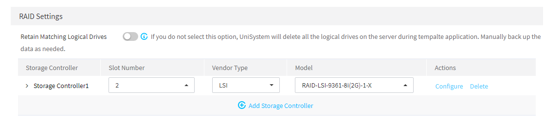
5. As shown in Figure 7, in the RAID Settings column, click Add Storage Controller. Select Slot Number, Vendor Type, and Model of the storage controller and then click Configure to configure the logical drive.
Figure 7 Storage controller settings
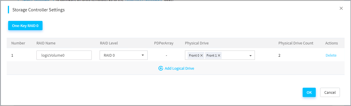
6. As shown in Figure 8, in the dialog box that opens, click Add Logical Drive, and configure RAID Name, RAID Level, and Physical Drive. Then click OK to complete RAID configuration.
Figure 8 Logical drive settings
7. As shown in Figure 9, in the OS Settings column, select Windows for the operating system, Windows Server 2019 for the operating system type, and select the uploaded OS image file from the image file list.
Figure 9 Configuring system settings
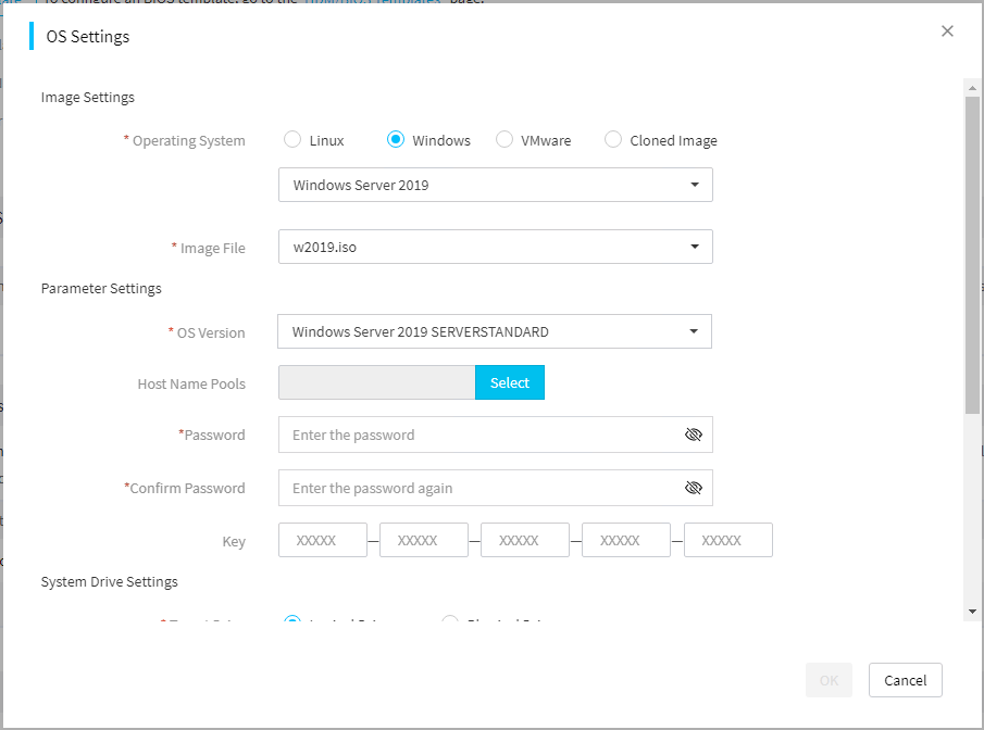
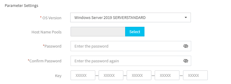
8. Configure the system parameters, as shown in Figure 10.
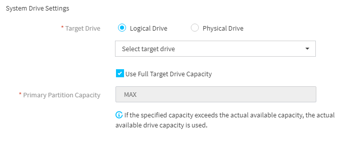
9. As shown in Figure 11, configure the target drive and specify the location where the OS is to be installed. Select Logical Drive for the target drive and select the configured logical drive in RAID Settings in the drop-down box.
Figure 11 System drive settings
10. Click OK and the template of the R4900 G5 server is created.
Binding a switch port
1. Click Menu > Devices > Switch List and select Add Switch.
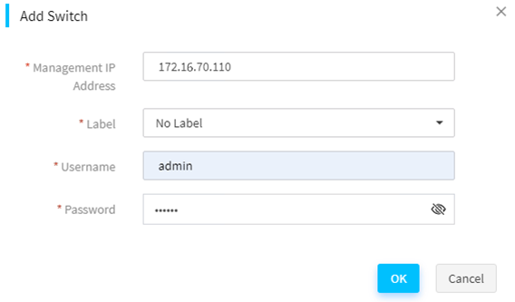
2. As shown in Figure 12, in the dialog box that opens, enter the switch IP address, administrator account, and password and then click OK to add the switch to UniSystem.
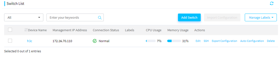
3. After the switch is added, you can view it on the switch list page, as shown in Figure 13.
4. Click Auto-Configuration for the switch.
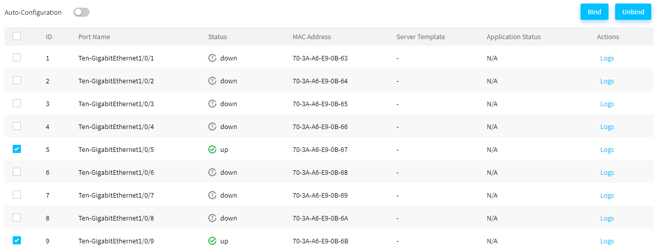
5. As shown in Figure 14, select the HDM management port of the server connected to the switch, and click Bind.
Figure 14 Auto-Configuration page
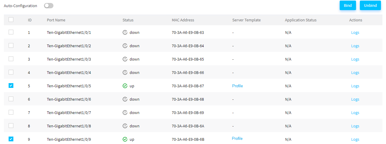
6. In the dialog box that opens, select a server template and then click OK to complete binding, as shown in Figure 15.
Figure 15 Binding to a server template

7. Enable Auto-Configuration, as shown in Figure 16.
Adding the server
1. Click Menu > Devices > Server List.
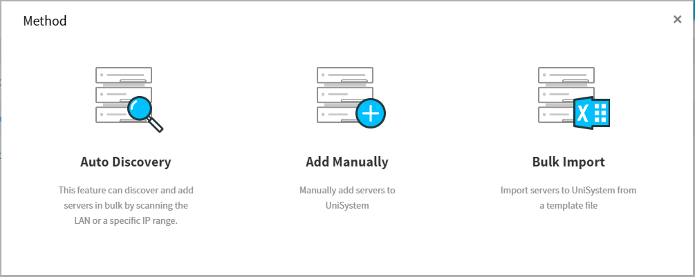
2. Click Add the Server. As shown in Figure 17, in the dialog box that opens, select the method of adding the server. Select Bulk Import this time.
Figure 17 Selecting the method of adding the server
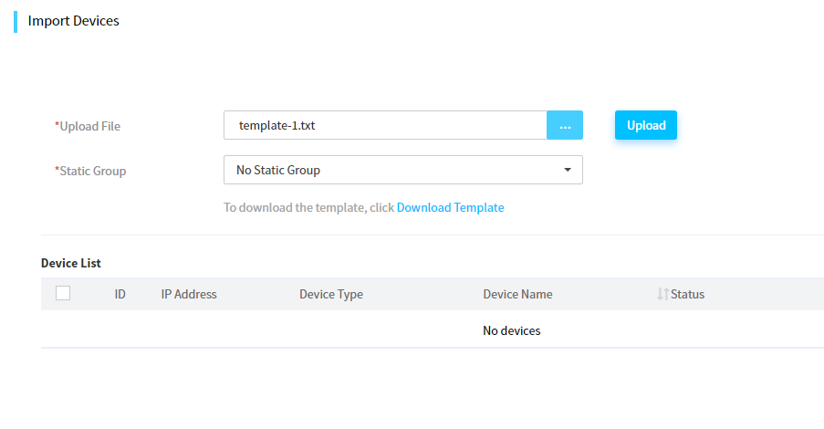
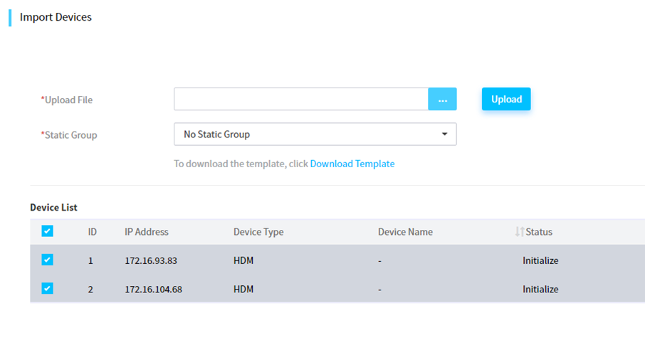
3. Navigate to the server importing page, as shown in Figure 18.

4. Click Download Template to download a template package. Decompress the package and fill in the information of the two R4900 G5 servers to be added based on the examples and rules listed in the template, as shown in Figure 19.

5. As shown in Figure 20, click ... to select a device list file. Then click Upload to upload the file containing the information of two R4900 G5 servers.
6. As shown in Figure 21, in the device list, select the servers that you want to add, and click OK. Before adding the servers, make sure that the servers are powered off. Otherwise, the server template deployment may be affected.
Applying a server template automatically
1. Click Menu > Devices > Server List.
2. As shown in Figure 22, after the servers are successfully added, check the operation statuses of the servers and verify that the server template is automatically applied.
Figure 22 Applying a server template
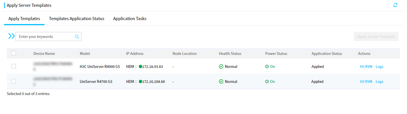
3. Click Menu > Deployment > Apply Server Templates to navigate to the server template application status page. Check the status and progress of applying the current server template.
4. Wait until the sever template is applied. The Application Status column displays Succeeded, indicating that the server template is applied.
Verifying the configuration
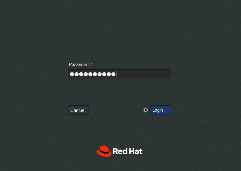
1. Click Menu > Devices > Server List. As shown in Figure 22, click H5 KVM in the Actions column for a server to check the OS installation status.
2. After the server starts and the OS login page shown in Figure 23 opens, use the password in the server template to log in to the operating system. If you can log in to the system, it indicates that the server template has been successfully applied.
Related documentation
· H3C Servers UniSystem User Guide
· H3C Servers UniSystem Installation Guide
