- Table of Contents
-
- H3C Servers UniSystem Configuration Examples-6W102
- 01-UniSystem Bulk HDM&BIOS Import Configuration Examples
- 02-H3C UniSystem Cloning Installation Configuration Examples
- 03-UniSystem SMTP Configuration Examples
- 04-H3C UniSystem Cluster Creation Configuration Examples
- 05-H3C UniSystem SNMP Configuration Examples
- 06-H3C UniSystem RAID Configuration Examples
- 07-H3C UniSystem Rack Server Deployment Configuration Examples
- 08-UniSystem Bulk Component Update Configuration Examples
- 09-H3C UniSystem Server Inspection Configuration Example
- 10-H3C Unisystem REPO Acquisition and Use Configuration Examples
- 11-H3C UniSystem LDAP Management Configuration Example
- 12-H3C UniSystem Secure Erase Configuration Examples
- 13-H3C UniSystem Intelligent Version Management Configuration Examples
- 14-H3C UniSystem Bulk IP Settings Configuration Examples
- Related Documents
-
| Title | Size | Download |
|---|---|---|
| 04-H3C UniSystem Cluster Creation Configuration Examples | 661.69 KB |
Cluster Creation Configuration Examples
Copyright © 2025 New H3C Technologies Co., Ltd. All rights reserved.
No part of this manual may be reproduced or transmitted in any form or by any means without prior written consent of New H3C Technologies Co., Ltd.
Except for the trademarks of New H3C Technologies Co., Ltd., any trademarks that may be mentioned in this document are the property of their respective owners.
The information in this document is subject to change without notice.
Introduction
|
|
NOTE: Starting from version 2.59, FIST software has been renamed as UniSystem. |
The following information describes the typical configuration of the cluster creation feature of UniSystem.
When UniSystem is deployed in an AE module, the 1+1 primary/backup cluster can be created. When the primary node becomes faulty, UniSystem automatically switches services to the backup node so that users' services can continue uninterrupted without data loss. Users can replace the faulty backup nodes to maintain high availability of the cluster.
Prerequisites
Procedures and information in the examples might be slightly different depending on the software or hardware version of the products.
The configuration was created and verified in a lab environment, and all the servers and software were started with the factory default configuration. When you are working on a live network, make sure you understand the potential impact of every command on your network.
The following information is provided based on the assumption that you have basic knowledge of the UniSystem cluster management feature.
Restrictions and cautions
The cluster management feature is only available when the UniSystem server is running on the AE module, and UniSystem only allows creation of clusters for two AE modules.
Configuration example
Network requirement
As shown in Figure 1, the two AE modules are located in B16000 chassis A and B respectively. The hard drive and memory configurations of the two AE modules are identical. Use the AE module where the UniSystem software runs as the UniSystem server and use one PC as the UniSystem client. Connect the Ethernet port of the PC, OM modules (management ports) and ICM modules (service ports) of chassis A and B to the switches respectively, and configure IP addresses so that the UniSystem client, UniSystem server, and chassis A and B can communicate normally. Create a cluster for two AE modules, with one as primary and the other as backup. In this scenario, when the primary node fails, the backup node takes over as the new primary node. This ensures that the service continues uninterrupted. For the detailed networking information, see Table 1.
Figure 1 UniSystem cluster creation network diagram
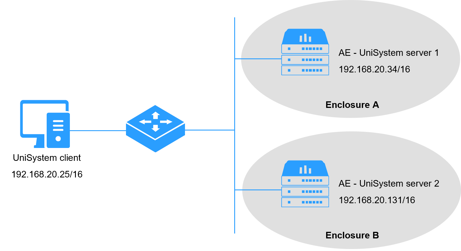
Table 1 UniSystem cluster creation network information
|
Devices roles |
Device information |
Remarks |
|
UniSystem client |
OS IP address |
192.168.20.25/16 |
|
Chassis A |
OM IP address |
172.17.0.239/16 |
|
AE module 1 (primary UniSystem server) |
Management port (vmng.om) IP address |
192.168.20.34/16 |
|
Service port (enp5s0f1) IP address |
172.16.20.34/16 |
|
|
UniSystem username (default) |
admin |
|
|
UniSystem password (default) |
Password@_ |
|
|
Chassis B |
OM IP address |
172.17.0.139/16 |
|
AE module 2 (backup UniSystem server) |
Management port (vmng.om) IP address |
192.168.20.131/16 |
|
Service port (enp5s0f1) IP address |
172.16.20.131/16 |
|
|
UniSystem username (default) |
admin |
|
|
UniSystem password (default) |
Password@_ |
Analysis
1. To create a cluster and to ensure that the primary node and the backup node in the cluster can communicate with each other normally, perform the following configurations for the two AE modules.
¡ Set the host name. The host name of the primary node is different from that of the backup node and no duplicate host names exist in the network.
¡ Set the IP addresses of the service ports (enp5s0f1) and the management ports (vmng.om) for the primary UniSystem and backup UniSystem to be in the same network segment, so that the management network and the service network of the primary node and the backup node are interconnected.
¡ Set the primary UniSystem and the backup UniSystem so that they use the same Network Time Protocol (NTP) server. This ensures that the time difference between the UniSystem systems on the primary node and on the backup node is within the controllable range (10s).
2. Log in to UniSystem on the primary node and complete the cluster creation.
Software versions used
This configuration example was created and verified on UniSystem-2.40.
Restrictions and guidelines
· When you set the network and the host name, follow these restrictions and guidelines:
¡ The host name cannot be set to localhost or contain numbers only.
¡ Make sure that the UniSystem host name is unique on the primary and backup nodes.
¡ As a best practice, set the IP addresses of the ports for communication between the primary and backup nodes in the cluster to the static IP addresses.
¡ The ports for communication between the primary and backup nodes should have the same subnet mask.
¡ Do not configure multiple IP addresses of the same network segment for each port. Otherwise, the cluster creation attempt may fail.
· Do not modify the host name, system time, and network configuration of UniSystem during and after cluster creation.
· After the cluster is created, you cannot return to the standalone mode.
Procedures
Configuring the primary node
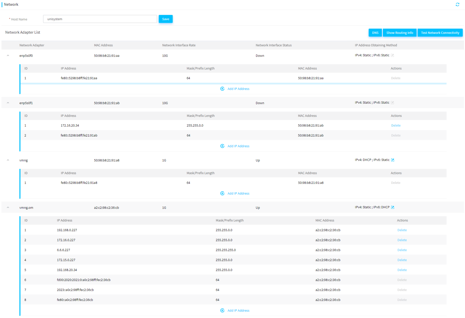
1. Log in to UniSystem on the primary node. Click Menu > System Management > Network Settings, as shown in Figure 2.
2. Set the host name to fist-master.
3. Set the IP address of the service port enp5s0f1 on the primary node to 172.16.20.34/16 and the IP address of the management port vmng.om on the primary node to 192.168.20.34/16.
Figure 2 Setting the primary node network
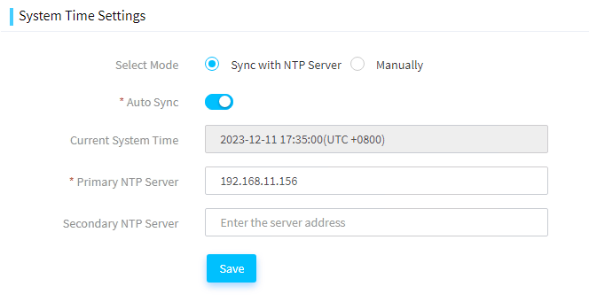
4. Click Menu > System Management > Time Setting.
5. As shown in Figure 3, select Sync with NTP Server and enter an available IP address of the NTP server in the network.
|
|
NOTE: You can also select Manually to set the time so that the time difference between the primary and backup nodes is within 10s. Here an NTP server is configured as an example. |
Figure 3 Setting the time on the primary node

Configuring the backup node
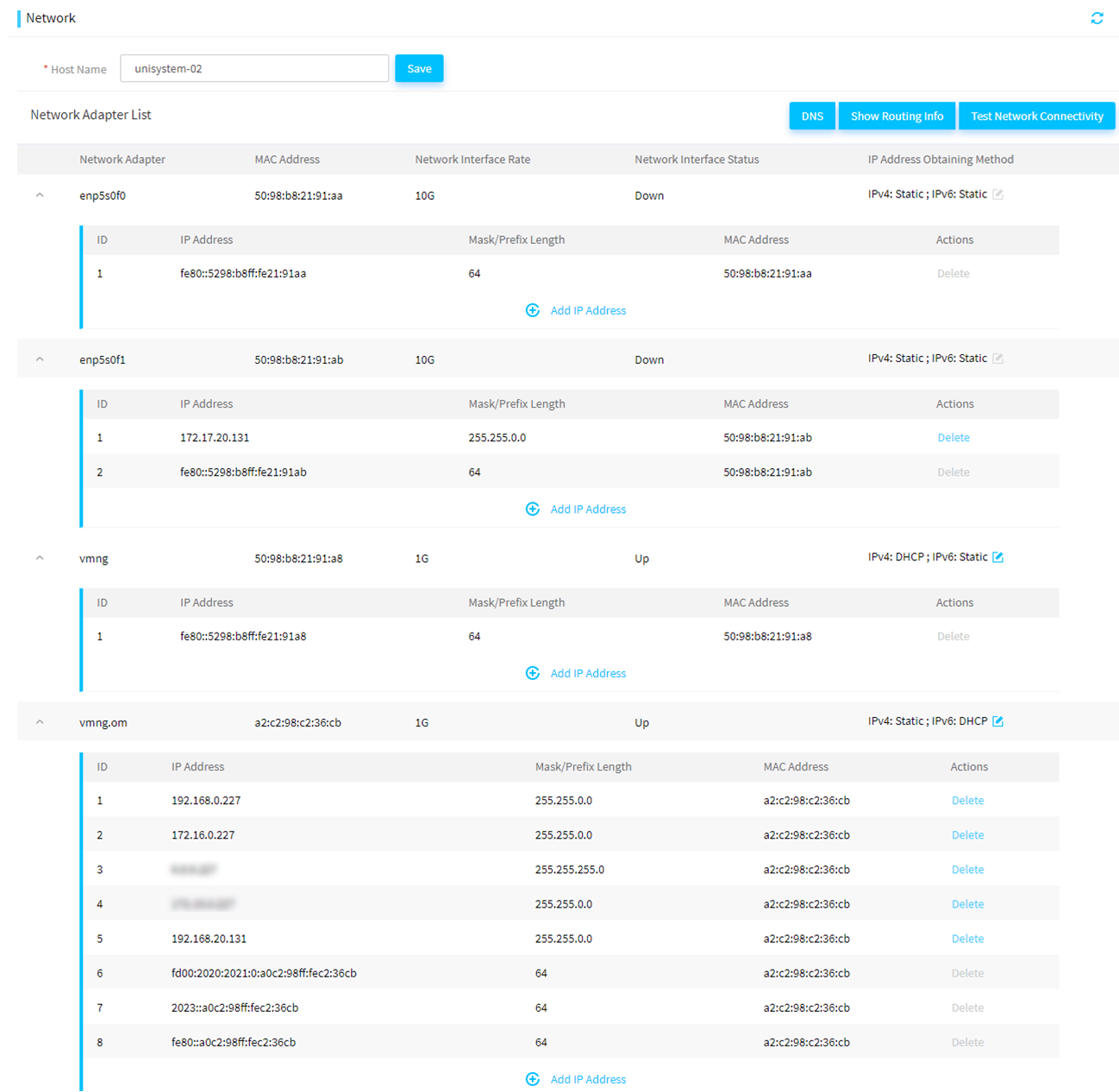
1. Log in to UniSystem on the backup node. Click Menu > System Management > Network Settings, as shown in Figure 4.
2. Set the host name to unisystem-02.
3. Set the IP address of the service port enp5s0f1 on the backup node to 172.16.20.131/16 and the IP address of the management port vmng.om on the backup node to 192.168.20.131/16. Note that the subnet mask of the IP address of the backup node must be the same as that of the IP address of the primary node.
Figure 4 Setting the backup node network
4. Click Menu > System Management > Time Setting.
5. As shown in Figure 5, select Sync with NTP Server and enter the same IP address of the NTP server as the primary node.
Figure 5 Setting the time on the backup node
Creating a cluster
1. Click Menu > System Management > Cluster Management to navigate to the cluster management page.
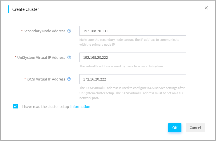
2. Click Create Cluster. As shown in Figure 6, in the dialog box that opens, enter the required parameters and then click OK.
¡ Set Secondary Node Address to 192.168.20.131, that is, the IP address of the port vmng.om of the AE module as the backup node.
¡ Set UniSystem Virtual IP Address to 192.168.20.222. As a best practice, configure the IP address to be in the same network segment with the IP address of the management port vmng.om. This IP address is used for accessing the UniSystem cluster later.
¡ Set iSCSI Virtual IP Address to 172.16.20.222. As a best practice, configure the IP address to be in the same network segment with the IP address of the service port enp5s0f1. This IP address is used for the drive-free start feature of the UniSystem cluster.
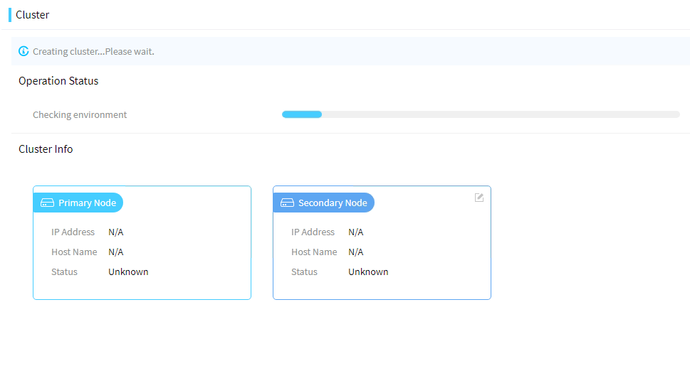
3. Figure 7 shows that a cluster is being created. Please be patient as it can take a long time to synchronize data.
|
|
CAUTION: · Do not disconnect the power supply or the network connection during cluster creation. · Do not perform any other operations on UniSystem on the primary node. |
4. After the cluster is created, an operation prompt pops up. UniSystem will restart automatically.
Figure 8 Completing cluster creation
Verifying configuration
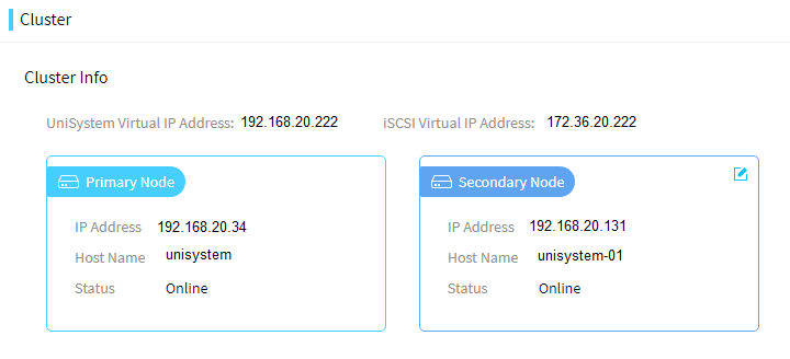
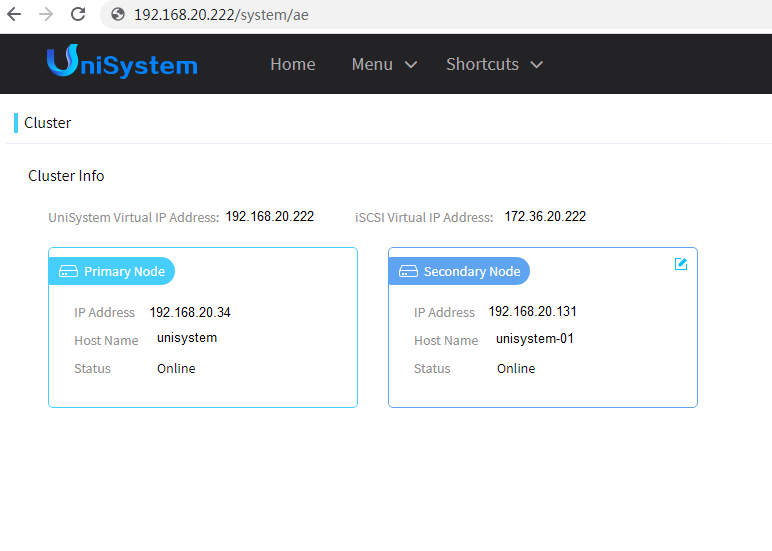
1. Use the virtual IP address of UniSystem 192.168.20.222 to log in to UniSystem. Click Menu > System Management > Cluster Management to view cluster information.
2. Power off the primary node and stop the UniSystem server on the primary node. You can also use the virtual IP address of UniSystem to log in to UniSystem. If you check cluster information, you will find that the previous backup node automatically switches to the primary node, as shown in Figure 9. It indicates that the switchover is successful.
Figure 9 Switchover successful
Related documentation
H3C Servers UniSystem User Guid
