- Table of Contents
-
- H3C SecPath M9000-X Multiservice Security Gateway Series Installation Guide-6W100
- 00-Preface
- 01-Chapter 1 Chassis views
- 02-Chapter 2 Preparing for Installation
- 03-Chapter 3 Installing the Gateway
- 04-Chapter 4 Accessing the Gateway and Configuring Basic Settings
- 05-Chapter 5 Troubleshooting
- 06-Chapter 6 Replacing Removable Components
- 07-Appendix A FRUs and Compatibility Matrixes
- 08-Appendix B Technical Specifications
- 09-Appendix C LEDs
- 10-Appendix D Cables
- 11-Appendix E Slot arrangement and interface numbering
- 12-Appendix F Engineering labels
- 13-Appendix G Cabling Recommendations
- 14-Appendix H Repackaging the Gateway
- Related Documents
-
| Title | Size | Download |
|---|---|---|
| 09-Appendix C LEDs | 824.47 KB |
Appendix C LEDs
The M9000-X gateway series provides a lot of LEDs. You can determine the gateway operating status by examining the LEDs.
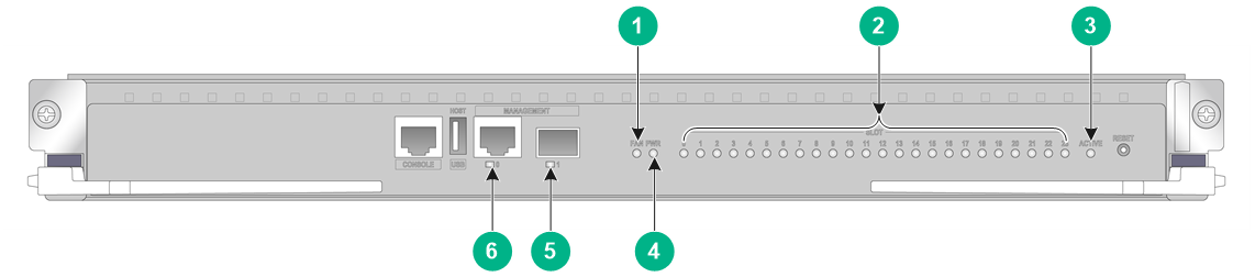
Supervisor engine module (SEM) LEDs
|
(1) Fan tray status LED (FAN) |
(2) Card status LEDs |
|
(3) SEM active/standby status LED |
(4) Power status LED (PWR) |
|
(5) Fiber management Ethernet port LED |
(6) Copper management Ethernet port LED |
Figure 2 NSQM7SUPB0 SEM LEDs
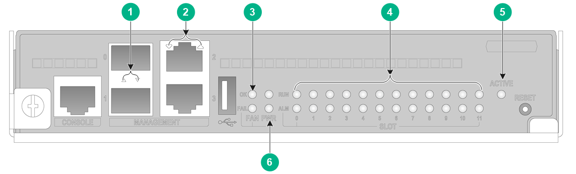
|
(1) Fiber management Ethernet port LEDs |
(2) Coper management Ethernet port LEDs |
|
(3) Fan tray status LEDs |
(4) Card status LEDs |
|
(5) SEM active/standby status LED |
(6) Power status LEDs |
Figure 3 NSQM7SUPA0-CN SEM LEDs
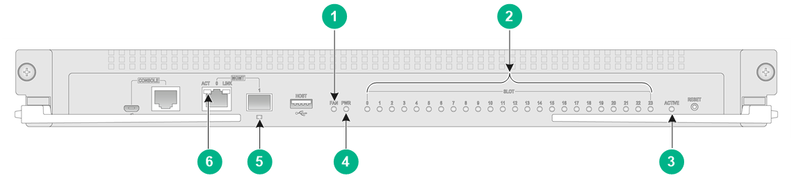
|
(1) Fan tray status LED (FAN) |
(2) Card status LEDs |
|
(3) SEM active/standby status LED |
(4) Power status LED (PWR) |
|
(5) Fiber management Ethernet port LED |
(6) Coper management Ethernet port LED |
Figure 4 NSQM7SUPB0-CN SEM LEDs
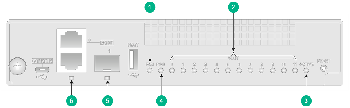
|
(1) Fan tray status LED (FAN) |
(2) Card status LEDs |
|
(3) SEM active/standby status LED |
(4) Power status LED (PWR) |
|
(5) Fiber management Ethernet port LED |
(6) Coper management Ethernet port LED |
Fiber/copper management Ethernet port LEDs
Each SEM has management Ethernet fiber/copper port LEDs to indicate the link status and data forwarding status of the management Ethernet port.
Table 1 Description for the fiber/copper management Ethernet port LED on the NSQM7SUPA0/NSQM7SUPB0 SEM
|
LINK |
Description |
|
Flashing |
A link is present on the port, and the port is receiving or sending data. |
|
Steady on |
A link is present. |
|
Off |
No link is present. |
Table 2 Description for the copper management Ethernet port LED on the NSQM7SUPA0-CN/NSQM7SUPB0-CN SEM
|
LINK |
ACT |
Description |
|
Steady on |
Flashing |
A link is present on the port, and the port is receiving or sending data. |
|
Steady on |
Off |
A link is present. |
|
Off |
Off |
No link is present. |
Table 3 Description for the fiber management Ethernet port LED on the NSQM7SUPA0-CN/NSQM7SUPB0-CN SEM
|
LINK |
Description |
|
Flashing |
A link is present on the port, and the port is receiving or sending data. |
|
Steady on |
A link is present. |
|
Off |
No link is present. |
Power status LED
Each SEM provides power status LEDs to indicate the operating status of power supplies.
Table 4 Description for the power status LED on the NSQM7SUPB0 SEM
|
OK |
FAIL |
Description |
|
On |
Off |
The power supplies are operating correctly. |
|
Off |
On |
One or multiple power supplies are faulty. |
|
Off |
Off |
The gateway is not powered on. |
Table 5 Description for the power status LED on the NSQM7SUPA0/NSQM7SUPA0-CN/NSQM7SUPB0-CN
|
Status |
Description |
|
Steady green |
The power supplies are operating correctly. |
|
Steady red |
One or multiple power supplies are faulty. |
|
Off |
The gateway is not powered on. |
Fan tray status LEDs
Each SEM provides fan tray status LEDs to indicate the operating status of fan trays.
Table 6 Description for the fan tray status LEDs on NSQM7SUPB0
|
OK |
FAIL |
Description |
|
Steady on |
Off |
All fan trays are operating correctly. |
|
Off |
Steady on |
A fan tray has failed, or no fan tray is present. |
|
Off |
Off |
The gateway is not powered on. |
Table 7 Description for the fan tray status LED on the NSQM7SUPA0/NSQM7SUPA0-CN/NSQM7SUPB0-CN
|
Status |
Description |
|
Steady green |
All fan trays are operating correctly. |
|
Steady red |
A fan tray has failed or no fan tray is present. |
|
Off |
The gateway is not powered on. |
SEM active/standby status LED
Each SEM has one ACTIVE LED to indicate the active or standby status of the SEM.
Table 8 SEM ACTIVE LED description
|
LED status |
Description |
|
Steady on |
The SEM is active. |
|
Off |
· The SEM is in standby status. · The SEM has failed. Examine the card LED for an SEM problem. |
Card LEDs
Each SEM has the LEDs numbered the same as card slots to indicate the status of the active SEM, standby SEM, interface switch modules, service modules, and switching fabric modules in the slots. Table 9 and Table 10 show the LED descriptions.
Table 9 Description for the card LEDs on the NSQM7SUPB0
|
RUN |
ALM |
Description |
|
Flashing at 4 Hz |
Steady on |
The card is loading software. If the LEDs keep in this state, the card software version is not compatible with the gateway software version. |
|
Flashing at 0.5 Hz |
Off |
The card is operating correctly. |
|
Flashing at 0.25 Hz |
The card temperature has exceeded the upper warning threshold or dropped below the lower warning threshold. |
|
|
Steady on |
Steady on |
The card is in boot state or has failed. |
|
Off |
Off |
The card is not present. |
Table 10 Description for the card status LEDs on the NSQM7SUPA0/NSQM7SUPA0-CN/NSQM7SUPB0-CN SEM
|
LED status |
Description |
|
Flashing green (0.5 Hz) |
The card is operating correctly. |
|
Flashing green (4 Hz) |
The card is loading software. If the LED remain in this state, the software of the card does not match that of the device. |
|
Steady green |
The card is starting up. |
|
Steady red |
A major alarm or fault is present on the card. |
|
Flashing red (0.25 Hz) |
The card temperature has exceeded the upper warning threshold or dropped below the lower warning threshold. |
|
Off |
The card is not present or is faulty. |
Firewall module LEDs
The NS-FWFFGA0, NS-FWFFGB0, NS-FWFFGC0, NS-FWFFGD0, and NS-FWFAMA1 firewall modules provide multiple LEDs to indicate the firewall module operating status.
Table 11 Description for the LEDs on the NS-FWFFGA0/NS-FWFFGB0/NS-FWFFGC0/NS-FWFFGD0 firewall module
|
LED |
Mark |
Status |
Description |
|
|
Module status LED |
|
Steady green |
The card is operating correctly, or a minor alarm is present. |
|
|
Flashing green (4 Hz) |
HDM is initializing. |
|||
|
Flashing orange (1 Hz) |
A major alarm is present. |
|||
|
Flashing red (1 Hz) |
A critical alarm is present. |
|||
|
System power/standby LED |
|
Steady green |
The system has powered up. |
|
|
Flashing green |
The system is powering up. |
|||
|
Steady orange |
The system is in standby state. |
|||
|
Off |
The system is powered off. |
|||
|
CPU status LED |
RUN |
Fast flashing green |
The CPU is loading software. |
|
|
Slow flashing green |
The CPU is operating correctly. |
|||
|
Steady red |
A fault is present on the CPU. |
|||
|
Off |
The CPU is not running. |
|||
|
Copper management Ethernet port LED |
- |
Steady green |
A 1 Gbps link is present on the port. |
|
|
Flashing green |
The port is sending or receiving data at 1 Gbps. |
|||
|
Steady yellow |
A 10/100 Mbps link is present on the port. |
|||
|
Flashing yellow |
The port is sending or receiving data at 10/100 Mbps. |
|||
|
Off |
The port is not connected. |
|||
|
100GBSAE-R fiber port LED |
- |
Off |
No link is present on the port. |
|
|
Steady green |
A link is present on the port. |
|||
|
Flashing green |
The port is sending or receiving data. |
|||
Table 12 Description for the LEDs on the NS-FWFAMA1 firewall module
|
LED |
Mark |
Status |
Description |
|
CPU status LED |
RUN |
Fast flashing green |
The CPU is loading software. |
|
Slow flashing green |
The CPU is operating correctly. |
||
|
Steady red |
A fault is present on the CPU. |
||
|
Off |
The CPU is not running. |
||
|
Copper management Ethernet port LED |
-- |
Steady green |
A Gigabit link is present on the port. |
|
Flashing green |
The port is sending or receiving data at 1 Gbps. |
||
|
Off |
No link is present on the port. |
||
|
100GBSAE-R fiber port LED |
- |
Off |
No link is present on the port. |
|
Steady green |
A link is present on the port. |
||
|
Flashing green |
The port is sending or receiving data. |
Switching fabric module LEDs
NSQM5FAB08A1 switching fabric module LEDs
The NSQM7FAB06A0 and NSQM7FAB10A0 switching fabric modules and the fan tray that convers the switching fabric modules each provide a status LED to indicate the operation status for the switching fabric modules.
Table 13 Switching fabric module LED description
|
LED |
Mark |
Status |
Description |
|
Status LED |
RUN/ALM |
Steady green |
The switching fabric module is operating correctly. |
|
Steady red |
The switching fabric module is faulty, or is loading software. |
||
|
Off |
The switching fabric module is not present. |
Table 14 Description for the switching fabric module LED on the fan tray
|
RUN LED |
ALM LED |
Description |
|
Flashing (1 Hz) |
Off |
The switching fabric module is operating correctly. |
|
Off |
On |
The switching fabric module is faulty. |
|
Flashing (1 Hz) |
On |
The switching fabric module is loading software or is operating incorrectly, for example, the temperature of the switching fabric module has exceeded the upper or lower limit. |
|
Off |
Off |
The switching fabric module has not started or is not powered on. |
|
On |
On |
The switching fabric module is in boot state. |
Interface module LEDs
The interface modules provide port LEDs to indicate the link status and data receiving/forwarding status of the ports.
10GE fiber port LED
Table 15 10GE fiber port LED description
|
LED status |
Description |
|
Flashing |
The port is receiving or sending data at 10 Gbps. |
|
On |
A 10 Gbps link is present. |
|
Off |
No link is present. |
40GE fiber port LED
Table 16 40GE fiber port LED description
|
LED status |
Description |
|
Flashing |
The port is receiving or sending data at 40 Gbps. |
|
On |
A 40 Gbps link is present. |
|
Off |
No link is present. |
100GE fiber port LEDs
Table 17 100GE fiber port LED description
|
LED status |
Description |
|
Flashing |
The port is receiving or sending data at 100 Gbps. |
|
On |
A link is present. |
|
Off |
No link is present. |
Fan tray status LEDs
The fan trays for the M9000-X gateways provide LEDs to indicate their operating status.
Table 18 M9000-X06 fan tray LED description
|
OK |
FAIL |
Description |
|
On |
Off |
The fan tray is operating correctly. |
|
Off |
On |
The fan tray is faulty. |
|
Off |
Off |
The fan tray is not powered on. |
Table 19 M9000-X10 fan tray LED description
|
OK/FAIL LED status |
Description |
|
Off |
The fan tray is faulty or not powered on. |
|
Steady green |
The fan tray is operating correctly. |
|
Steady red |
The fan tray is faulty. |
Power supply LEDs
The PSR2400-54A, PSR2400-54D, and PSR3000-54A power supplies each have one AC OK LED and one DC OK LED to indicate its operating status. The PSR3000-54AHD power supply has one IN OK LED and one OUT OK LED to indicate its operating status.
Table 20 PSR2400-54A/PSR2400-54D/PSR3000-54A power supply LED description
|
LED |
Status |
Description |
|
AC OK |
Off |
· The power supply does not have power input. · The input voltage is too low, and the power supply is in self protection state. |
|
Green |
The power supply does not have power input. |
|
|
DC OK |
Green |
The power supply is outputting power correctly. |
|
Orange |
The power supply is in an over-temperature condition. |
|
|
Red |
The power supply is experiencing an output problem, including output short-circuit, output overcurrent, output overvoltage, input under-voltage, or remote power off, and has entered self protection state. |
Table 21 PSR3000-54AHD power supply LED description
|
LED |
Status |
Description |
|
IN OK |
Off |
· The power supply does not have power input. · The input voltage is too low, and the power supply is in self protection state. |
|
Green |
The power supply does not have power input. |
|
|
OUT OK |
Green |
The power supply is outputting power correctly. |
|
Orange |
The power supply is in an over-temperature condition. |
|
|
Red |
The power supply is experiencing an output problem, including output short-circuit, output overcurrent, output overvoltage, input under-voltage, or remote power off, and has entered self protection state. |
